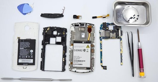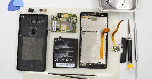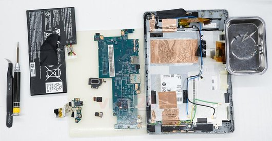
Recommended tools
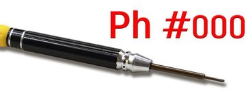
Screwdriver Phillips #000
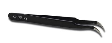
Tweezers
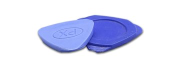
Non-metallic tool
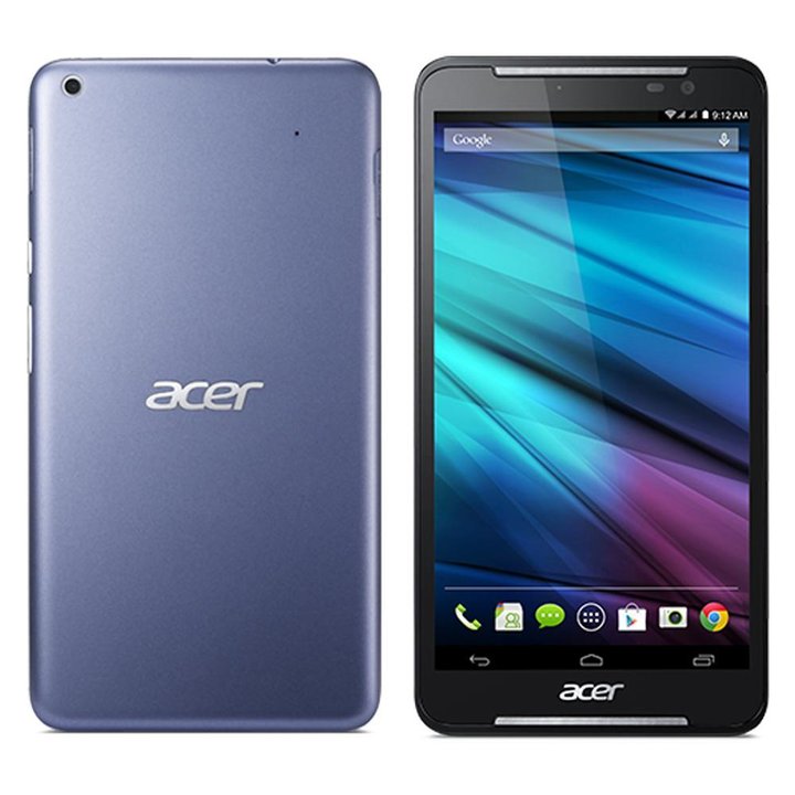
Disassembly/Repair of the mobile device Acer Iconia Talk S A1-734 with each step description and the required set of tools.
6137
Views
4
Likes
—
Share
7
Questions

Step 1.
Remove the tray
Use the ejection tool (aka Needle) or Paperclip. Push the tip all the way into the hole until the tray ejects, and then pull the tray of SIM and Memory card (Micro SD) out.
⚠️ Pay attention! The tool must be inserted into a hole on the edge of the phone's housing. Do not press too hard. It may break the tray eject mechanism.
Step 2.
Open the back cover
Using a spudger or a plastic pick, carefully, around the edge, detach the back cover clips, and remove it.
Do not insert the tool deeply or bend it. Otherwise, the housing may be tampered with or damaged.
Step 3.
Unscrew the screws
Using a screwdriver (Phillips 1.5 mm), unscrew the two screws securing the sub-board.
Step 4.
Remove the sub-board
Disconnect the coaxial cable connector, cable to the mainboard, and loudspeaker connector.
Pry over the edge and remove the loudspeaker.
Remove the sub-board. It may be glued to the frame or attached with attachments like latches or hooks, so be careful.
ℹ️ The sub-board contains a microphone, spring contacts for antenna units.
⚠️ It is not necessary to insert the tool underneath when removing the sub-board. Internal components could be damaged.
Step 5.
Unscrew the screws
Using a screwdriver (cross-head 1.5 mm), unscrew the six screws securing the motherboard.
Step 6.
Remove the cameras
Disconnect connectors on the motherboard and remove the rear and front (selfie) cameras.
Step 7.
Disconnect the connectors
Disconnect the battery connector as soon as possible. It is better to use a non-metal or plastic tool to avoid any damage.
ℹ️ The Acer Iconia Talk S A1-734 model has a battery CS-ACS724SL with 3300 mAh capacity (aka rechargeable battery).
⚠️ It is highly recommended to disconnect the connector to avoid possible short circuits during disassembly.
Pry up the connector of the side buttons cable, display module cable, inter-board cable, and coaxial cable.
⚠️ Be careful when removing the cables from the connectors, the cables are pretty thin, and it is easy enough to break them or damage the contact tracks inside.
Step 8.
Remove the motherboard
Carefully remove the printed circuit board. There is no need to use a lever or try to reach the circuit board by force. Make sure that nothing is getting in the way or holding the circuit board.
The motherboard, also, may be attached with attachments like latches or hooks, be careful.
⚠️ Do not bend the circuit board when removing it or push tools under it. Unbeknownst to yourself, you can damage components or cables from the inside.
Step 9.
In the display frame remained
ℹ️ In the display frame remained: the earpiece speaker, battery.

If you have a question, ask us, and we will try to answer in as much detail as possible. If this article was helpful for you, please rate it.

6137
Views
4
Likes
—
Share
7
Questions
Related Instructions
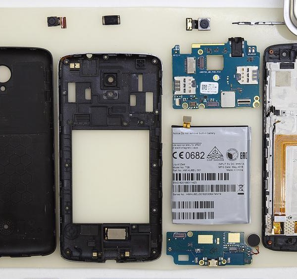
Related Reviews
Related Blog
Popular Questions

Acer CloudMobile A9 S500
I would like to know if you have the screen for the Armor 8?
george
M
Acer Liquid Z630
Where did I get charging stripe in which site
Maheshwar Handal14
M
Acer Liquid Z630
Charging sport I need t where did I get it in which site
Maheshwar Handal12
J
Acer Liquid Z630
Hello, how can i replace digitizer? Any video? Thank you. Hans
Jan Geryk18
Q
Acer Liquid Z530
very informative, thank you! although, I would like to know where the vibration motor is located
Qwem Lhjsi7Top instructions
Check our
Top Acer instructions most liked by readers
New instructions
Check our
New Acer brand instructions on vrm24.com