

⚠️️ Before disassembling, do not forget to turn your phone off.
Teardown difficulty:
Moderate
Moderate
Recommended tools


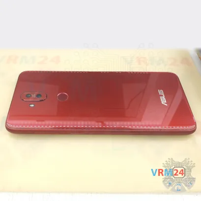
Disassembly/Repair of the mobile device Asus ZenFone 5 Lite ZC600KL (Asus ZenFone 5Q) with each step description and the required set of tools.

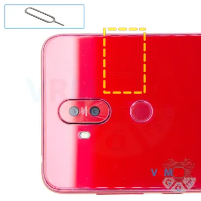


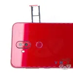

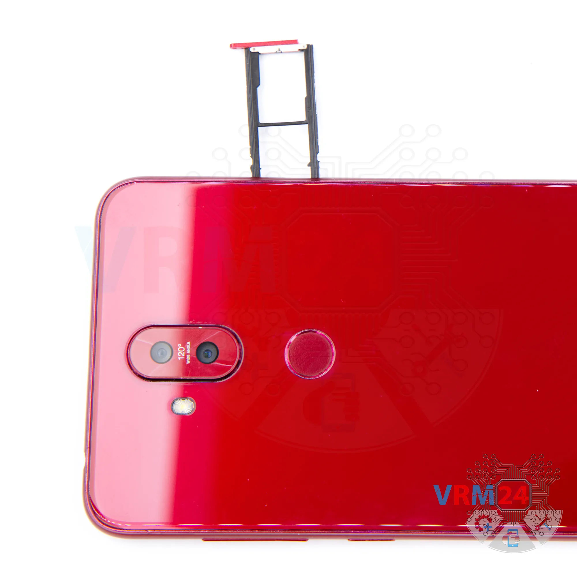
Step 2. Remove the tray
Use the ejection tool (aka Needle) or Paperclip. Push the tip all the way into the hole until the tray ejects, and then pull the tray of SIM and Memory card (Micro SD) out.
⚠️️ Pay attention! The tool must be inserted into a hole on the edge of the phone's housing. Do not press too hard. It may break the tray eject mechanism.

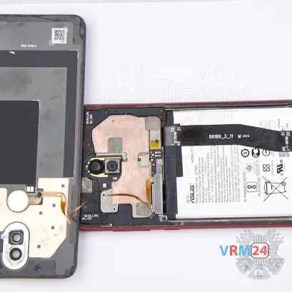

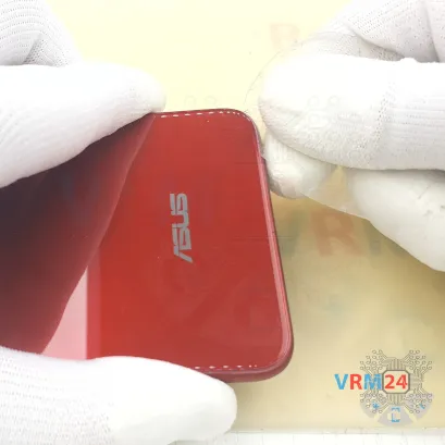

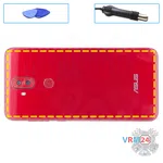


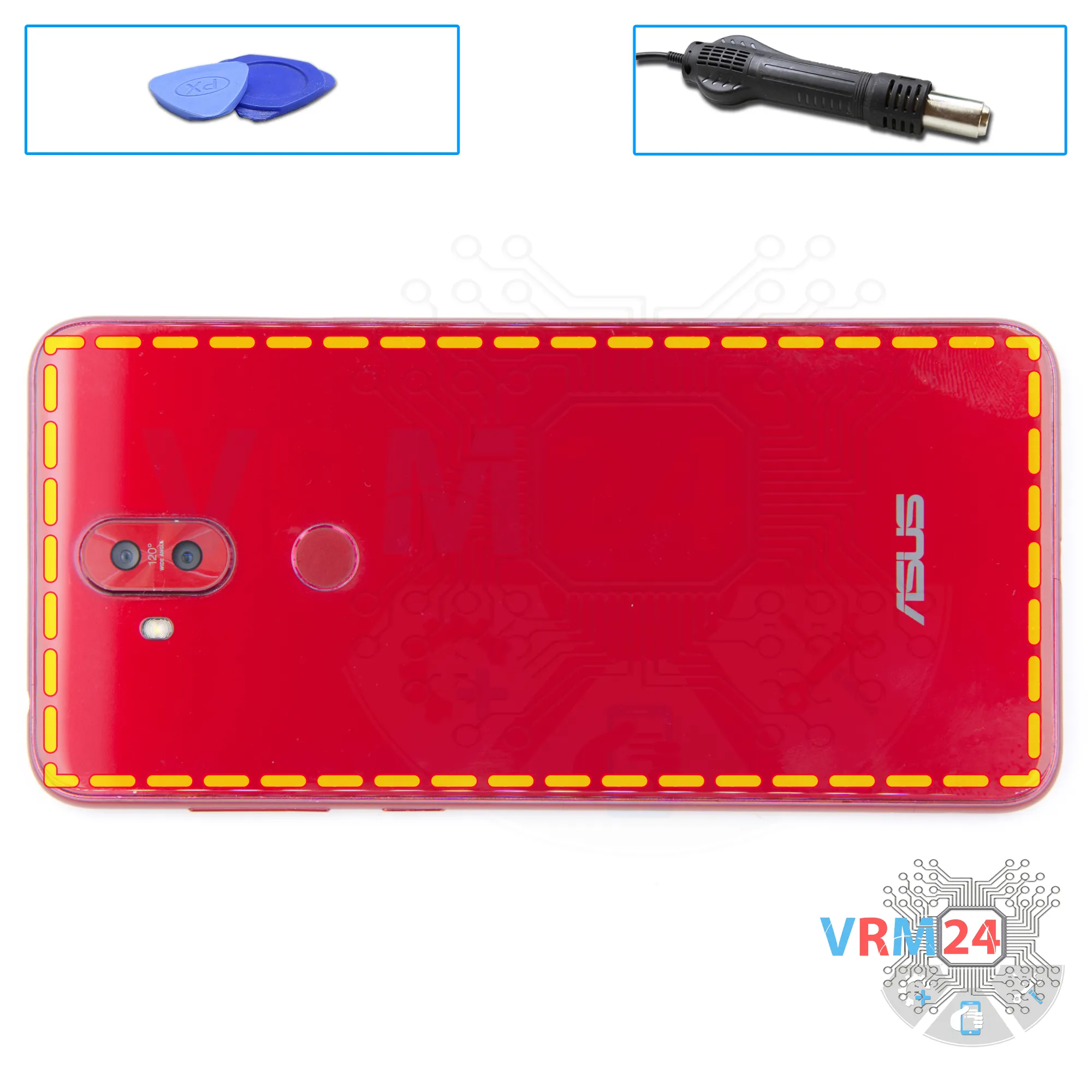
Step 3. Open the back cover
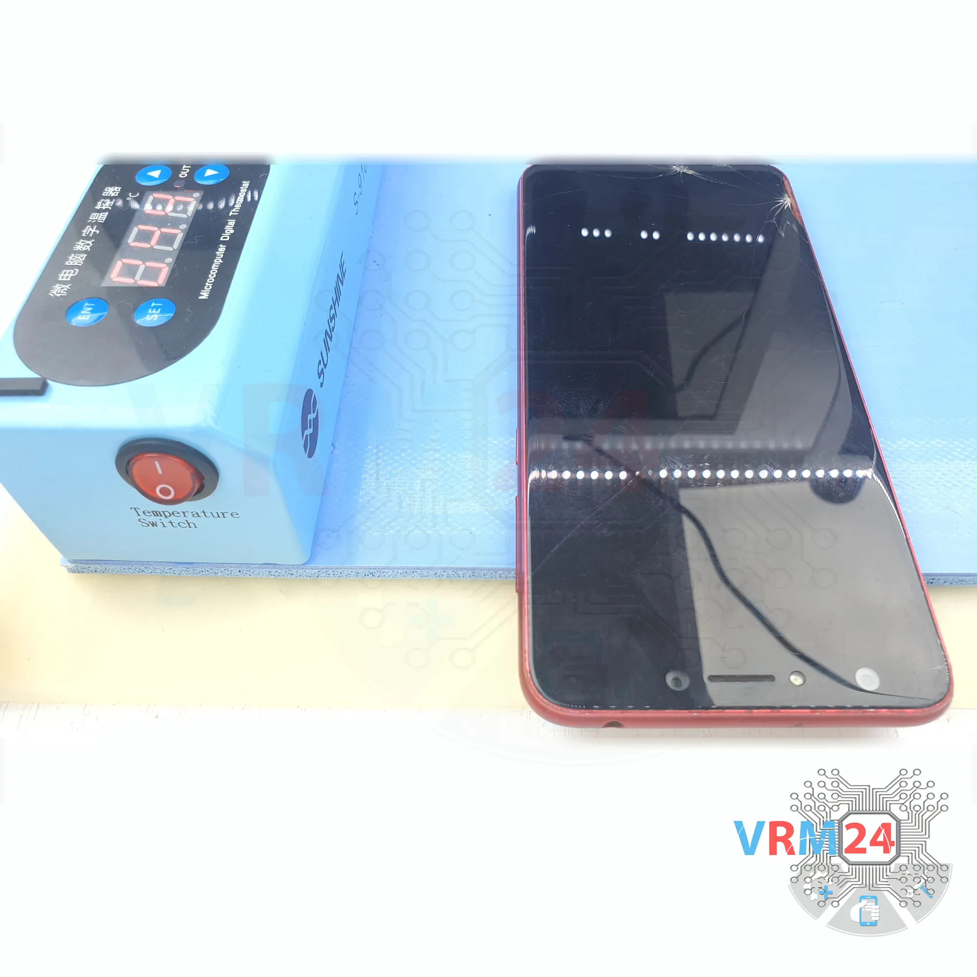
We recommend using a special heating device such as a separator machine, heat gun, or heating mat. It will simplify the process. You can use a home hairdryer, but you will have to make a nozzle by hand or have a suitable one in the kit to gently heat and concentrate the heat flow in the right place.
ℹ️️ The surface of the back cover must be heated to soften the adhesive underneath. The approximate heating temperature is 50° C / 125° F.
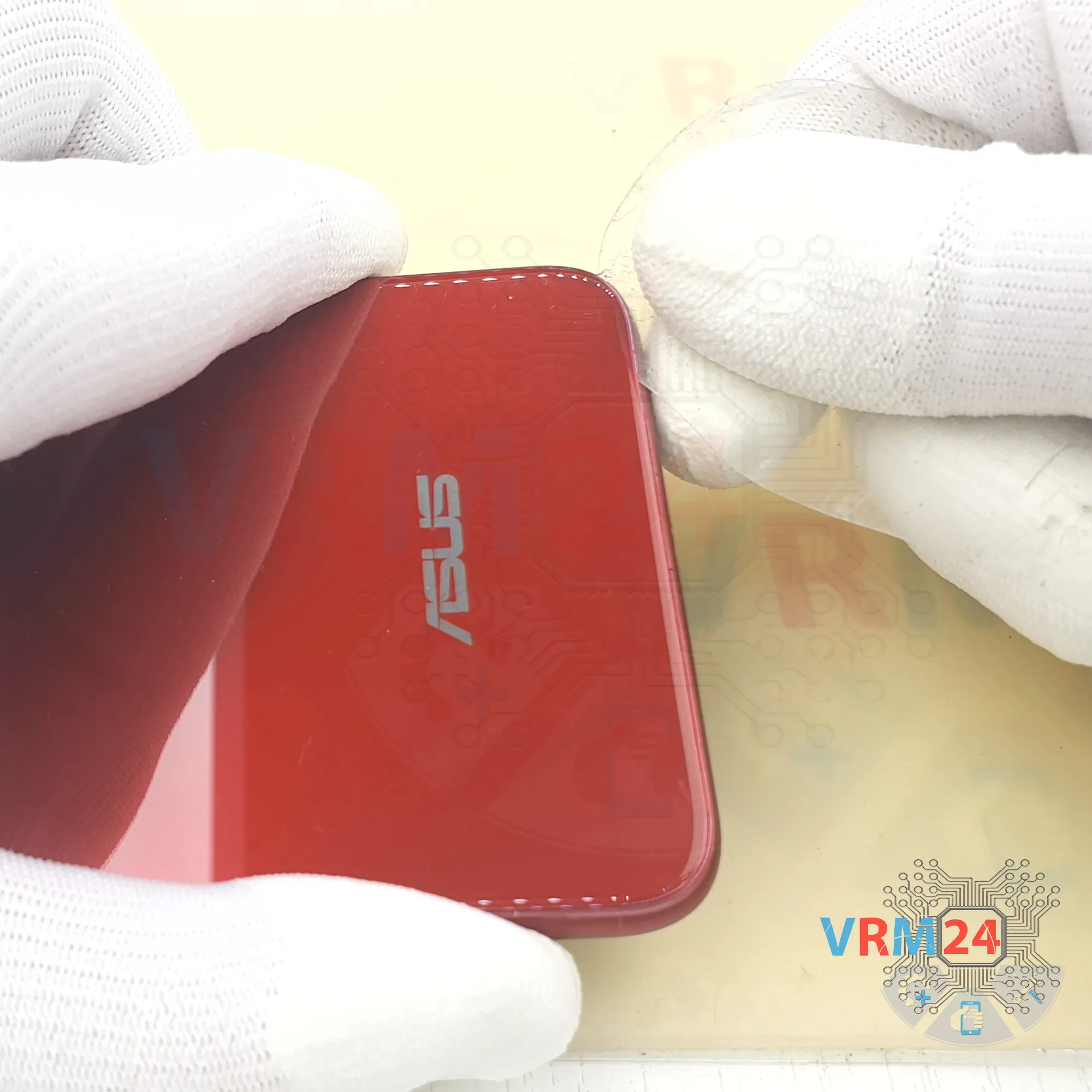
Use a thin plastic film or pick for separation. To facilitate the process, you can use isopropyl alcohol. It is often the most difficult to pass the tool between the parts to be divided. Choose the far edge from the FFC cables or buttons.
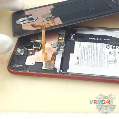
Do not use a lever or any force for separation that could damage the elements inside.
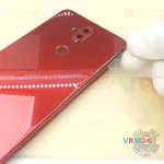
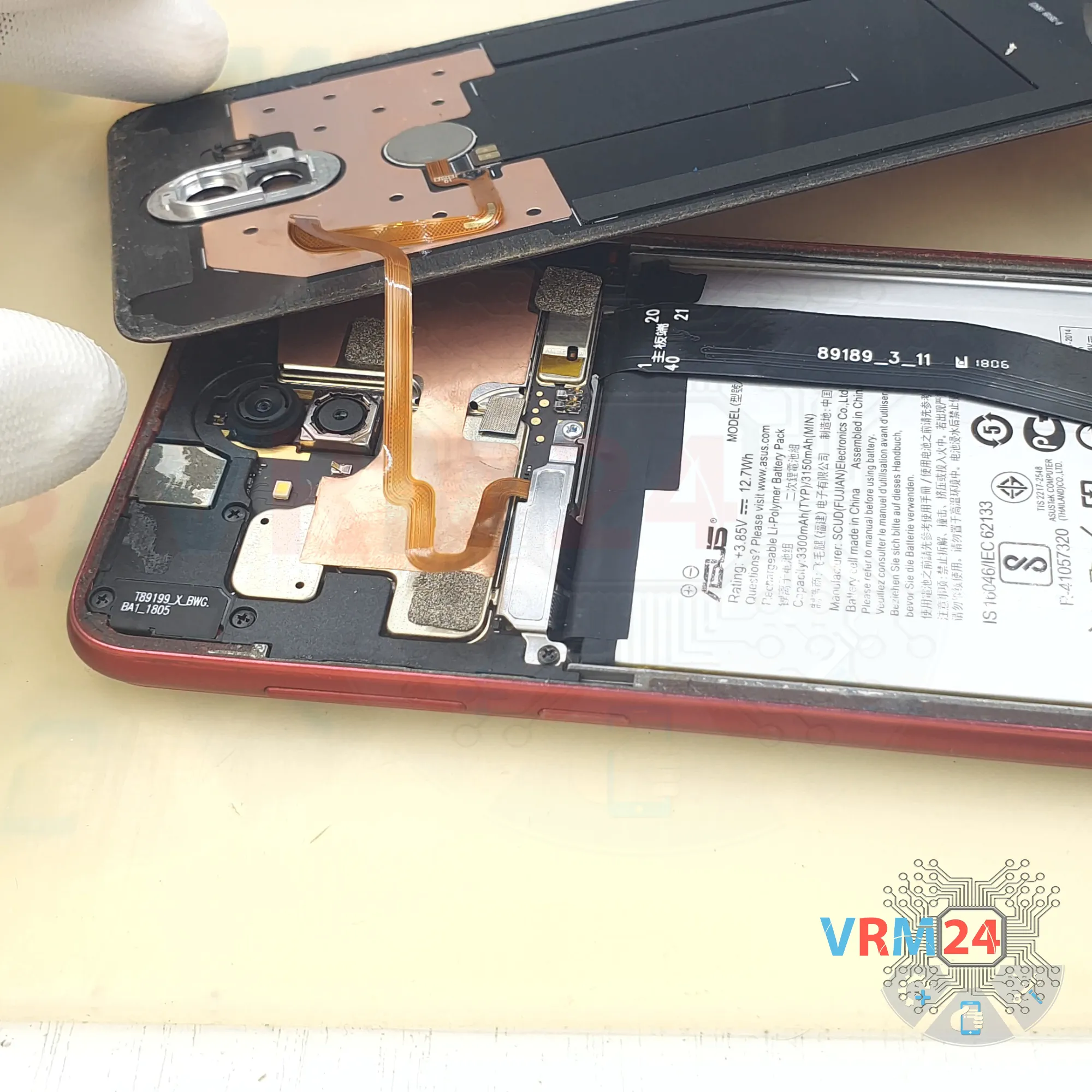
⚠️️ Pay attention to the fingerprint sensor cable! The cable connects the fingerprint sensor on the back cover to the motherboard.

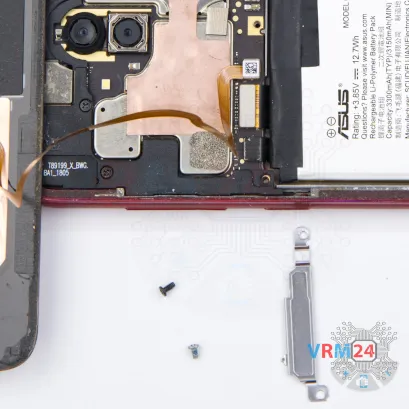

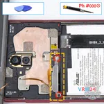


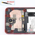
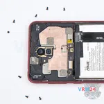
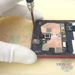
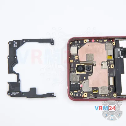
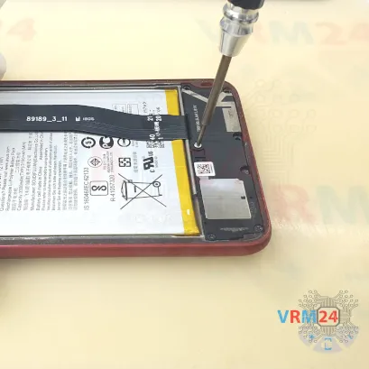
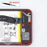
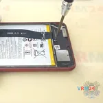
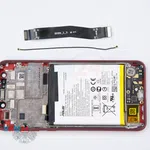
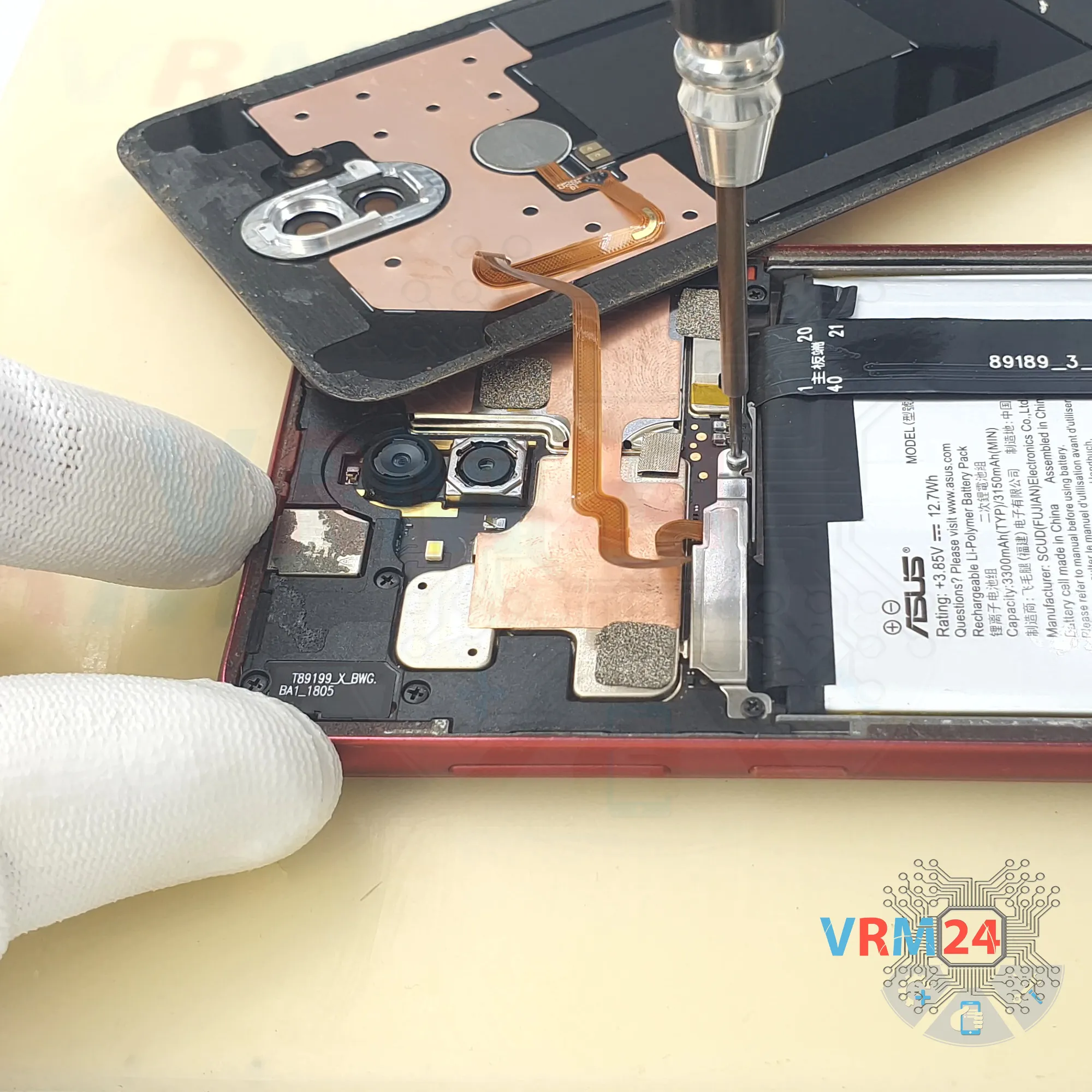
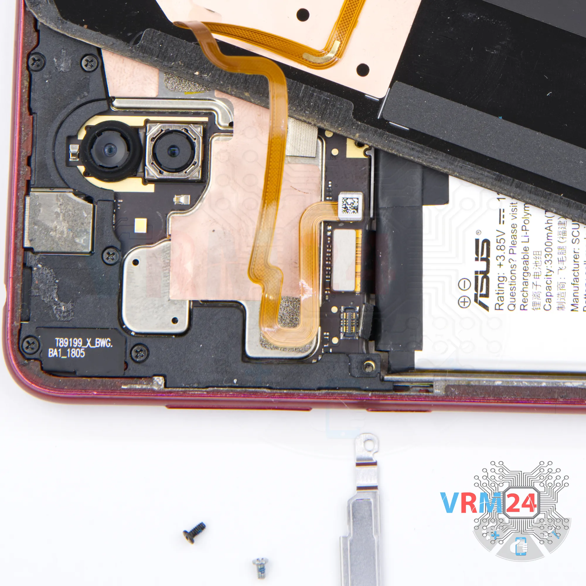
Step 4. Remove the bracket
Using a screwdriver (Phillips 1.5 mm PH #000), unscrew the two screws and remove the bracket holding the connectors.


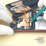
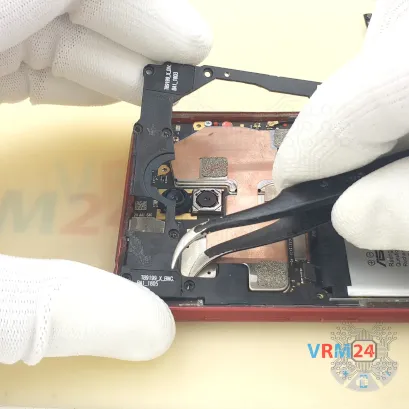
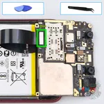
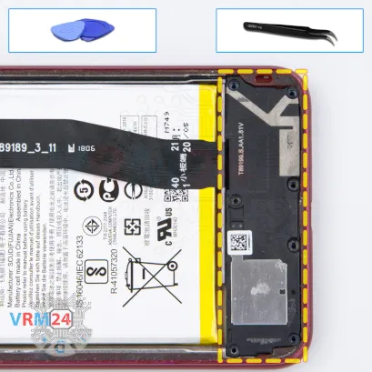
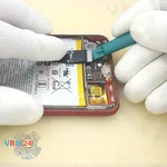
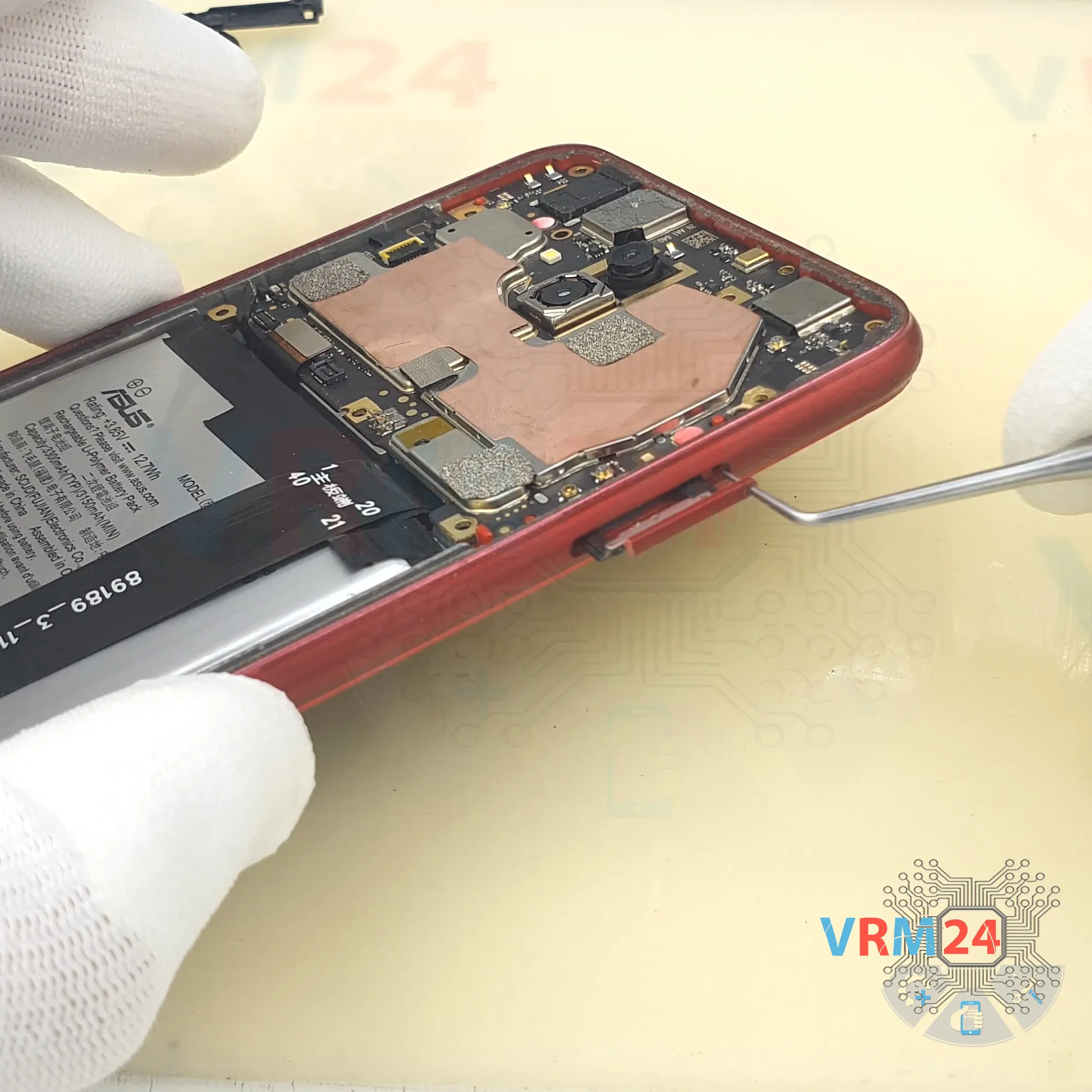
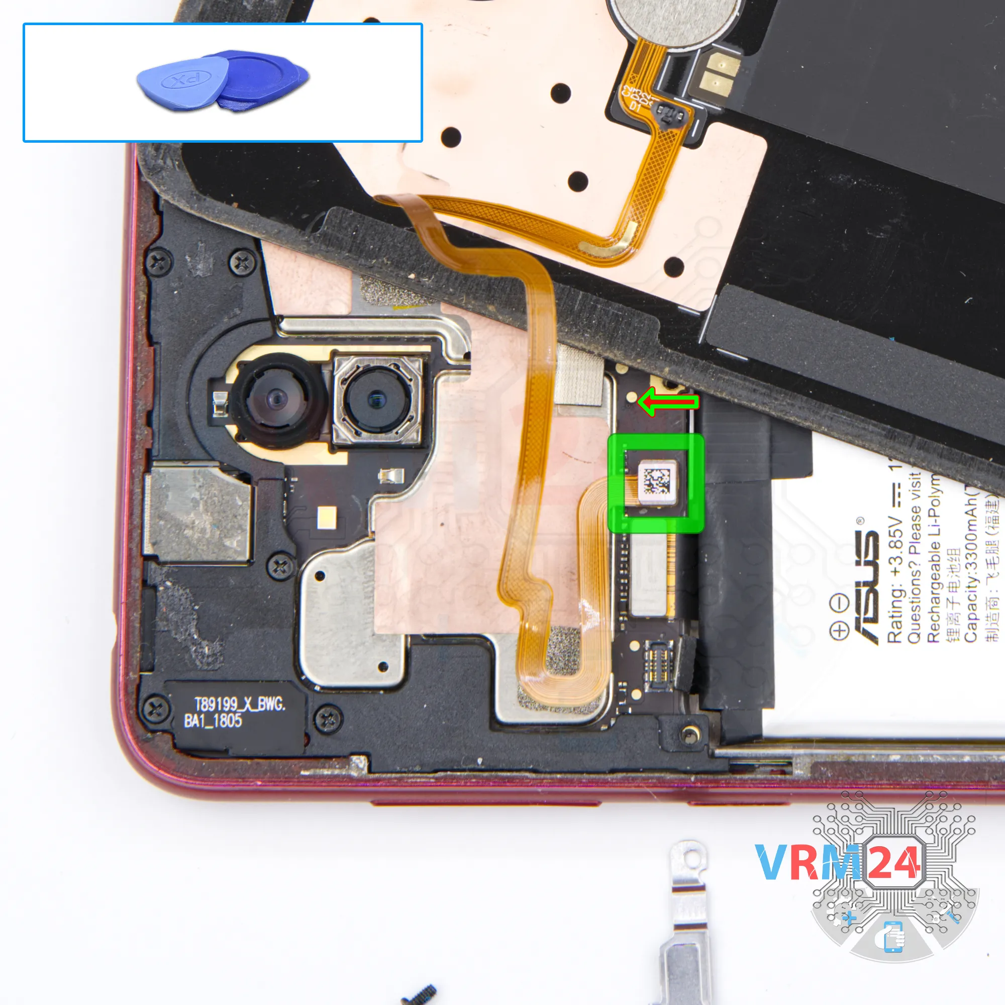
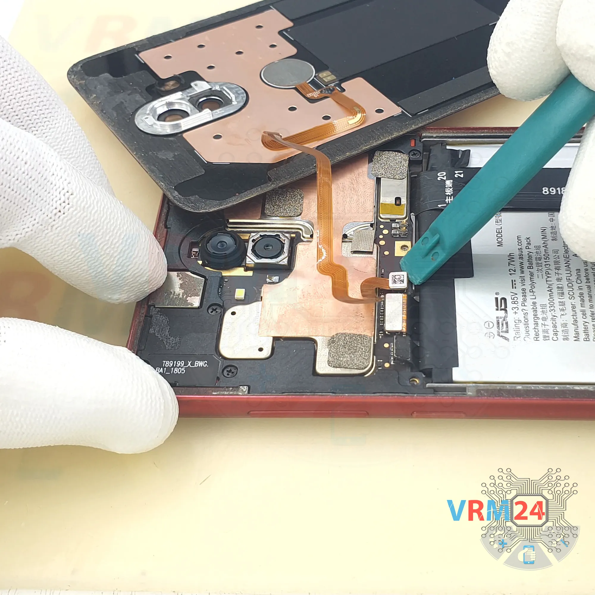
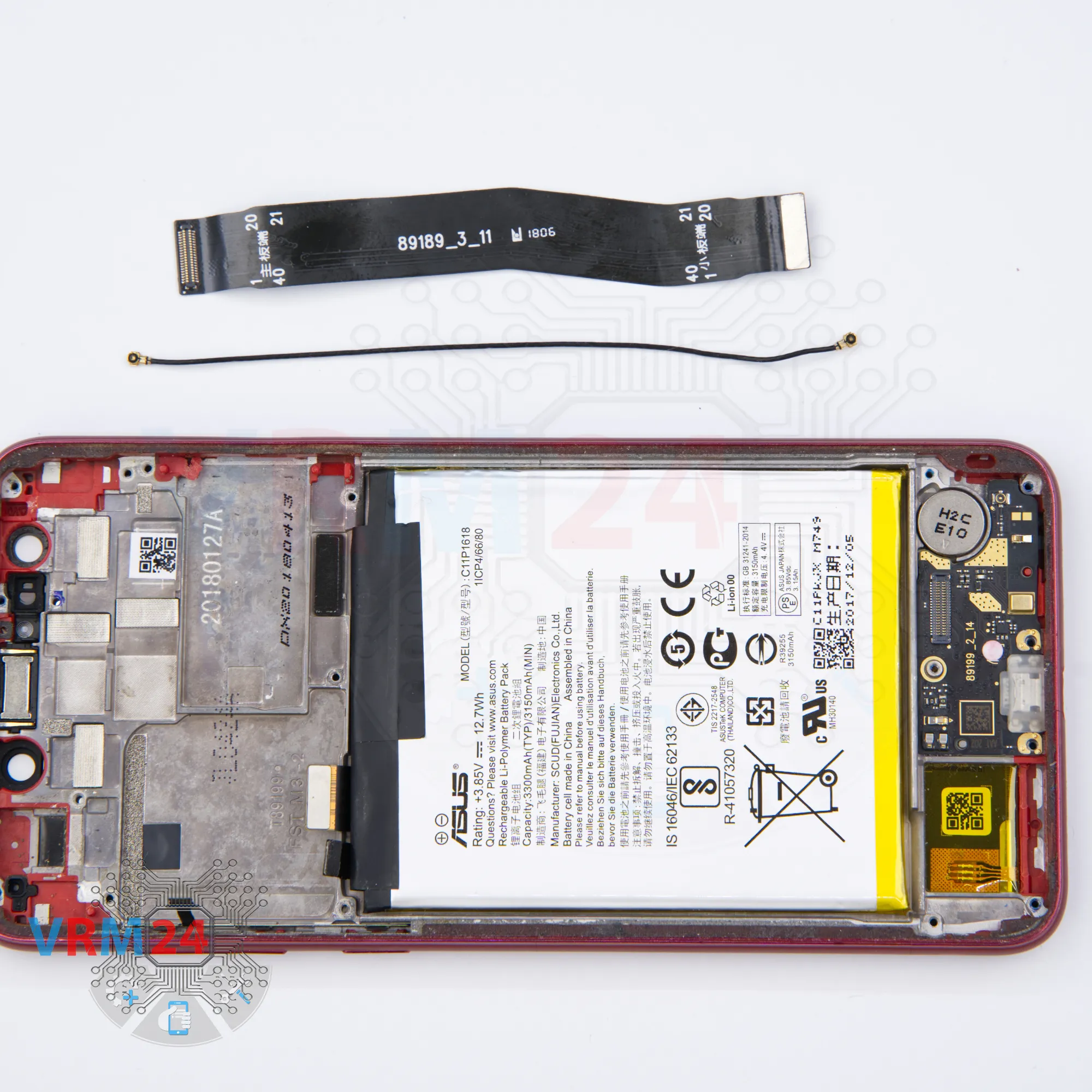
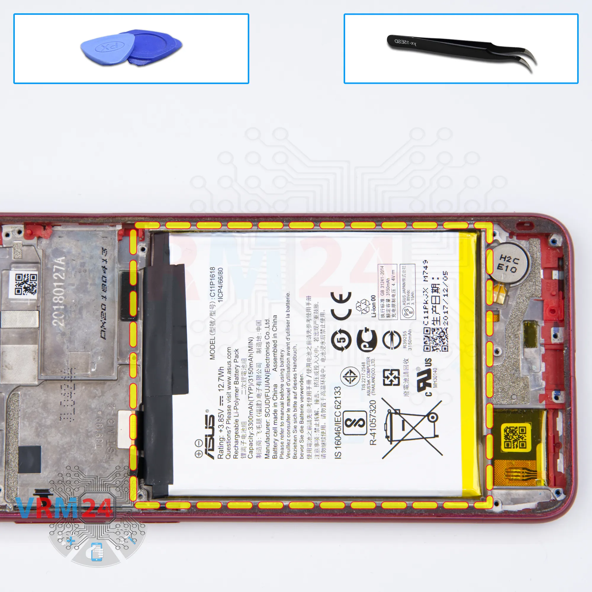
Step 5. Disconnect the battery connector
Disconnect the battery connector as soon as possible. It is better to use a non-metal or plastic tool to avoid any damage.
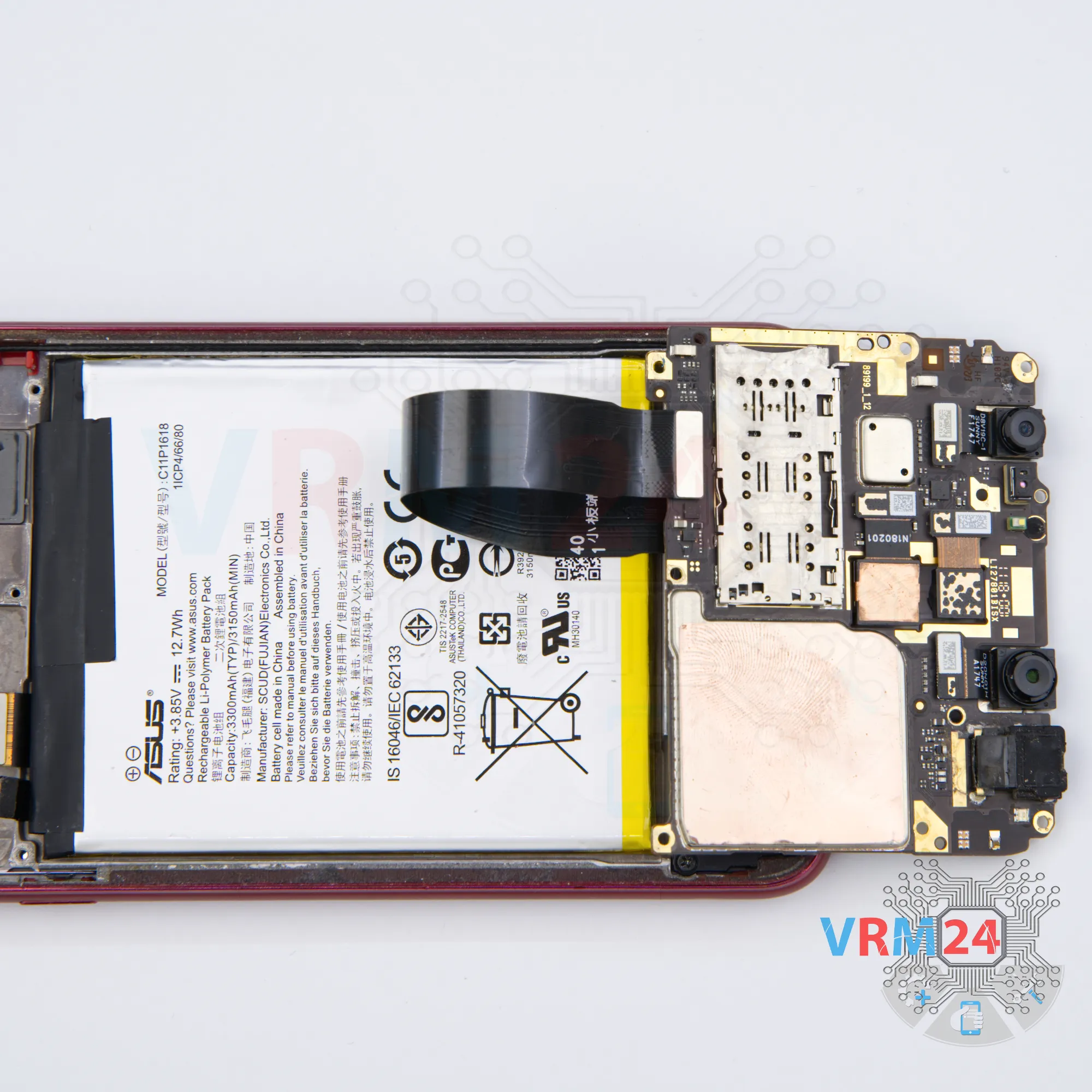
ℹ️️ The Alcatel 1S (2019) 5024D model has a battery C11P1618 with 3300 mAh capacity (aka rechargeable battery).
⚠️️ It is highly recommended to disconnect the connector to avoid possible short circuits during disassembly.


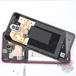
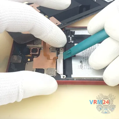
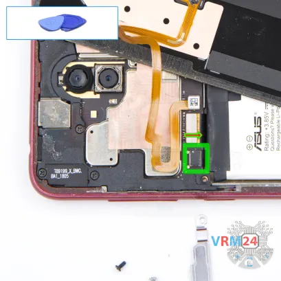
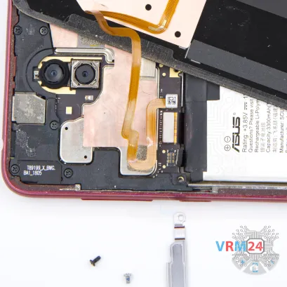
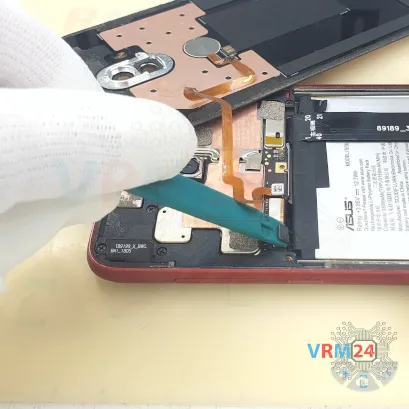
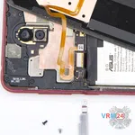
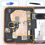
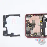
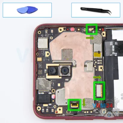
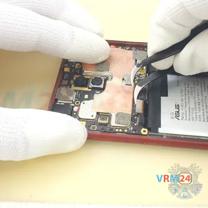
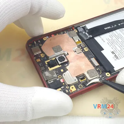
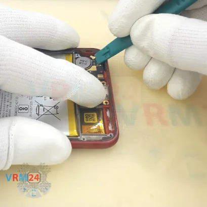
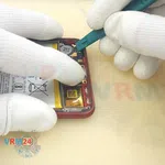
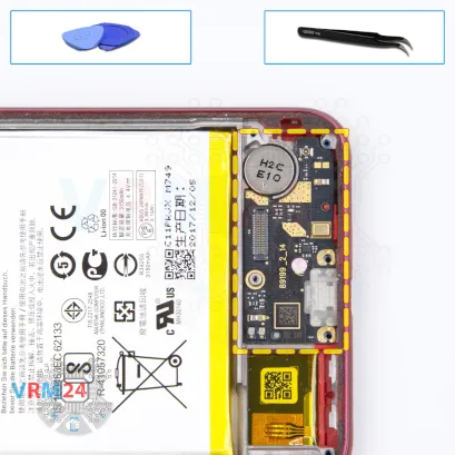
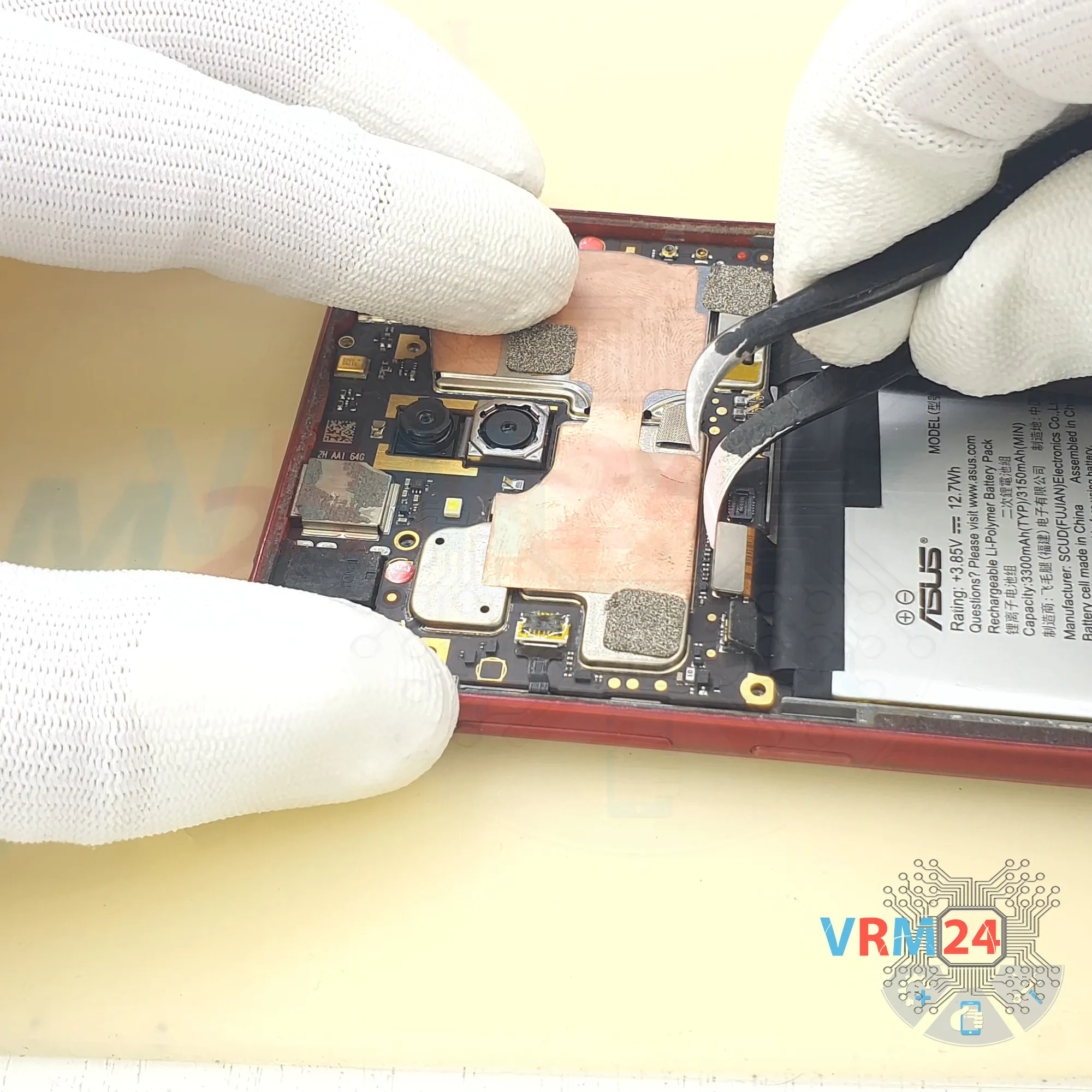
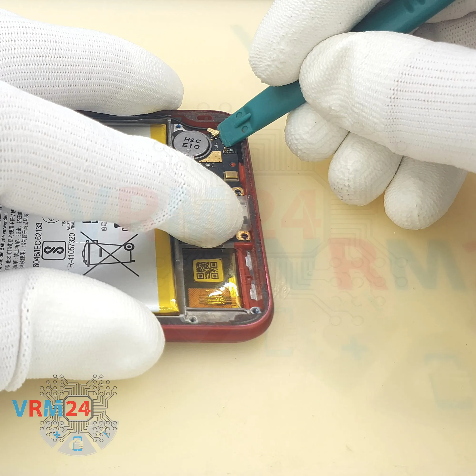
Step 6. Disconnect the connector
Disconnect the connector and remove the cover with a fingerprint sensor and NFC tag.


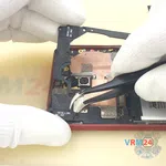


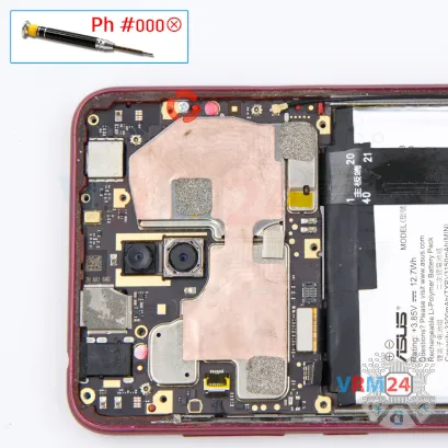
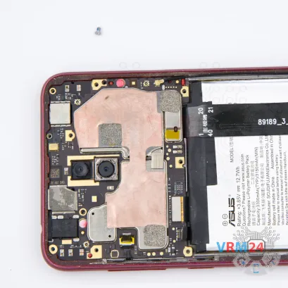

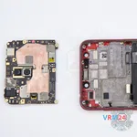
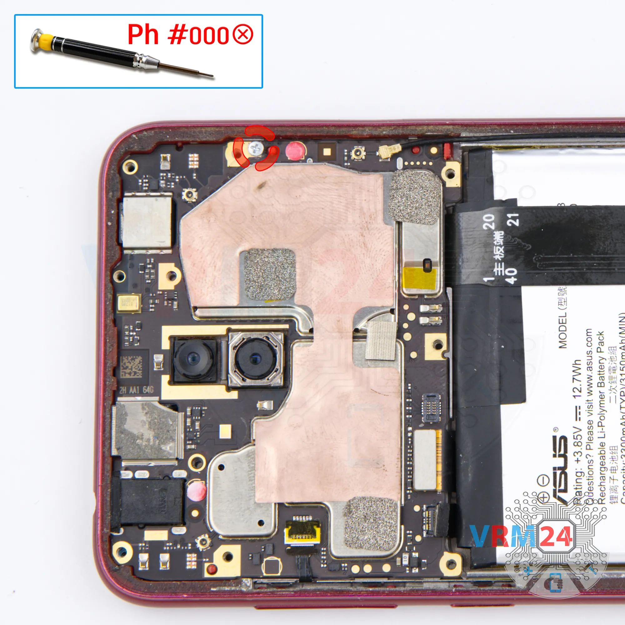
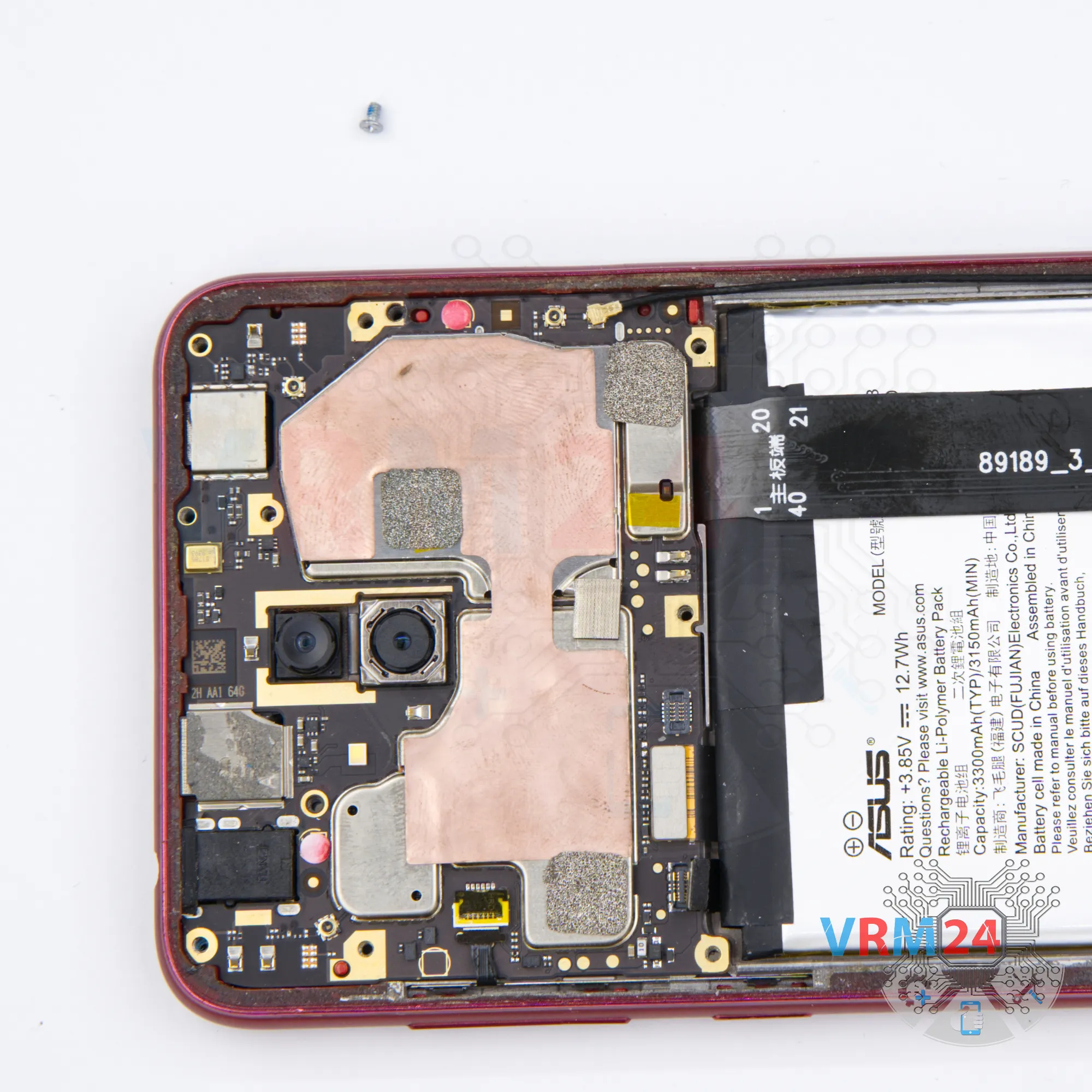
Step 10. Unscrew one screw
Using a screwdriver (Phillips 1.5 mm PH #000), unscrew one screw securing the motherboard.
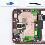
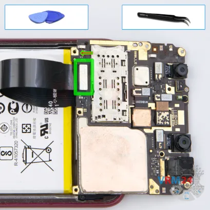
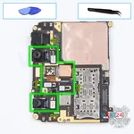
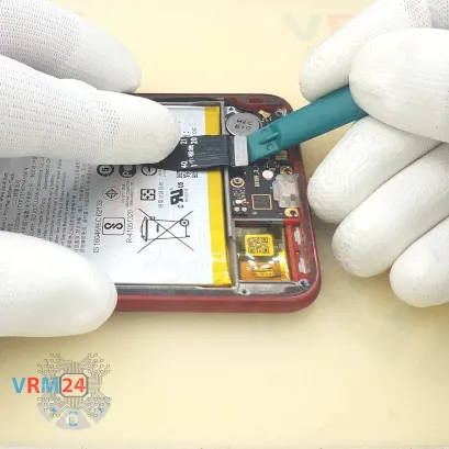
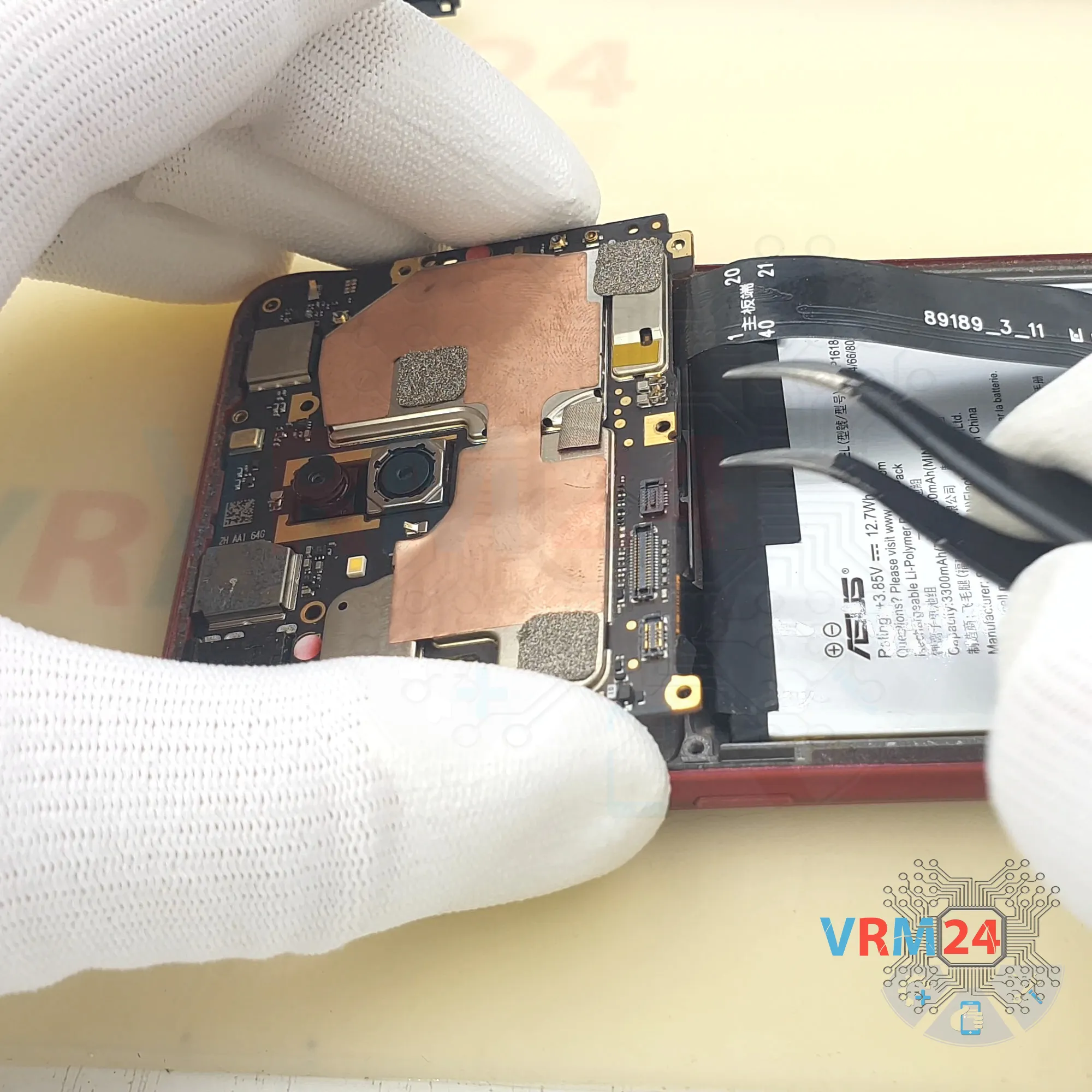
Step 11. Disconnect the connectors
Pry up the connectors of the side buttons cable, display module cable, coaxial cable.
⚠️️ Be careful when removing the cables from the connectors, the cables are pretty thin, and it is easy enough to break them or damage the contact tracks inside.


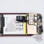
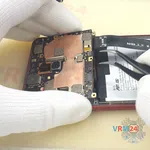
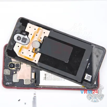
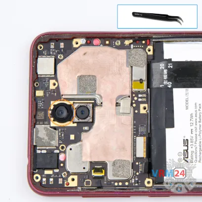
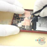
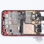
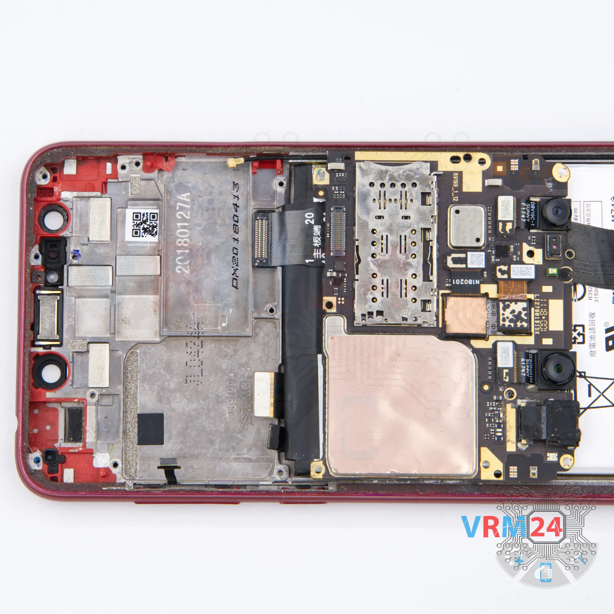
Step 12. Turn over the PCB
Carefully detach the printed circuit board and turn it over. There is no need to use a lever or try to reach the circuit board by force. Make sure that nothing is getting in the way or holding the circuit board.
The motherboard, also, may be attached with attachments like latches or hooks, be careful.
⚠️️ Do not bend the circuit board when removing it or push tools under it. Unbeknownst to yourself, you can damage components or cables from the inside.

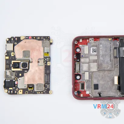
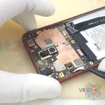
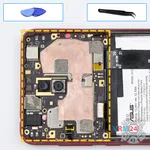
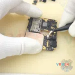
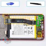
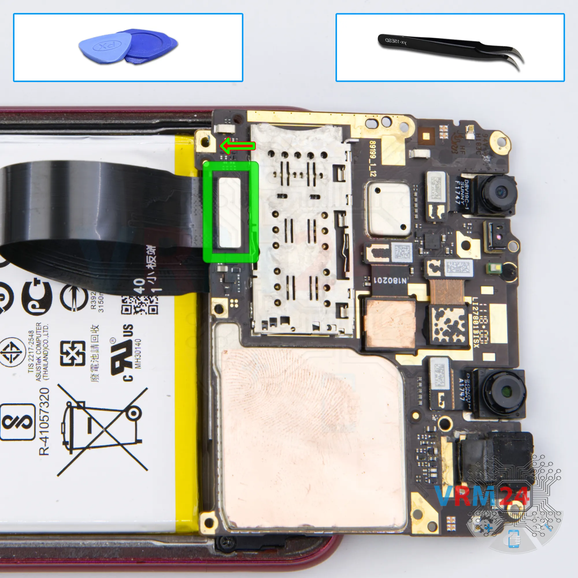
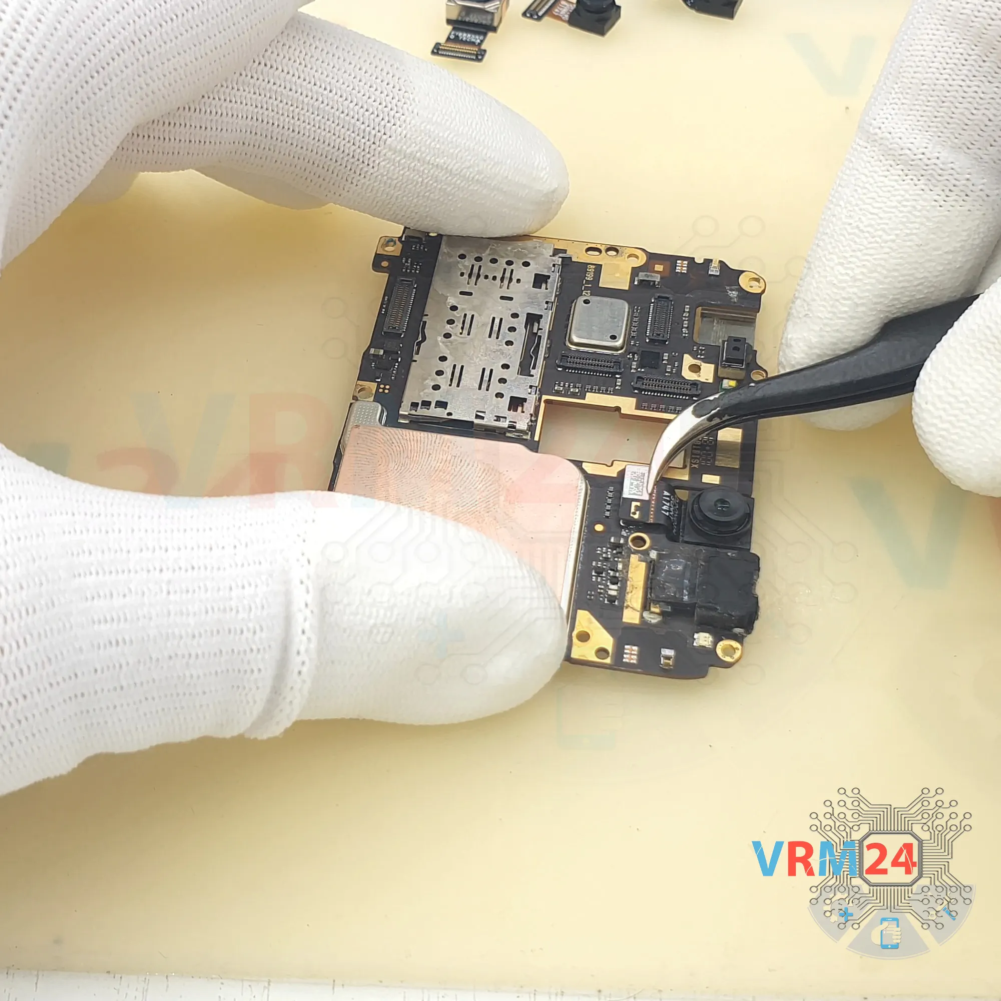
Step 13. Disconnect the connector
Disconnect the inter-board cable connector and remove the motherboard.
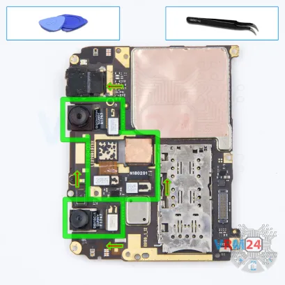
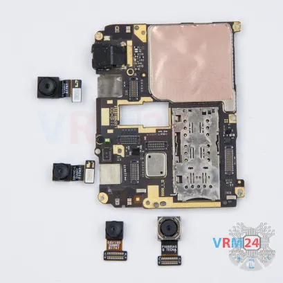
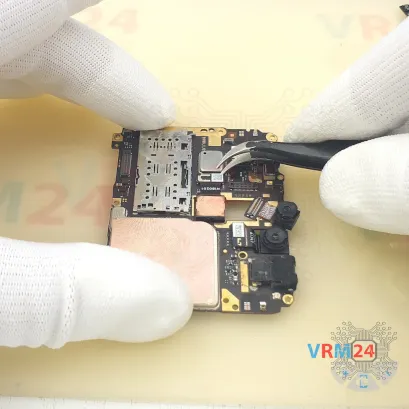
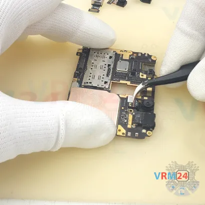
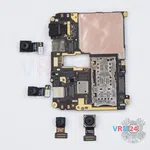

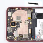
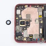
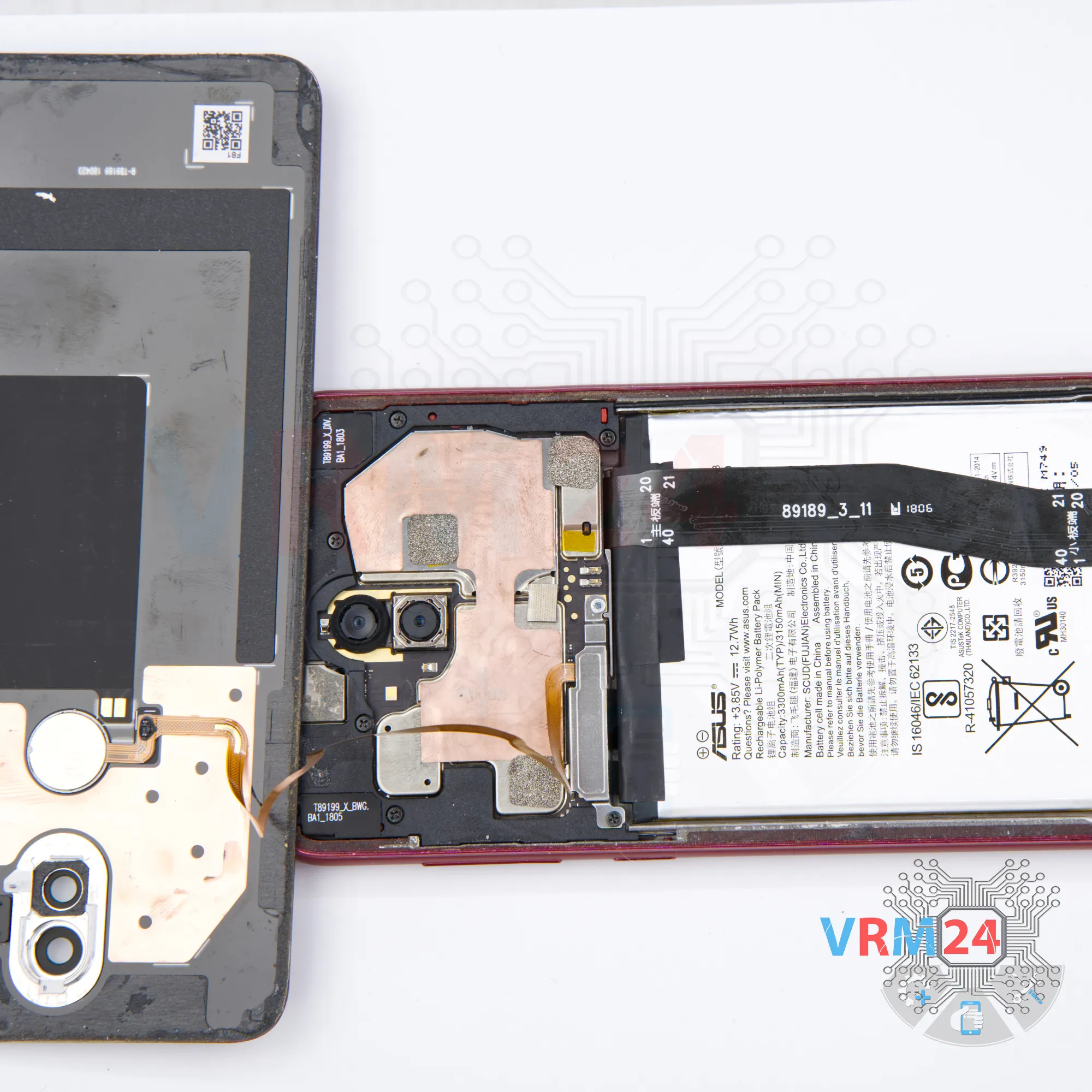
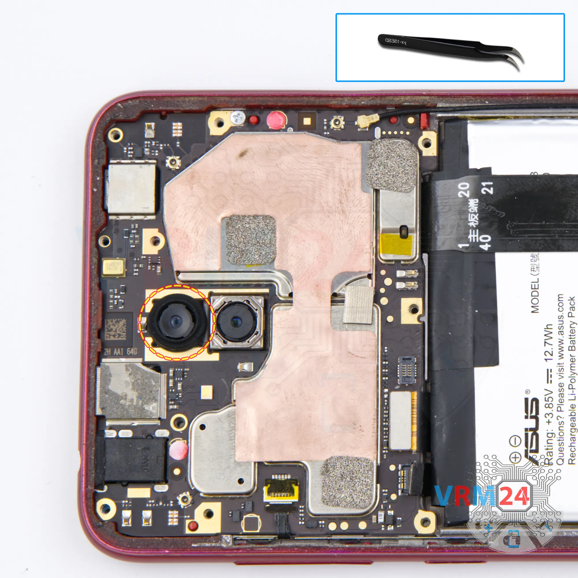
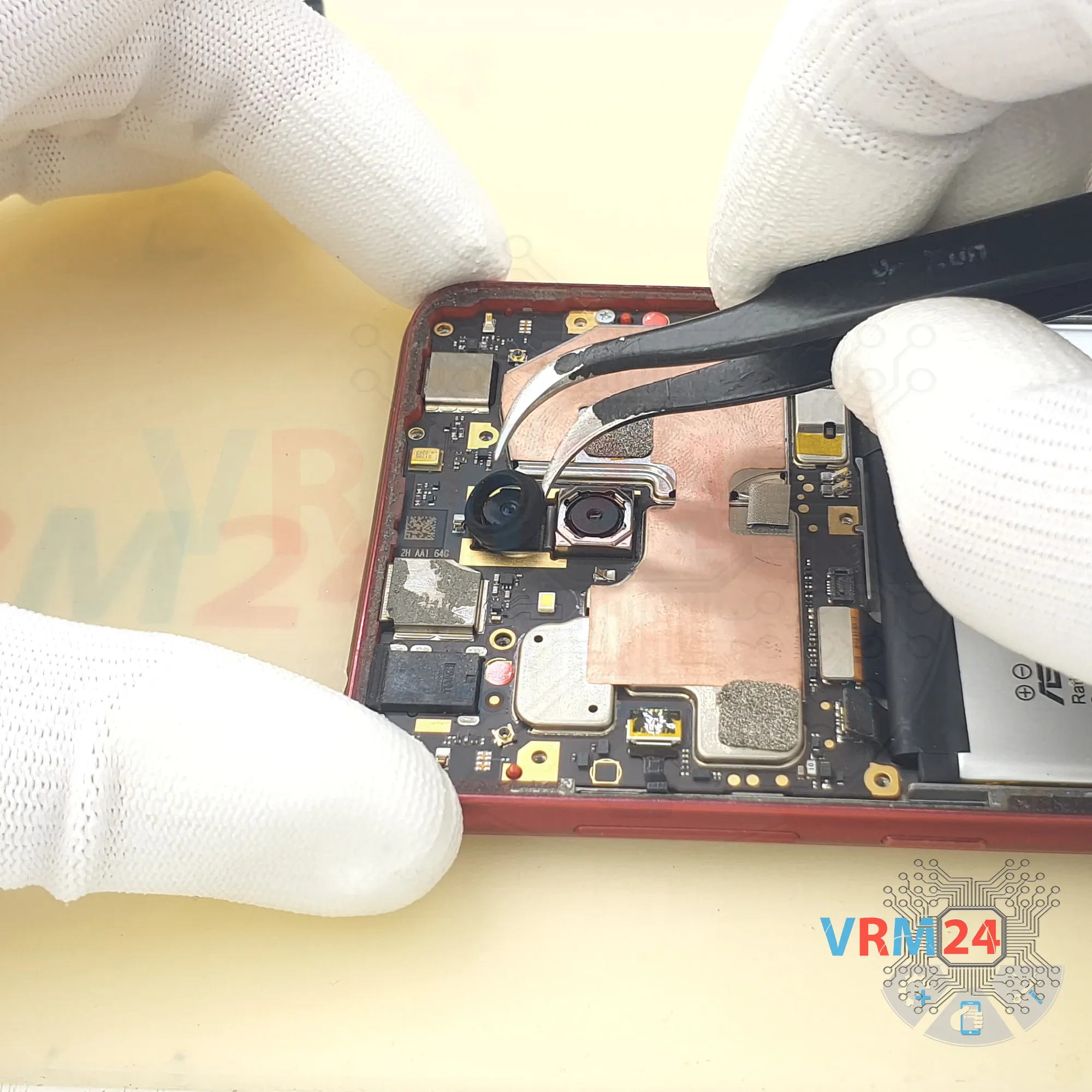
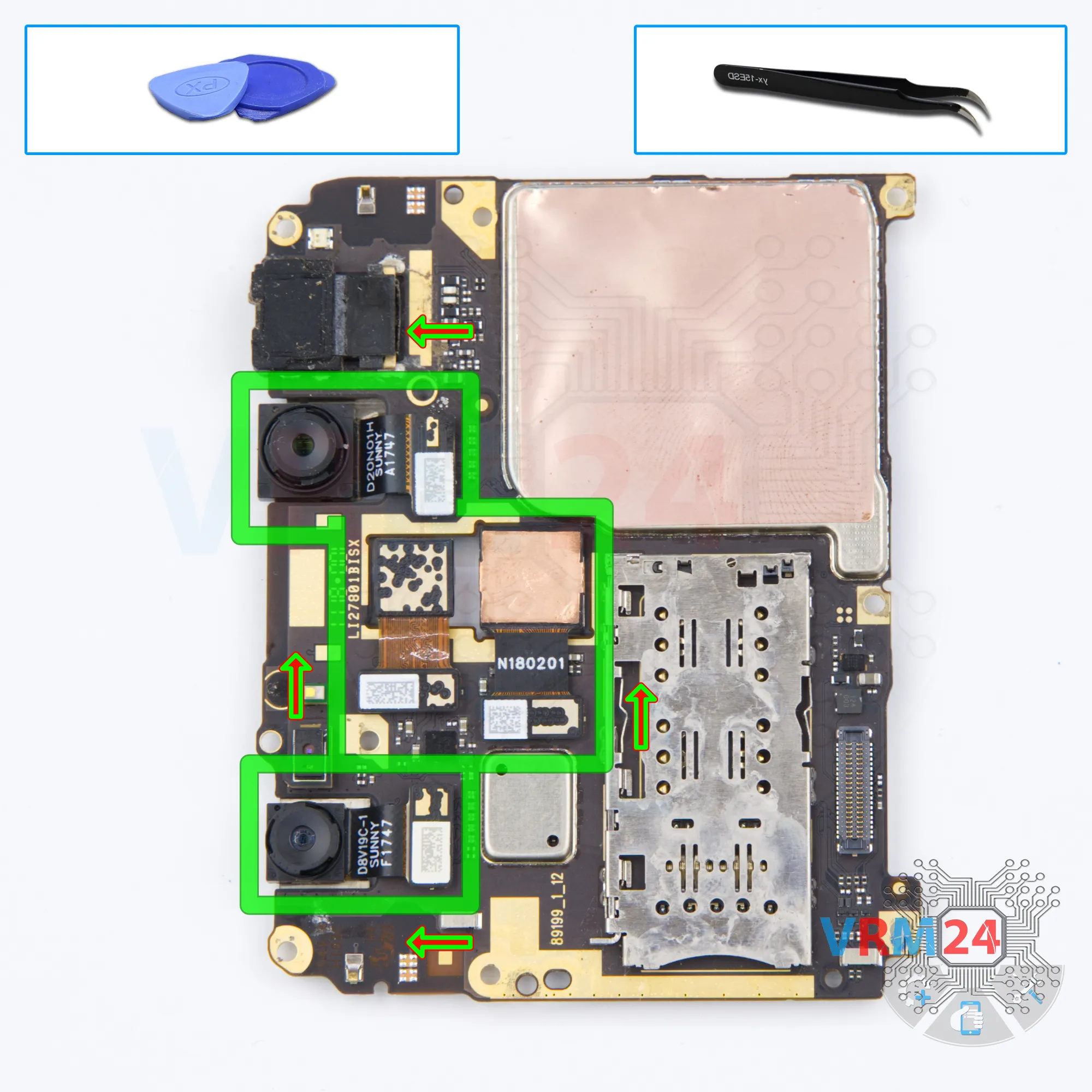
Step 14. Remove the cameras
Pry up the connectors and remove the two rear cameras and two front cameras.
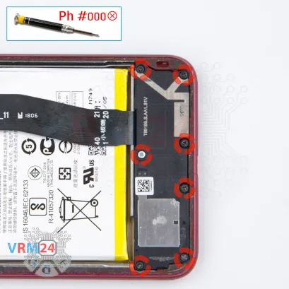


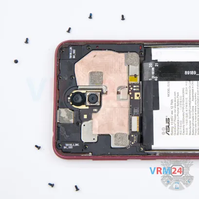
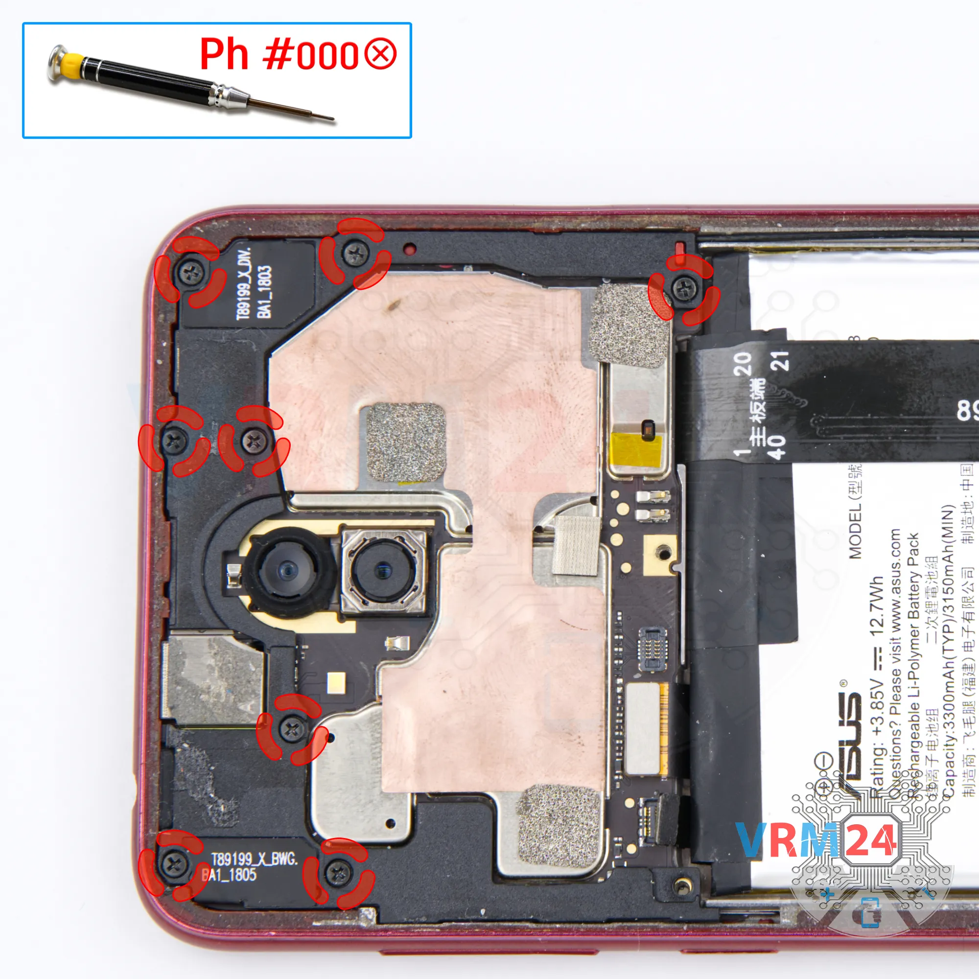
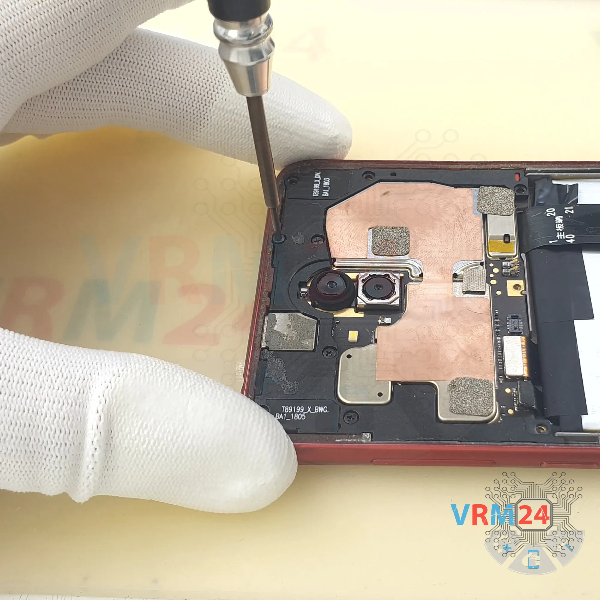
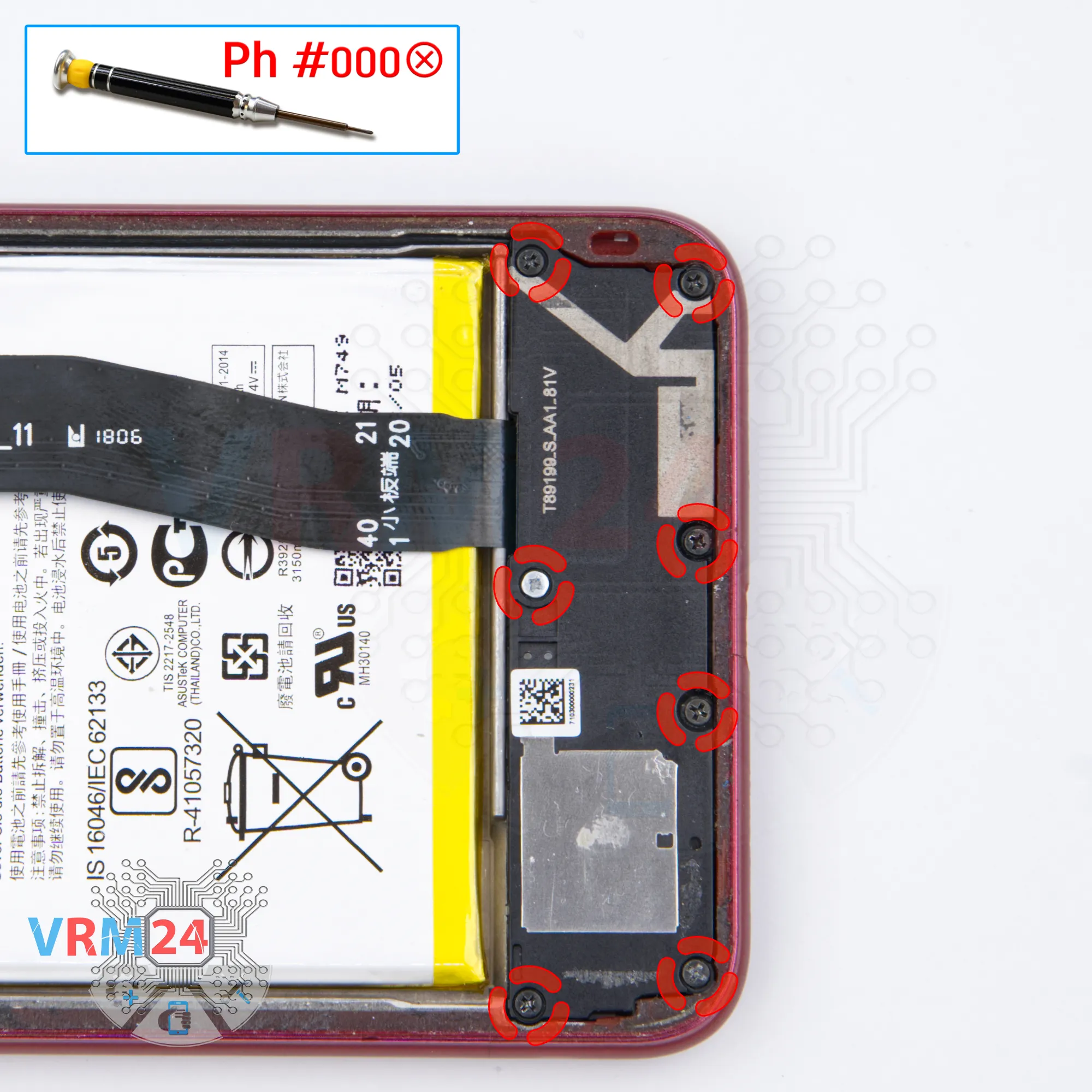
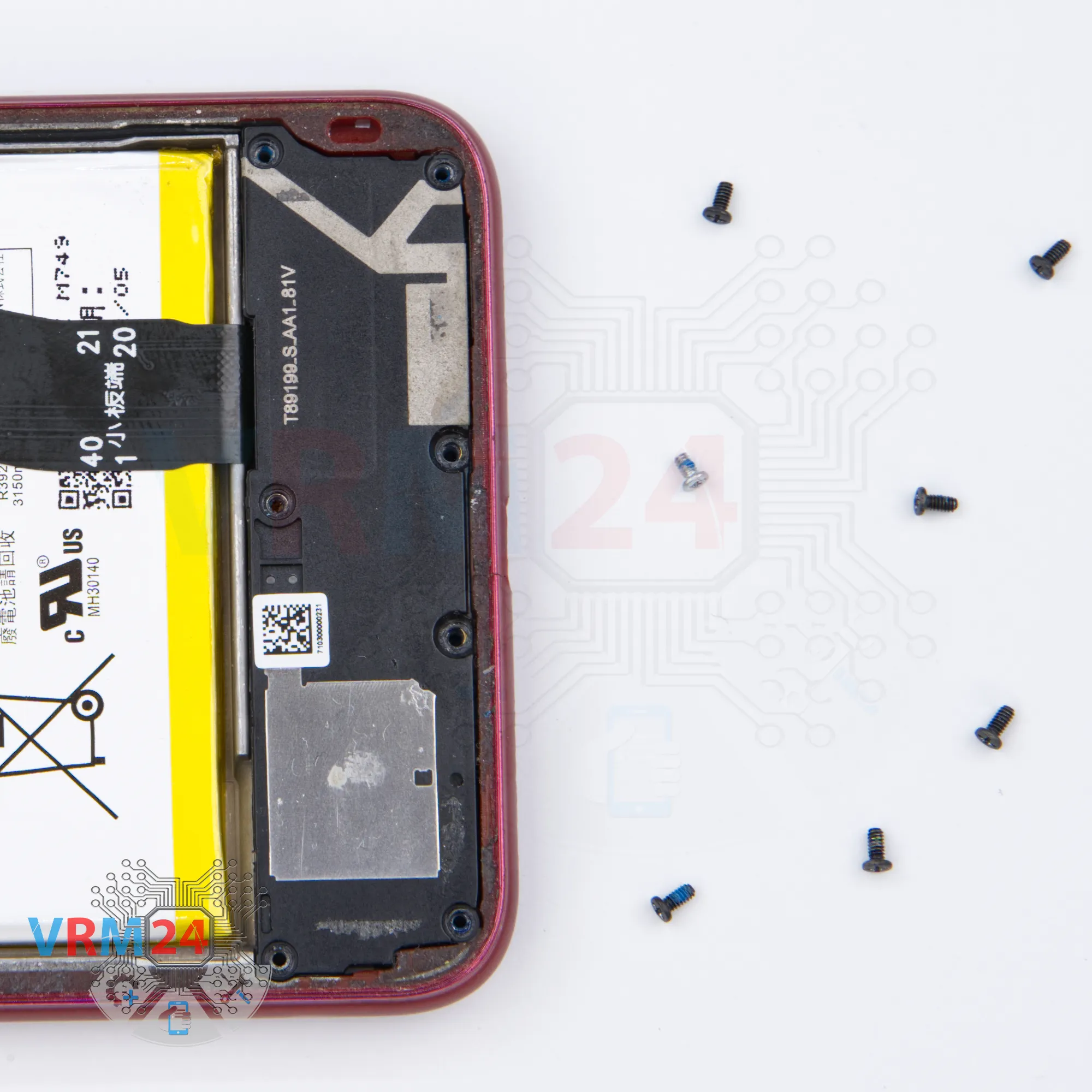
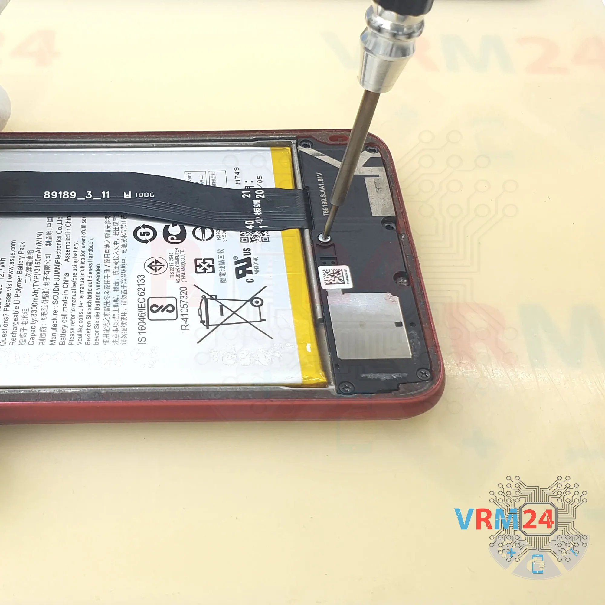
Step 15. Unscrew the screws
Using a screwdriver (Philips 1.5 mm PH #000), unscrew the seven screws.
The screws are different: ℹ️️ Be sure to note the location of the screws before disassembling. When assembling the device, screwing the screw in the wrong place may damage the device or its parts. To avoid damage, the removed screws and individual pieces (as gaskets or brackets) must be laid out in the appropriate order, or the screws and their holes in the phone must be marked with colored markers.
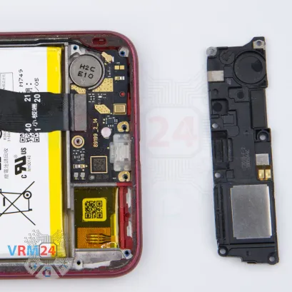


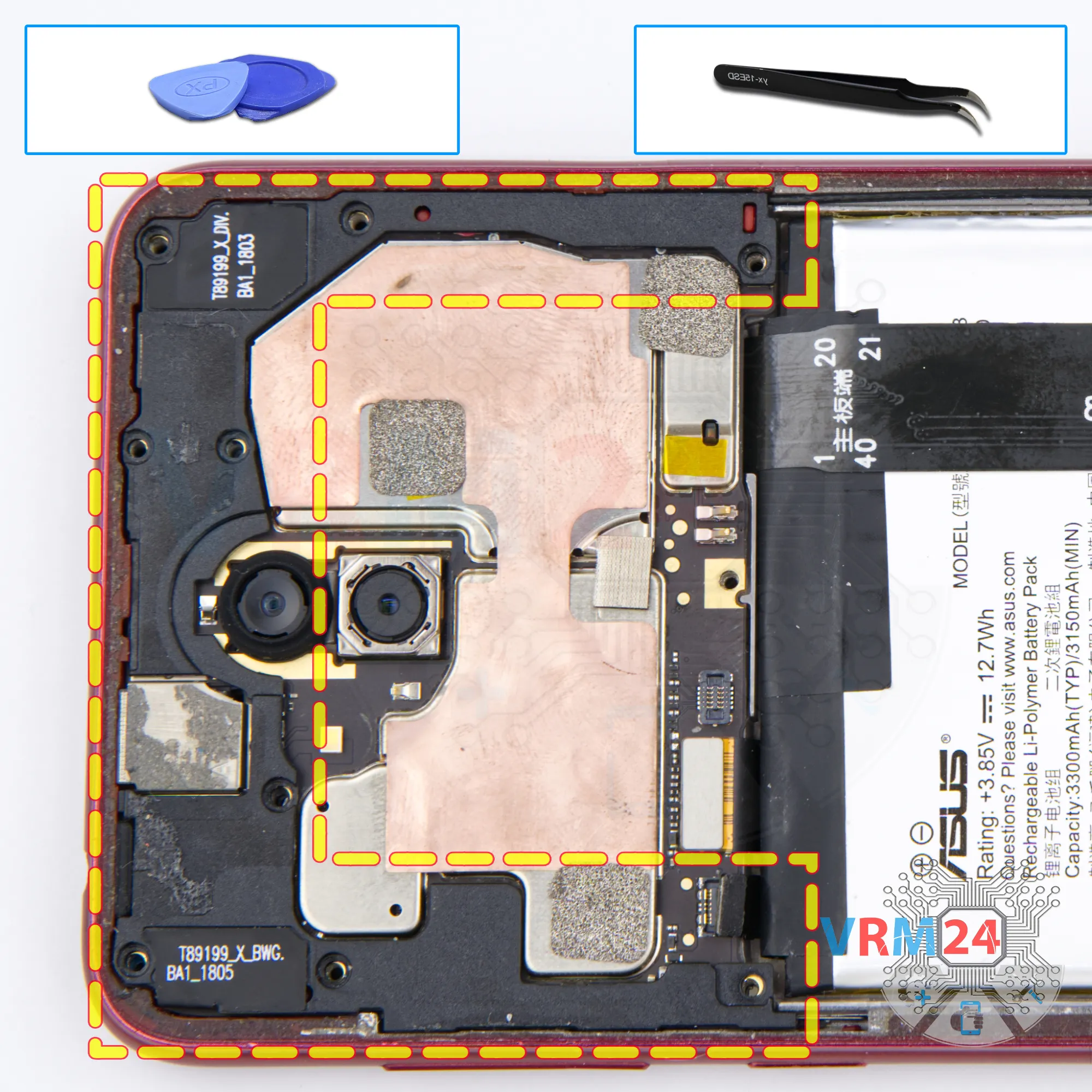
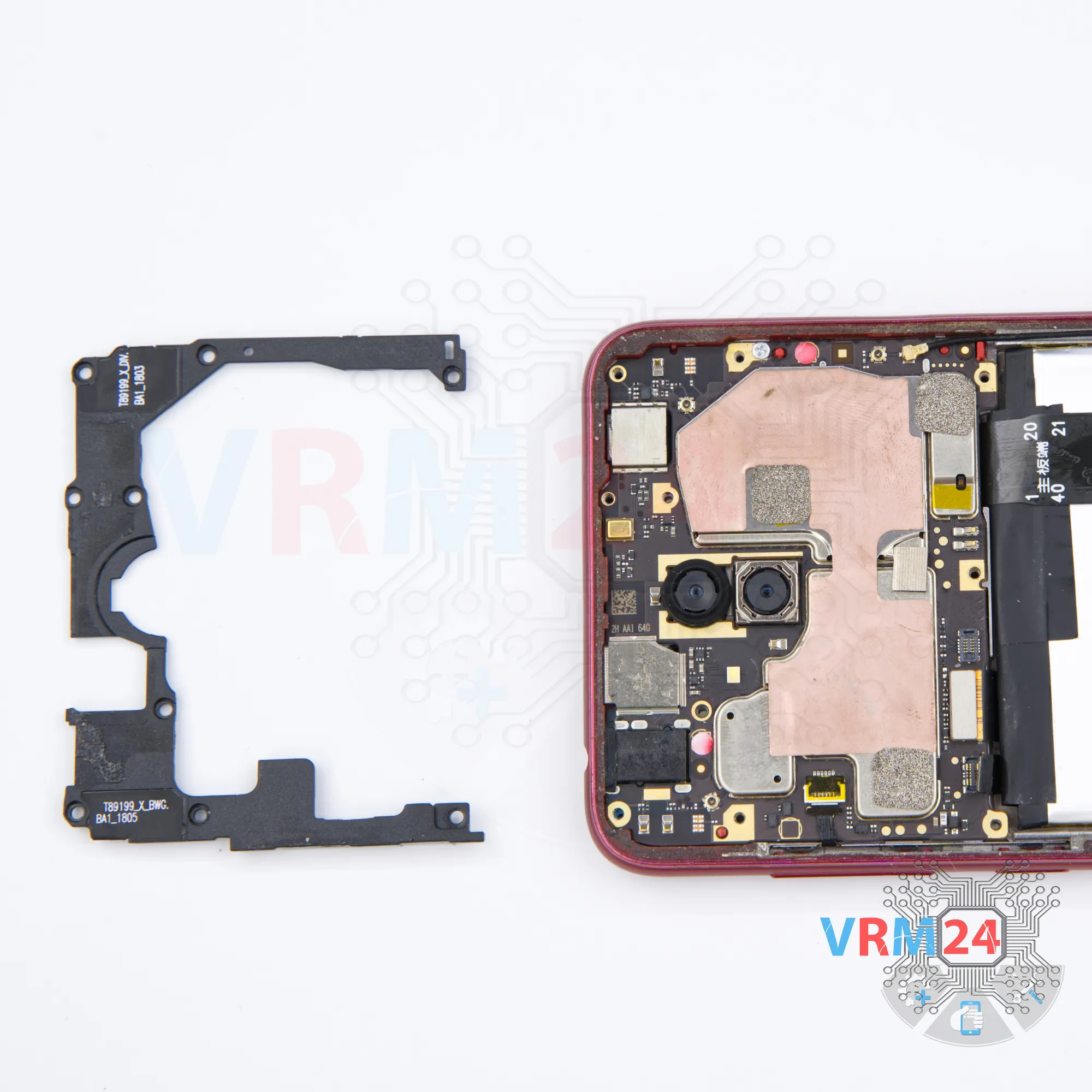
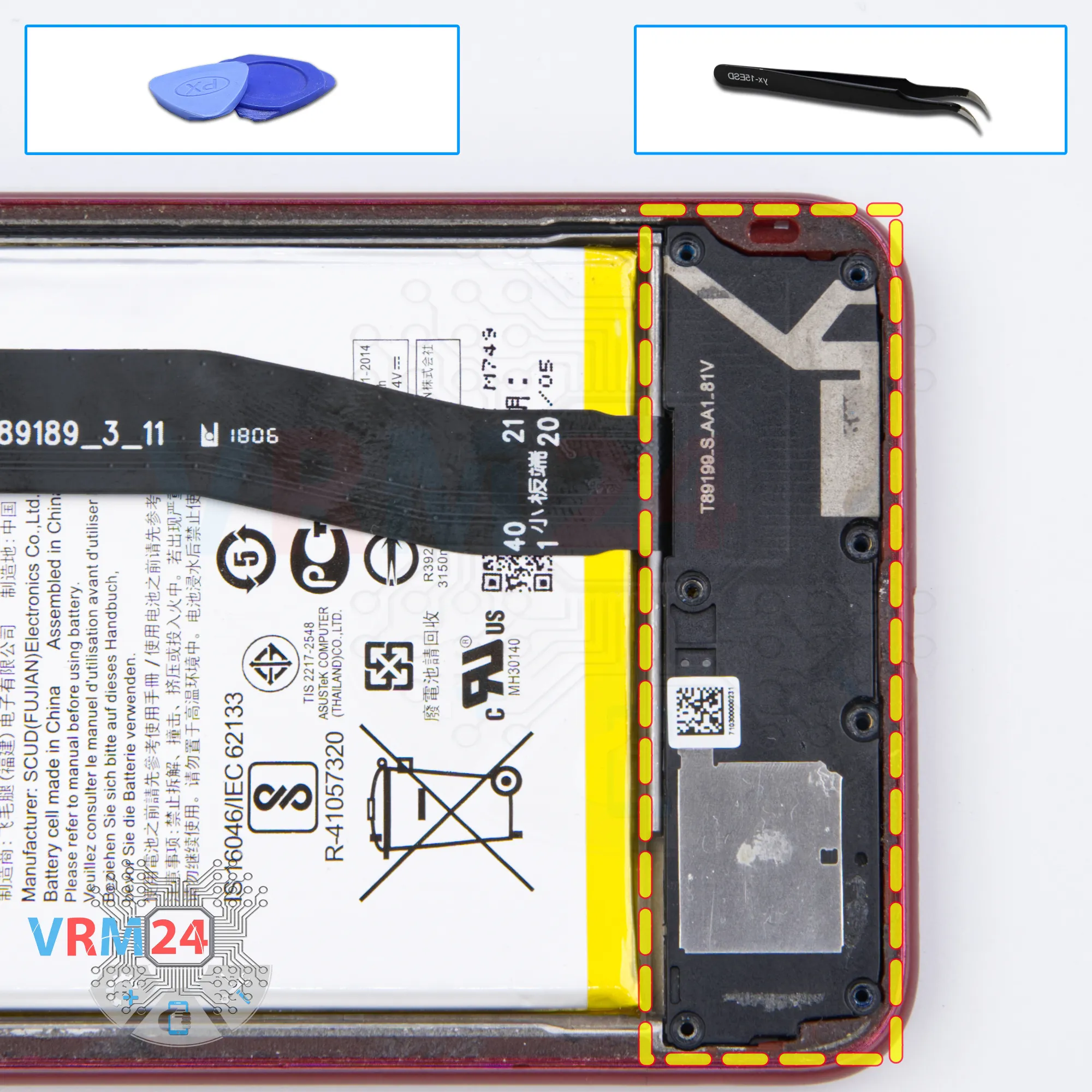
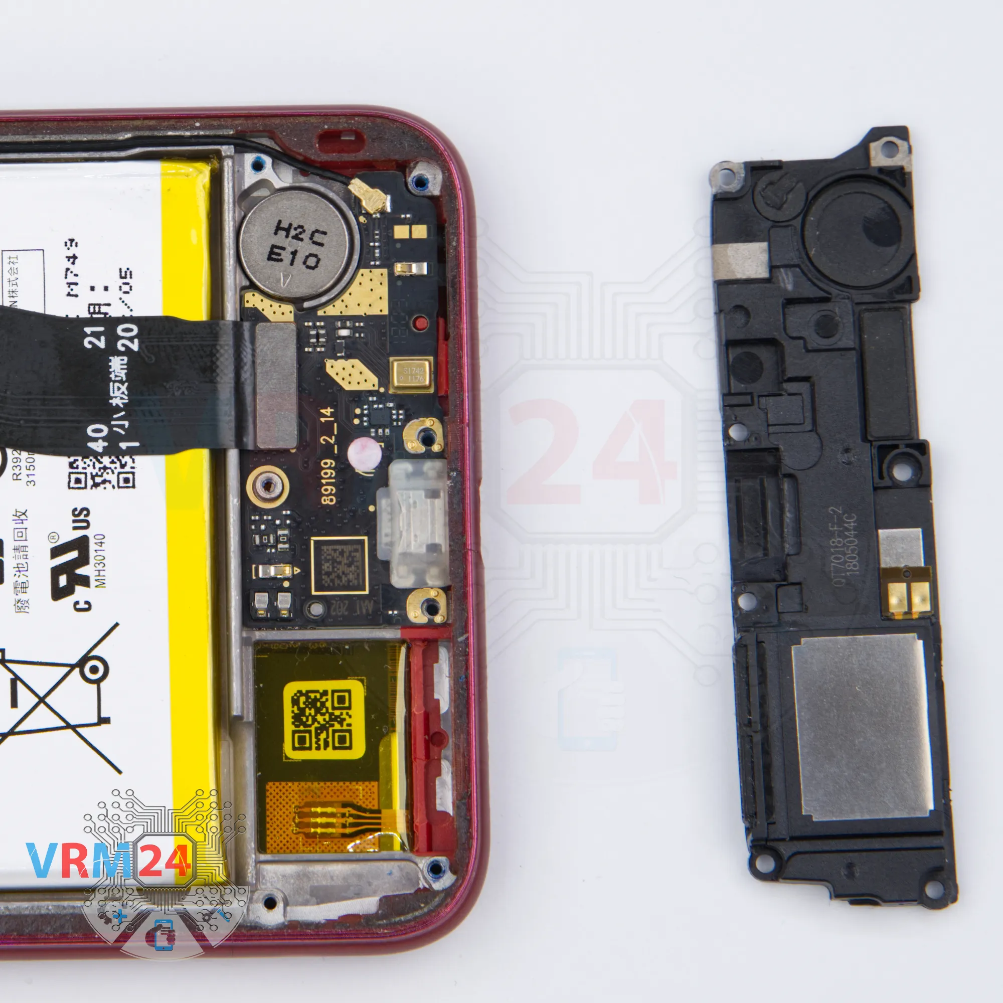
Step 16. Remove the loudspeaker
Pry over the edge and remove the loudspeaker assembly with antenna tracks.
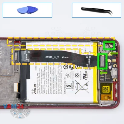
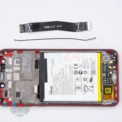
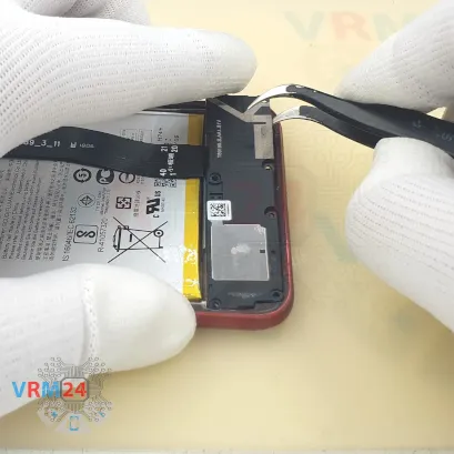
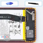
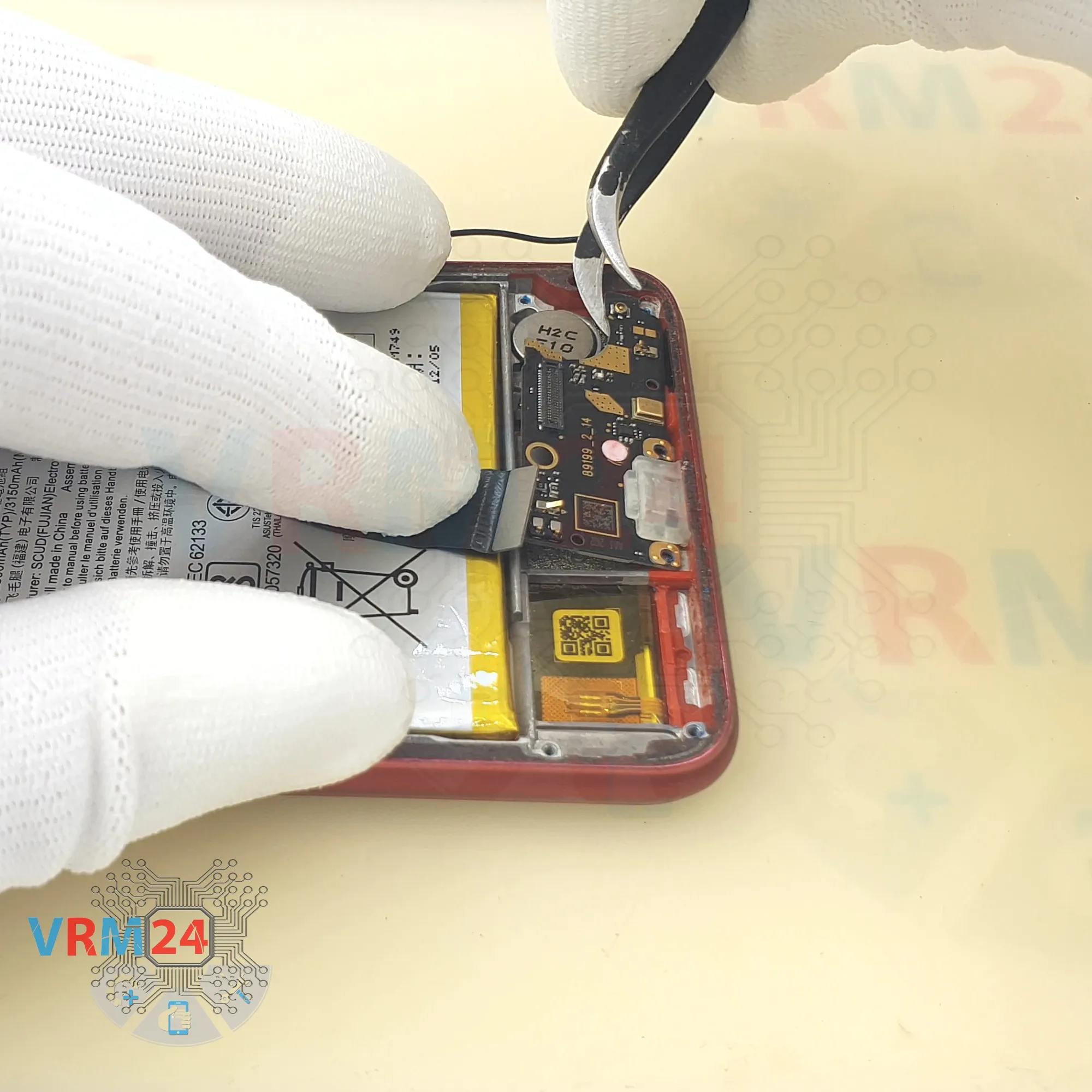
Step 17. Remove the interconnect cable
Carefully, preferably from the edge, disconnect the connectors and remove the inter-board cable and coaxial cable.


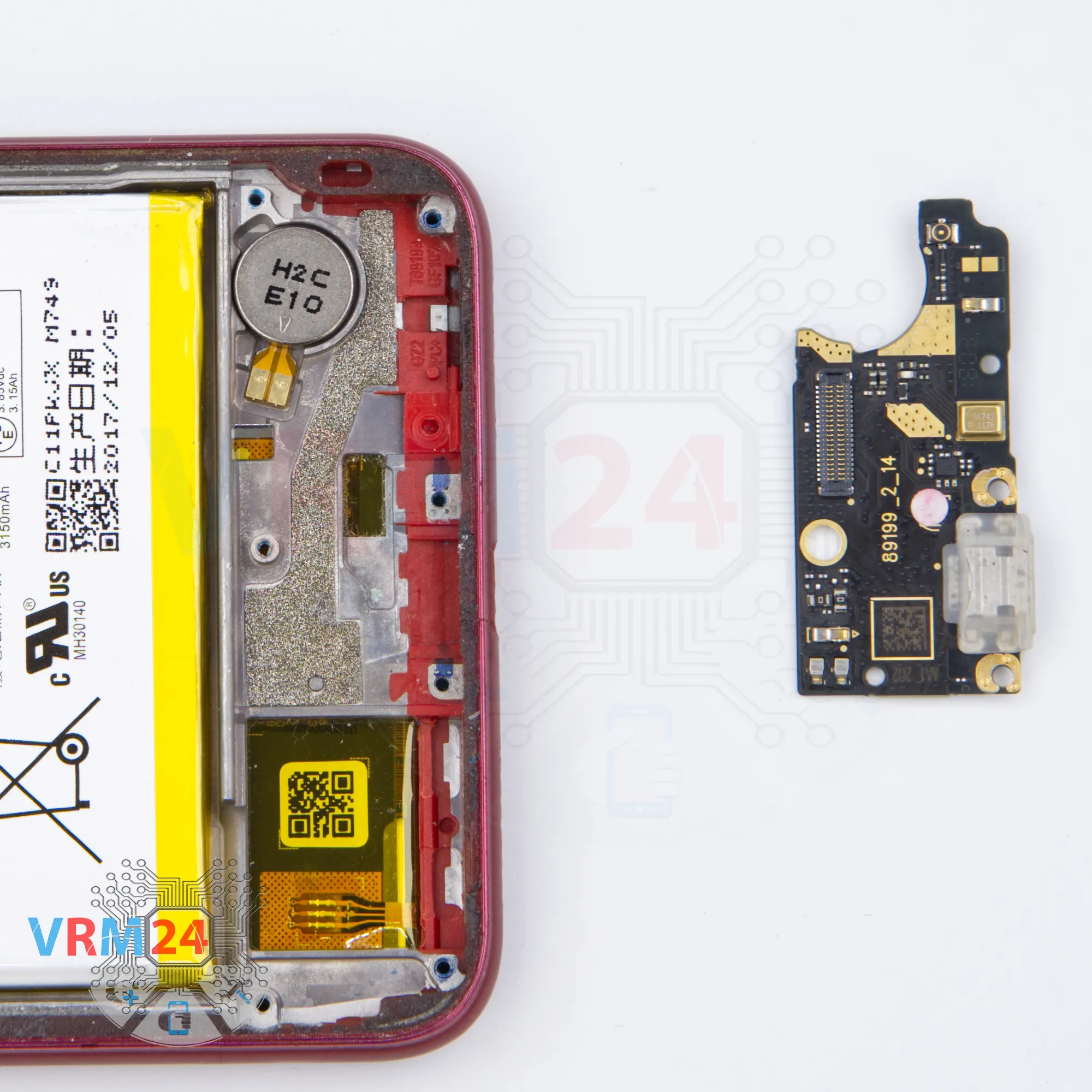
Step 18. Remove the sub-board
Remove the sub-board. It may be glued to the frame or attached with attachments like latches or hooks, so be careful.
ℹ️️ The sub-board contains a charging port (Micro-USB), microphone, spring contacts for the speaker, vibration motor, and an antenna unit.
⚠️️ It is not necessary to insert the tool underneath when removing the sub-board. Internal components could be damaged.
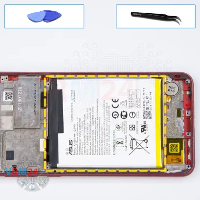

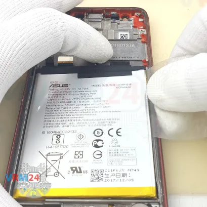


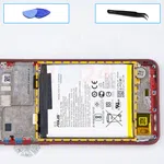
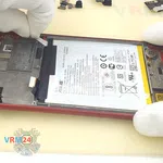

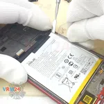
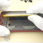
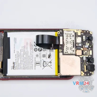
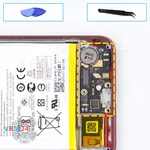
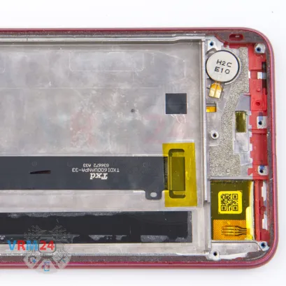
Step 19. Remove the battery
With extreme care, remove the battery because it is glued from the inside by the manufacturer.
Also, we need to remember or look in advance at the location of the flat cables under the battery, so as not to damage them.

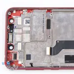


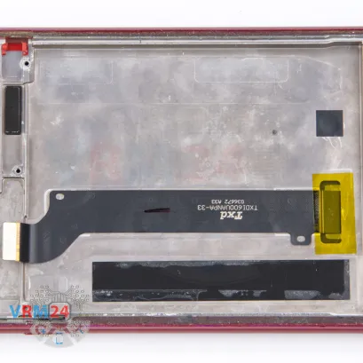
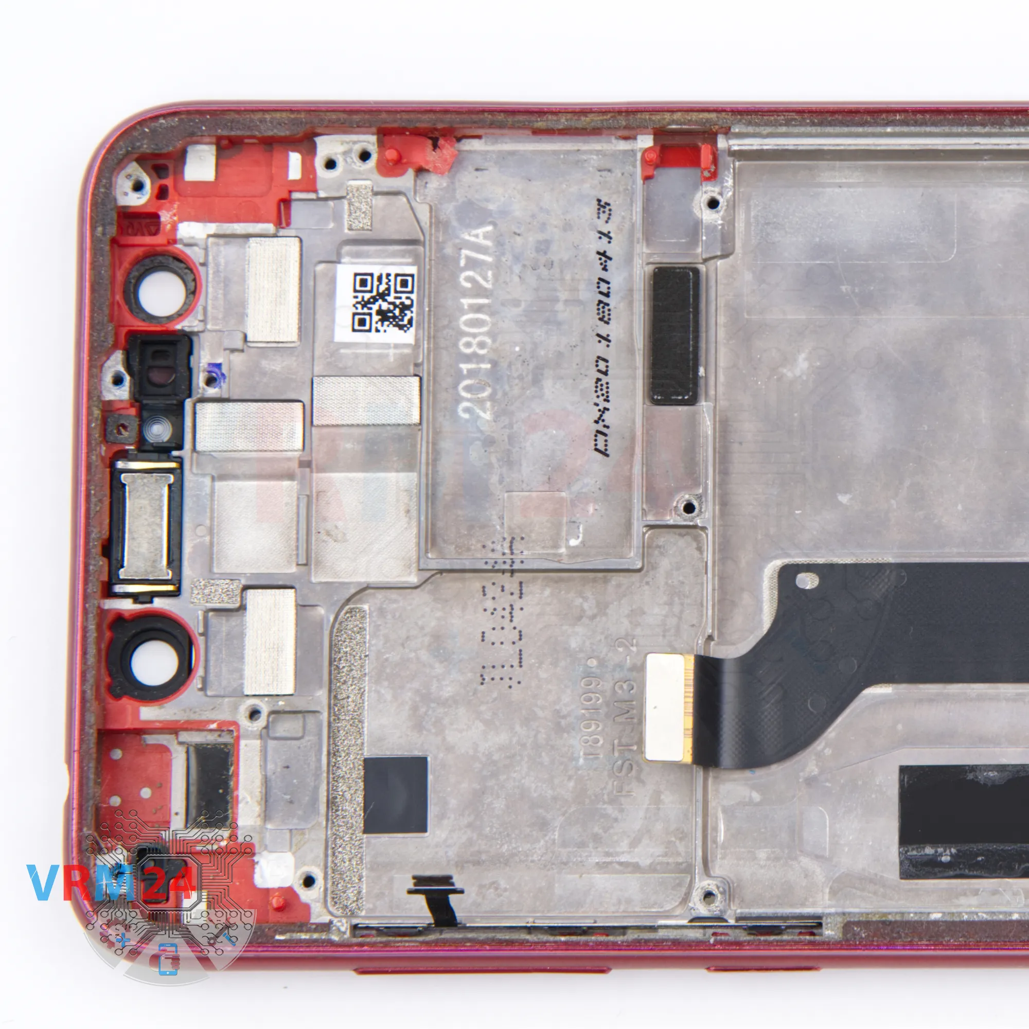
Step 20. In the display frame remained
In the display frame remained: the earpiece speaker, vibration motor.
Detailed disassembly instructions of Asus ZenFone 5 Lite ZC600KL in the video, made by our mobile repair & service center:
If you have a question, ask us, and we will try to answer in as much detail as possible. If this article was helpful for you, please rate it.

Disassembling\Repair has medium complexity and takes about minutes in time.
Our manual is suitable for all models Asus ZenFone 5 Lite ZC600KL — Asus ZenFone 5Q released for markets in different countries.
Back to the list