

⚠️️ Before disassembling, do not forget to turn your phone off.
Teardown difficulty:
Moderate
Moderate
Recommended tools


Disassembly/Repair of the mobile device HONOR 200 (HONOR 200 ELI-NX9) with each step description and the required set of tools.

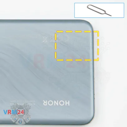

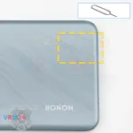
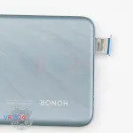

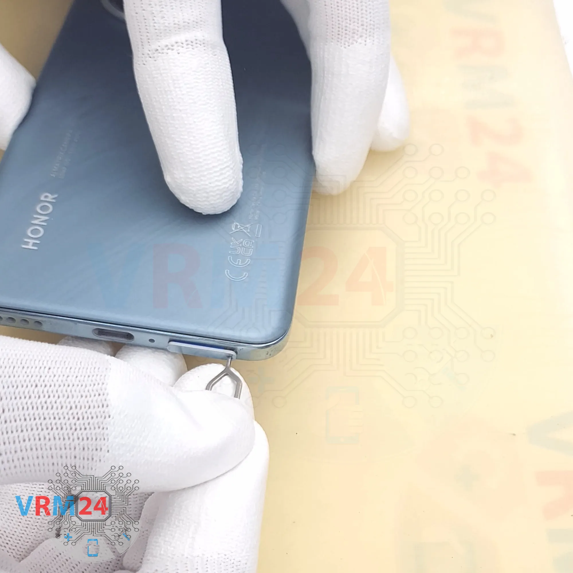
Step 2. Remove the tray
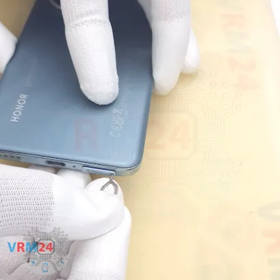
First, we need to remove the SIM tray. To do this, we use a special tool.
Carefully insert it into the hole and push the tray out.
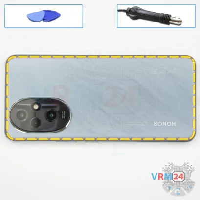


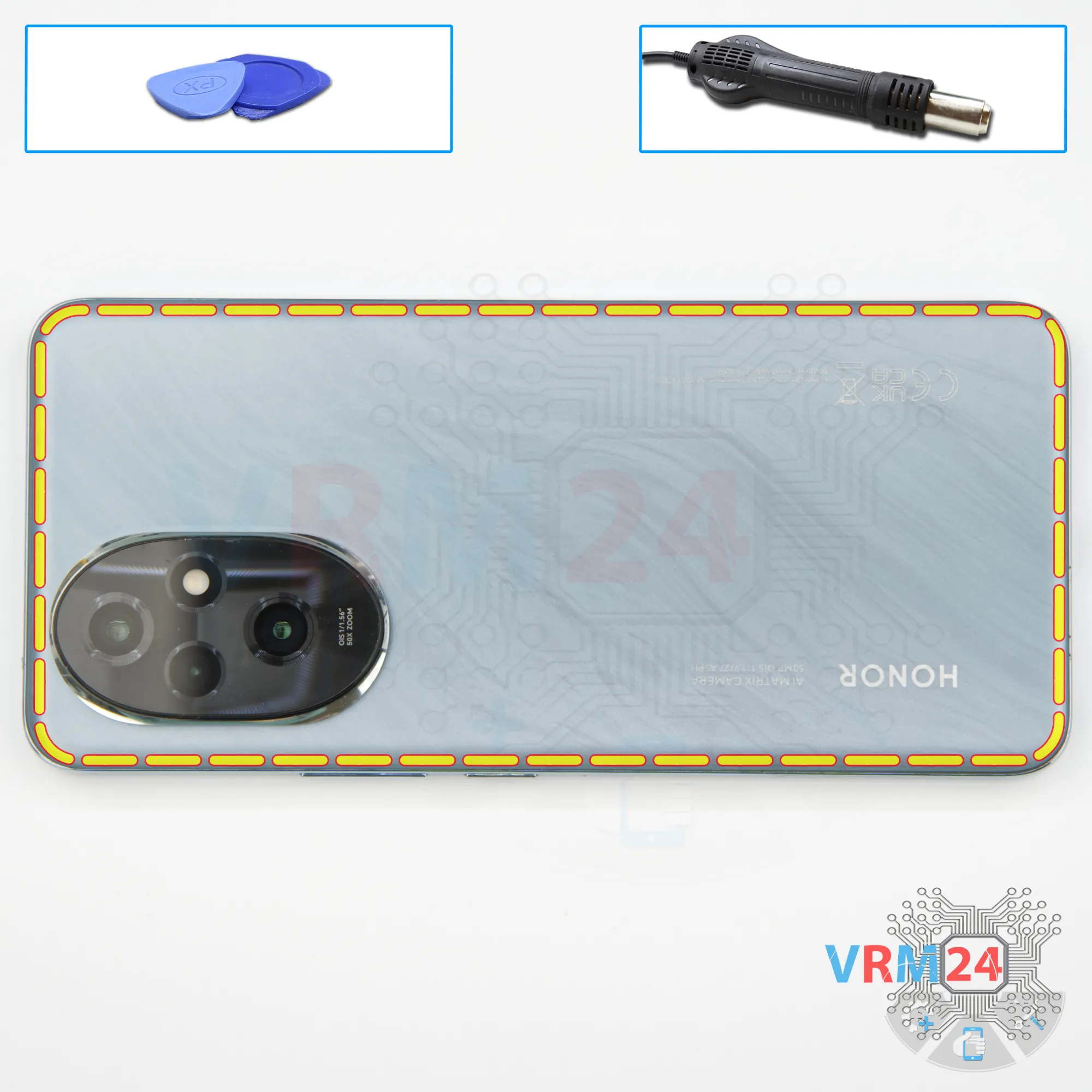
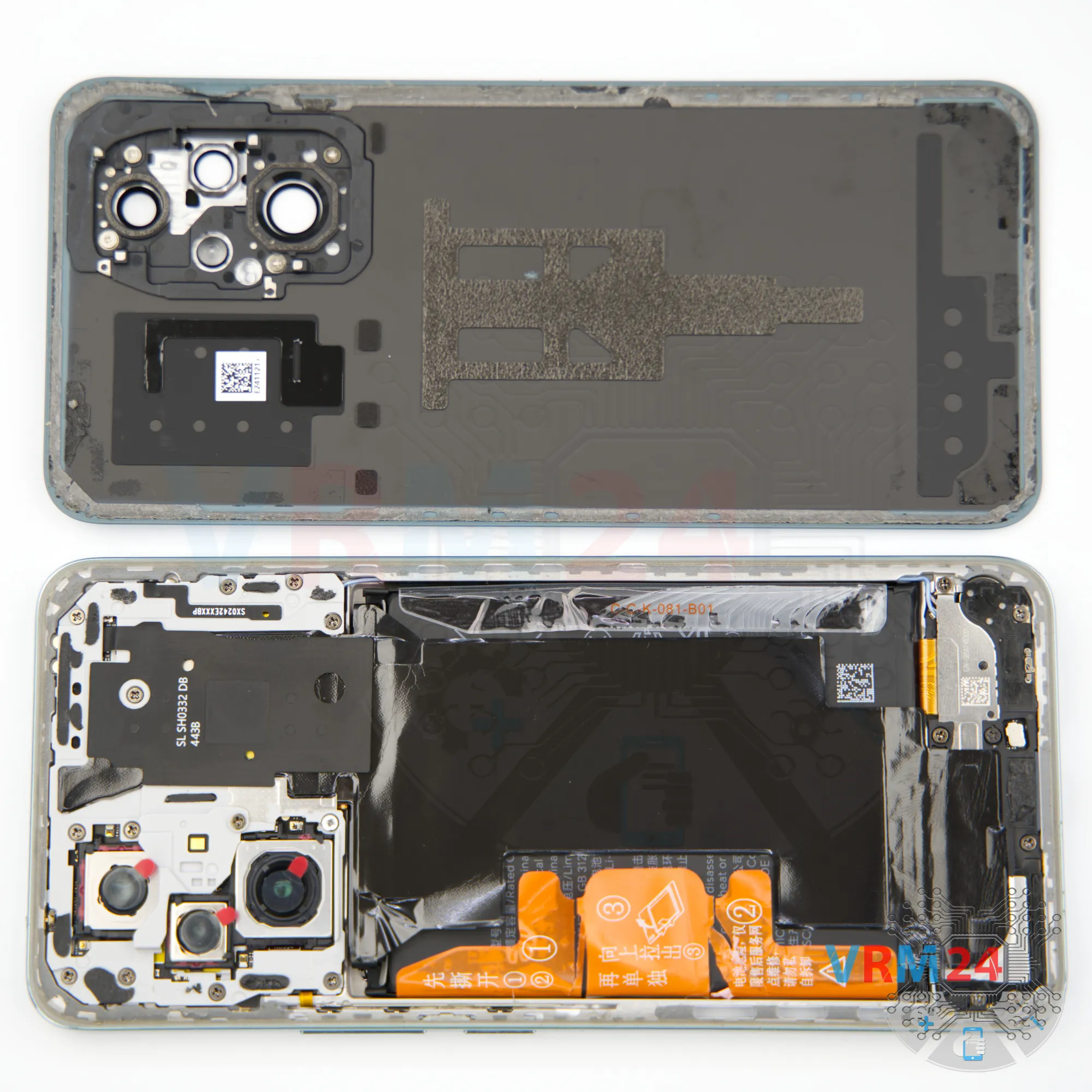
Step 3. Open the back cover
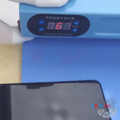
Next, we need to heat the back cover surface to about 70°C (160°F). For this, we’re using a heating pad, but you can also use a hairdryer.
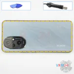
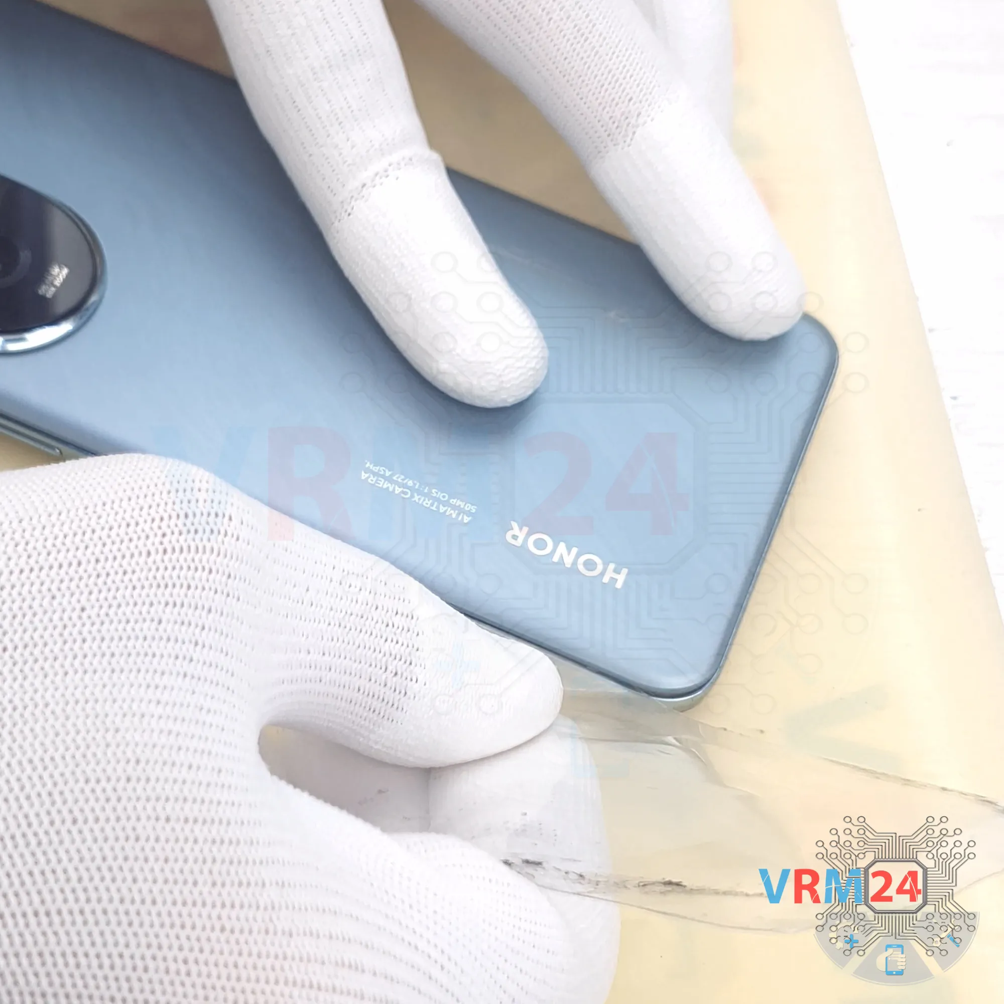
After about 10 minutes, we can start removing the back cover. To do this, we use a thin plastic film. Gently insert it into the gap between the back cover and the mid-frame, then slide it along the edge to cut through the adhesive.
As always, be extra careful around the camera area so you don’t damage the lenses.
Also, don’t push the film in too deep since we don’t know exactly what’s under the cover.
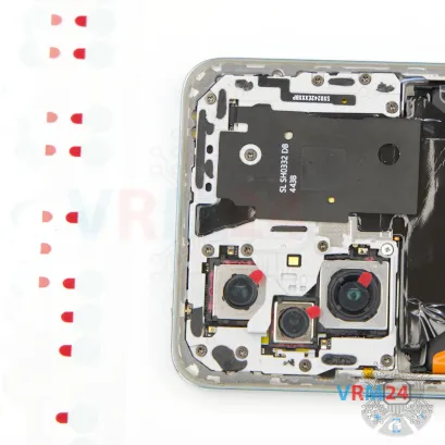

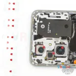
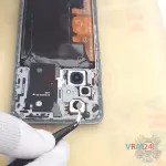
Step 4. Protecting camera lenses
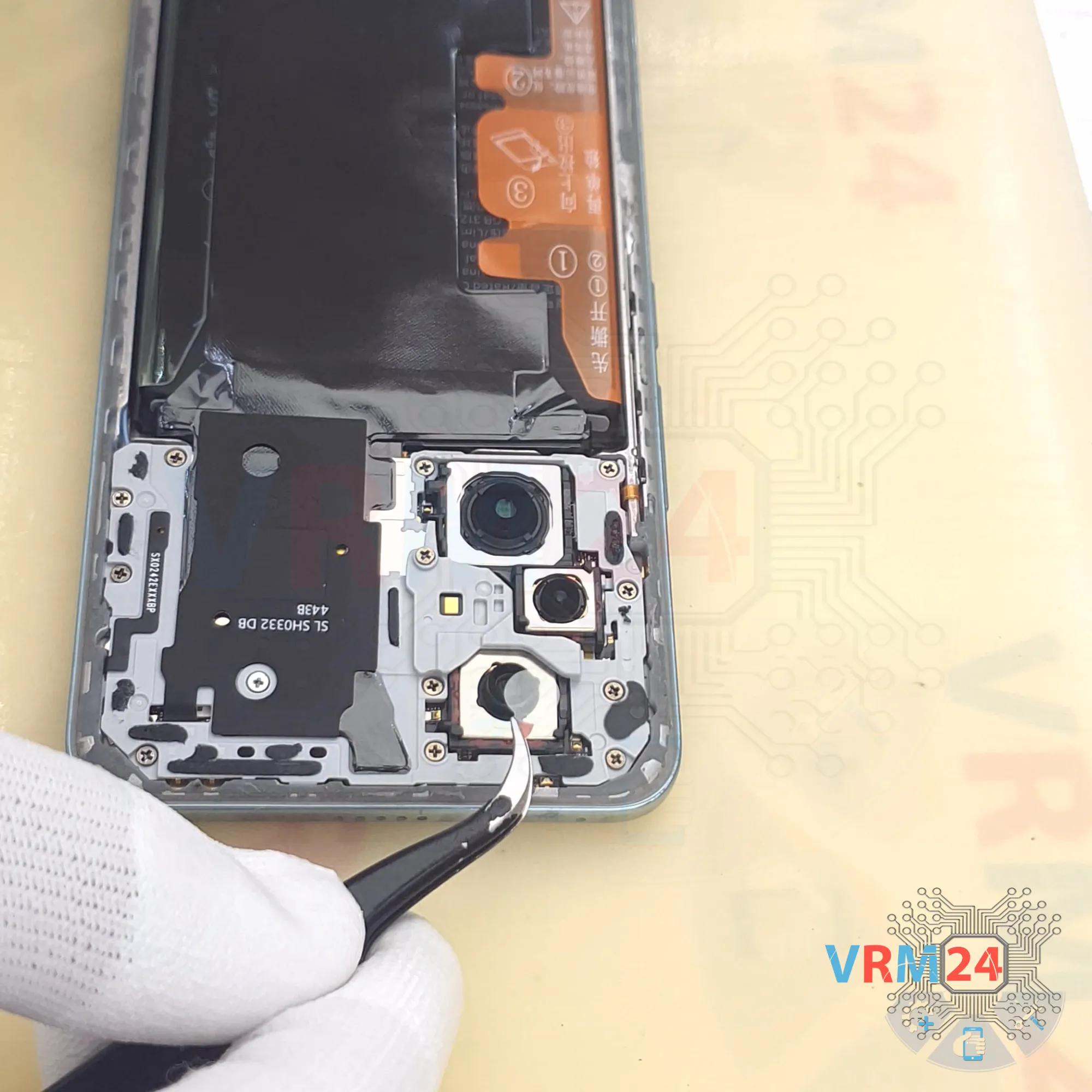
Before unscrewing the screws, we can cover the camera lenses. For this, we use a protective film.
Note: we’re sticking the film not directly onto the lenses, but onto the rim around the cameras.
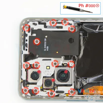
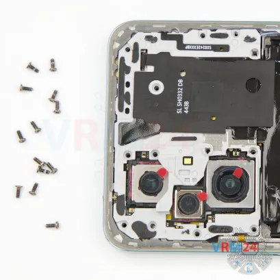


Step 5. Unscrew the screws
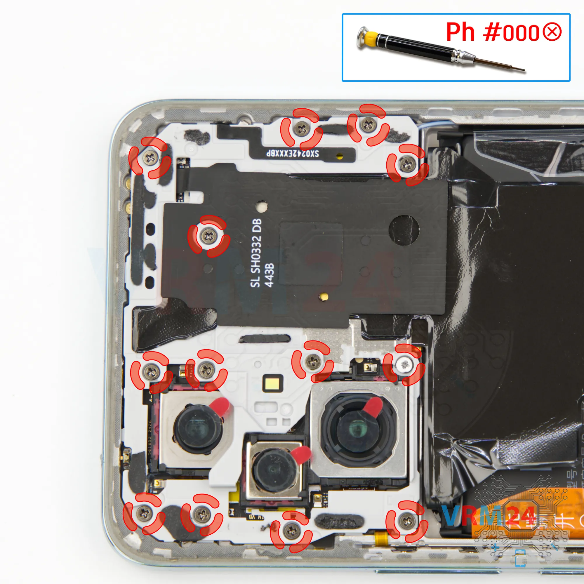
Now let’s move on to removing the screws. For this, we use a 1.5 mm Phillips screwdriver, or a Philips #000.
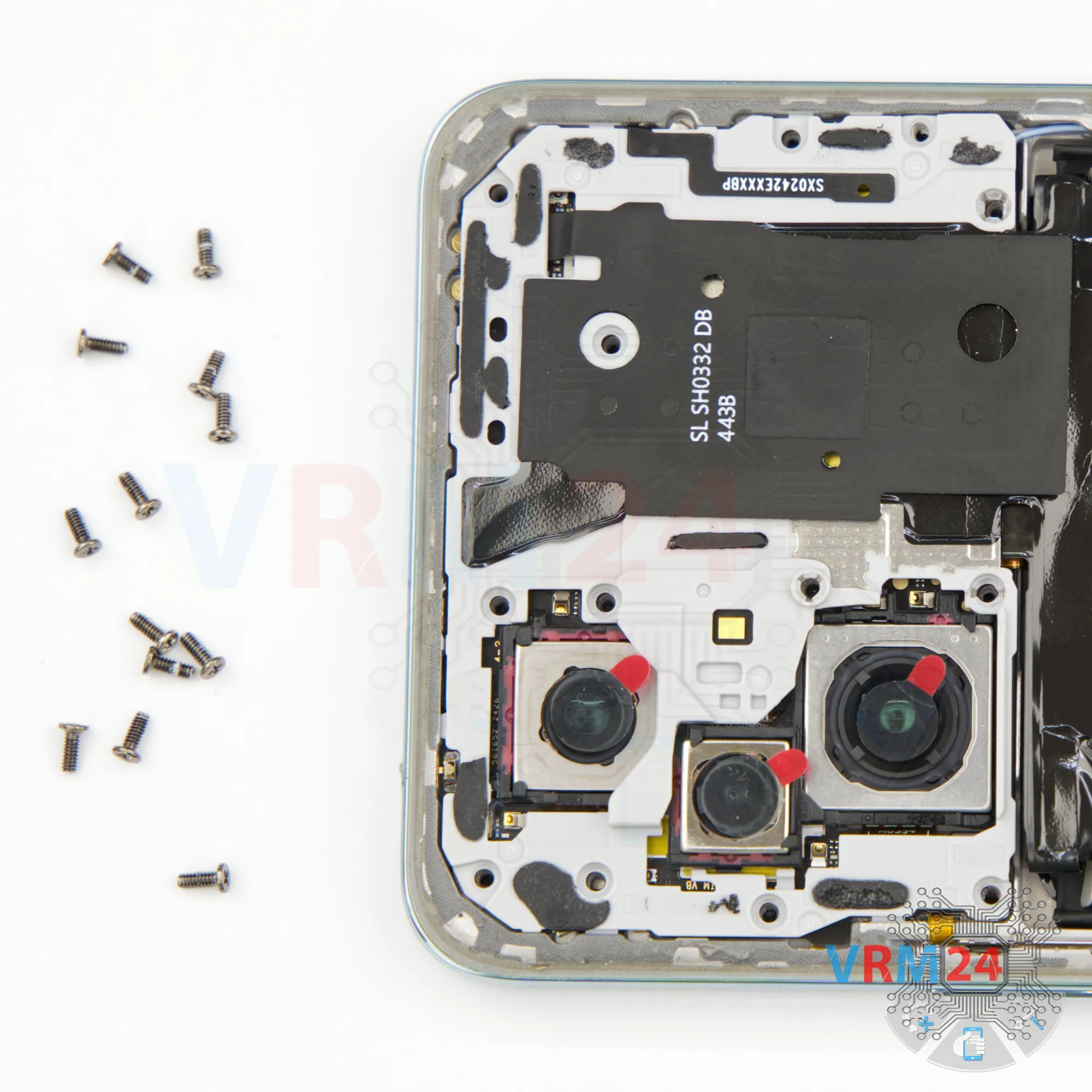
Carefully unscrew the screws.
On this HONOR series, the screws are hard to take out since they’re completely non-magnetic. That’s why we’ll need tweezers to remove them safely.

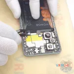
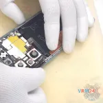
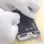
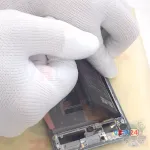
Step 6. Open the cover
Next, we remove the top cover using a non-metallic tool.
Carefully lift it, flip it over.
On the cover, we can see contact pads.

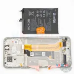
Step 7. Disconnect the battery connector
Then, using a non-metallic tool, we disconnect the battery connectors.
ℹ️️ The HONOR 200 ELI-NX9 model has a battery HB4965590EIW with a capacity of 5200 mAh (also known as a rechargeable battery).
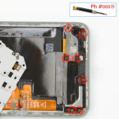
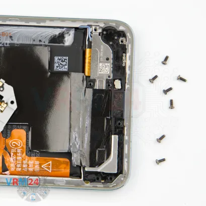
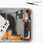
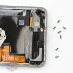
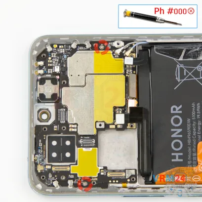
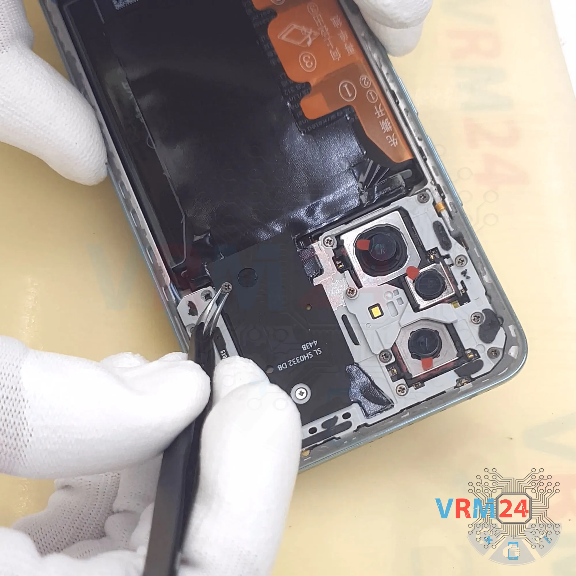
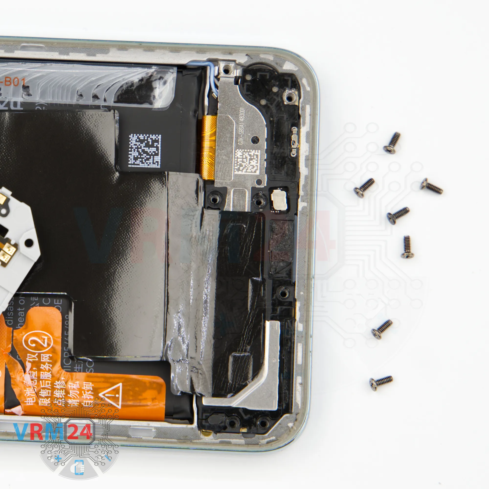
Step 8. Unscrew the screws
Now, let’s unscrew the screws at the bottom using the same 1.5 mm Phillips screwdriver.
These screws may differ, and they’re also not magnetic, so we need to carefully use tweezers to remove them and place them on a special pad.

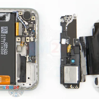


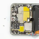
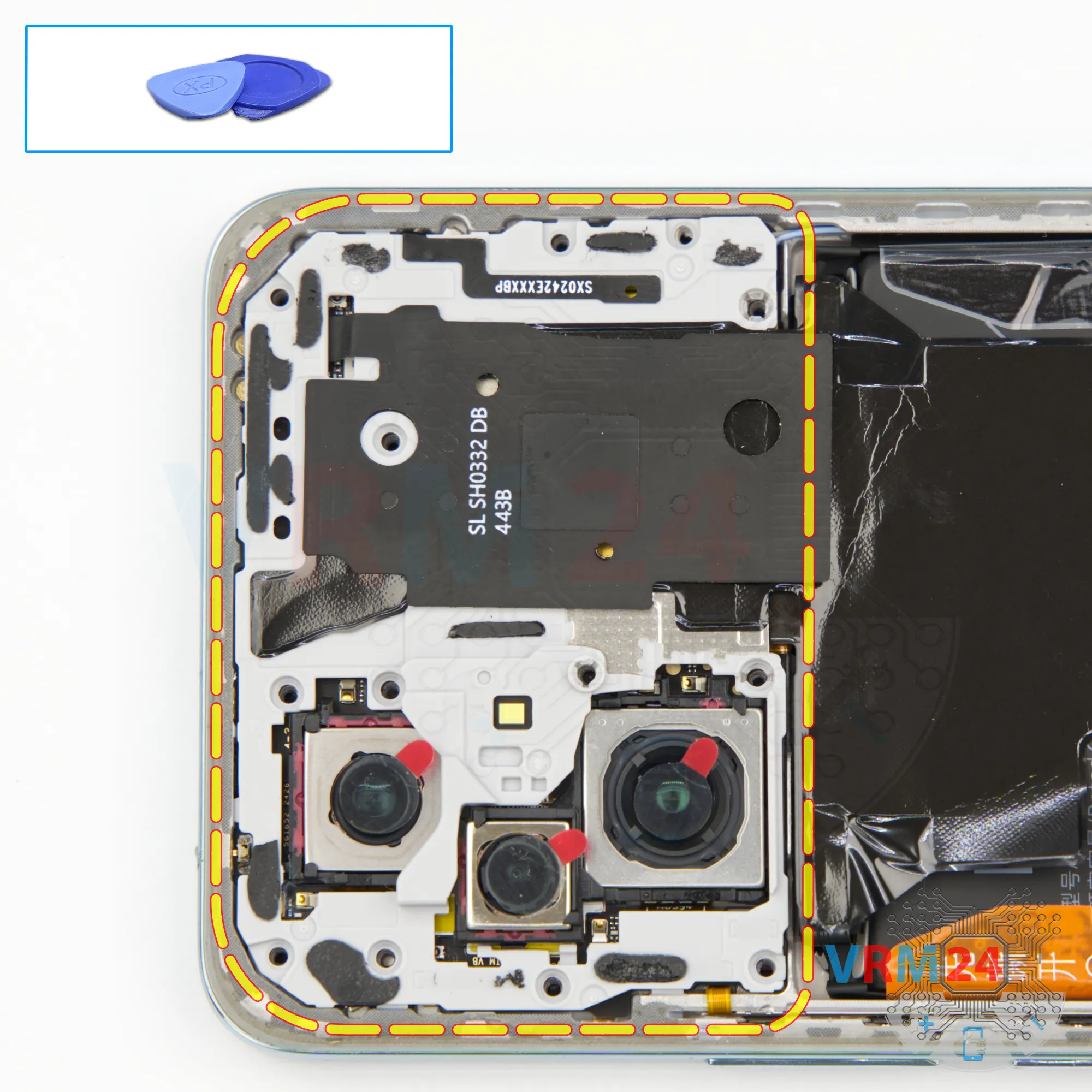
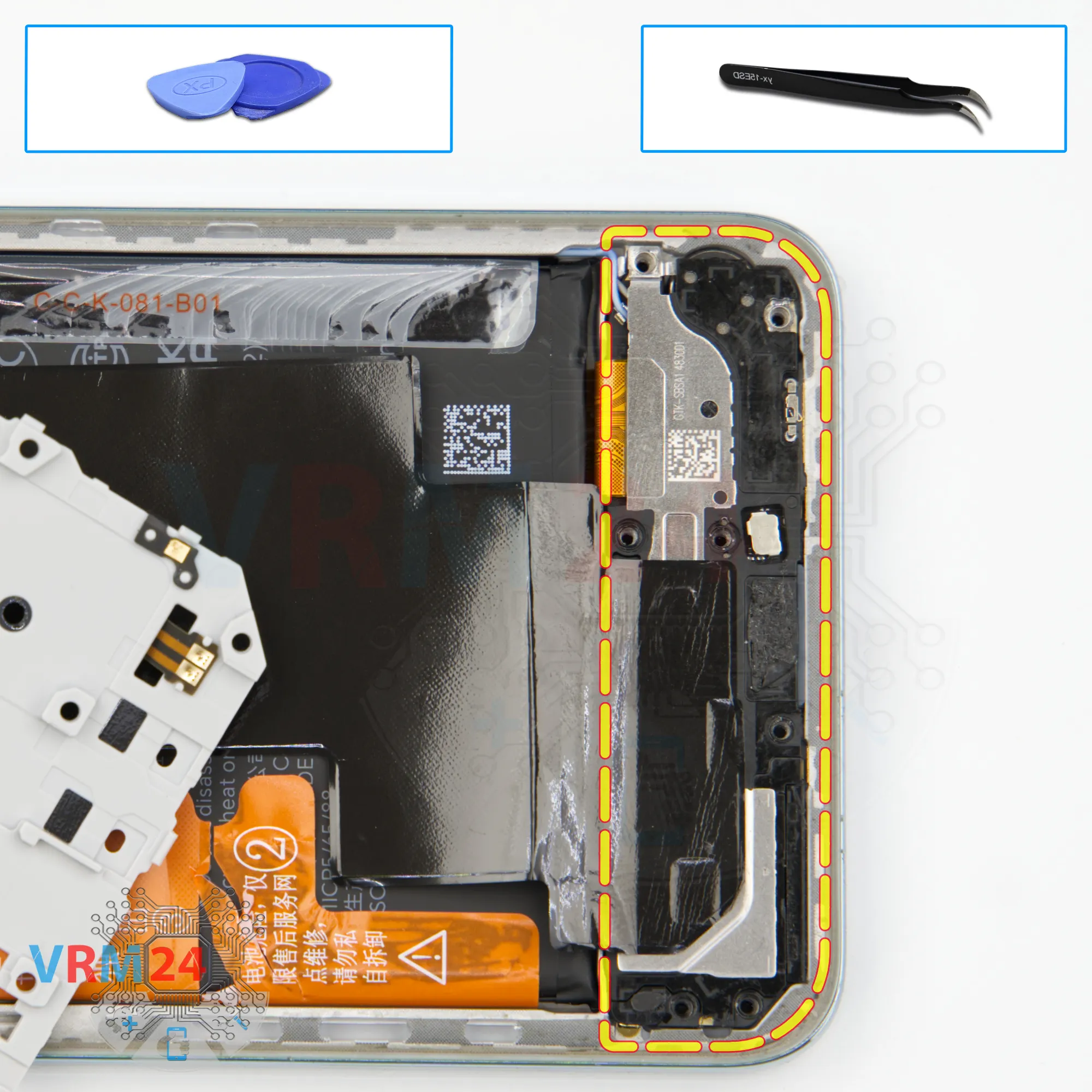
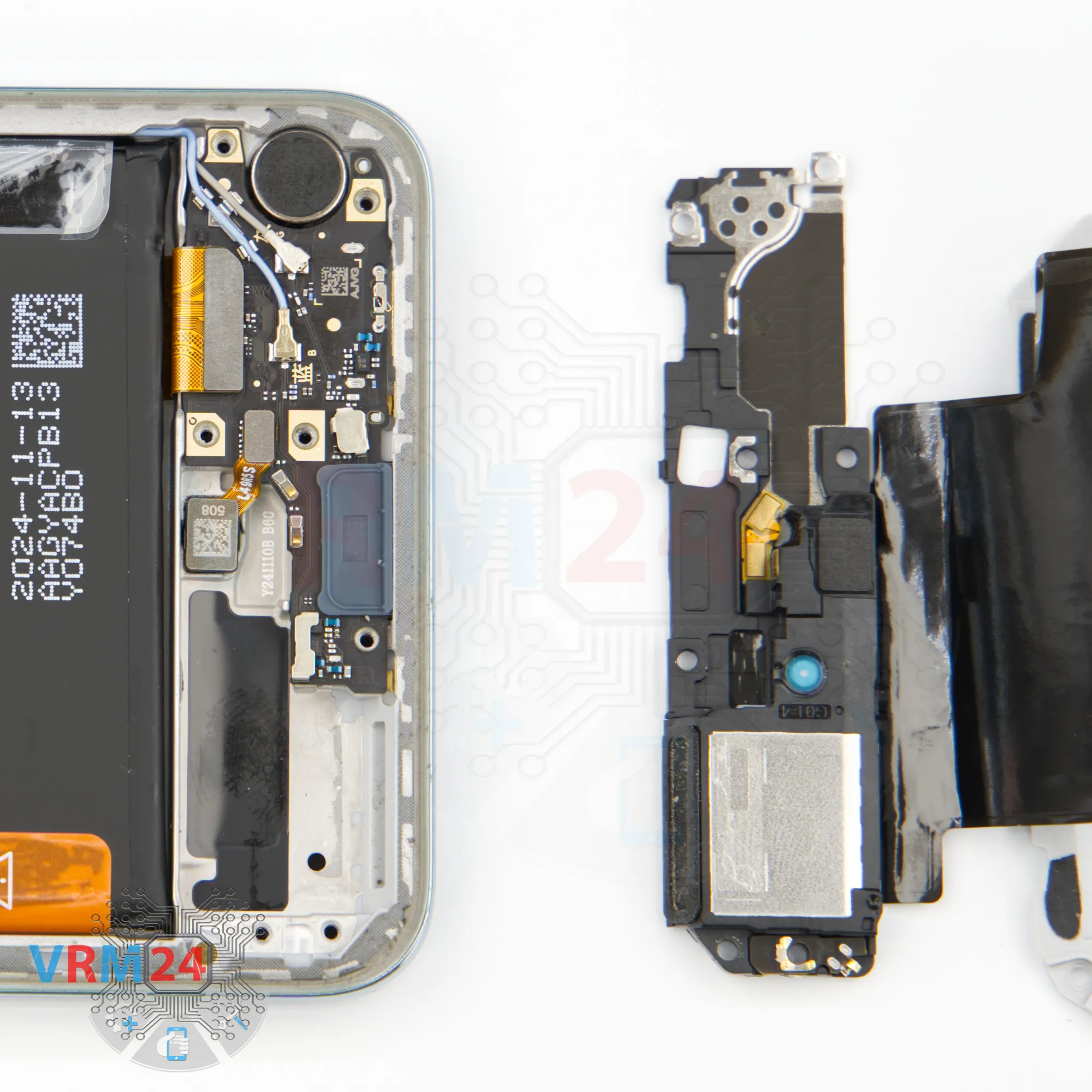
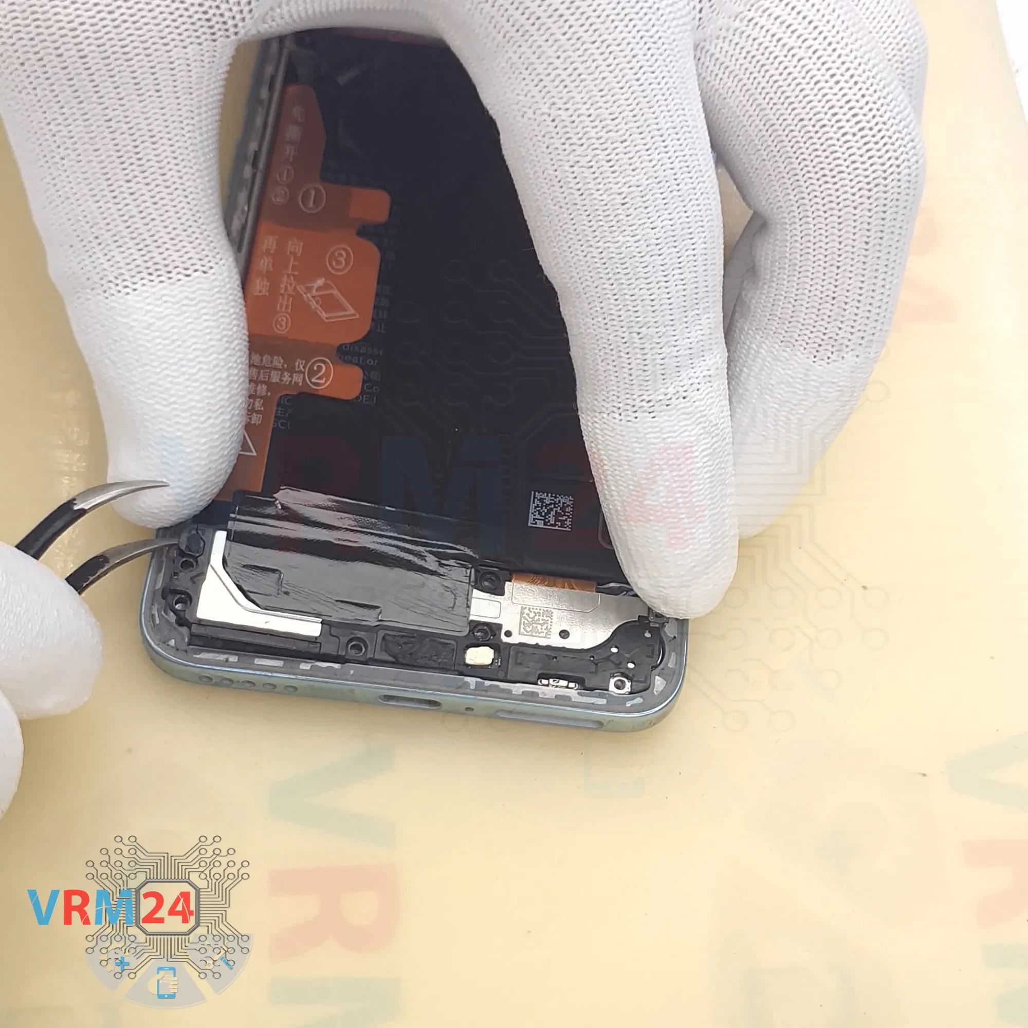
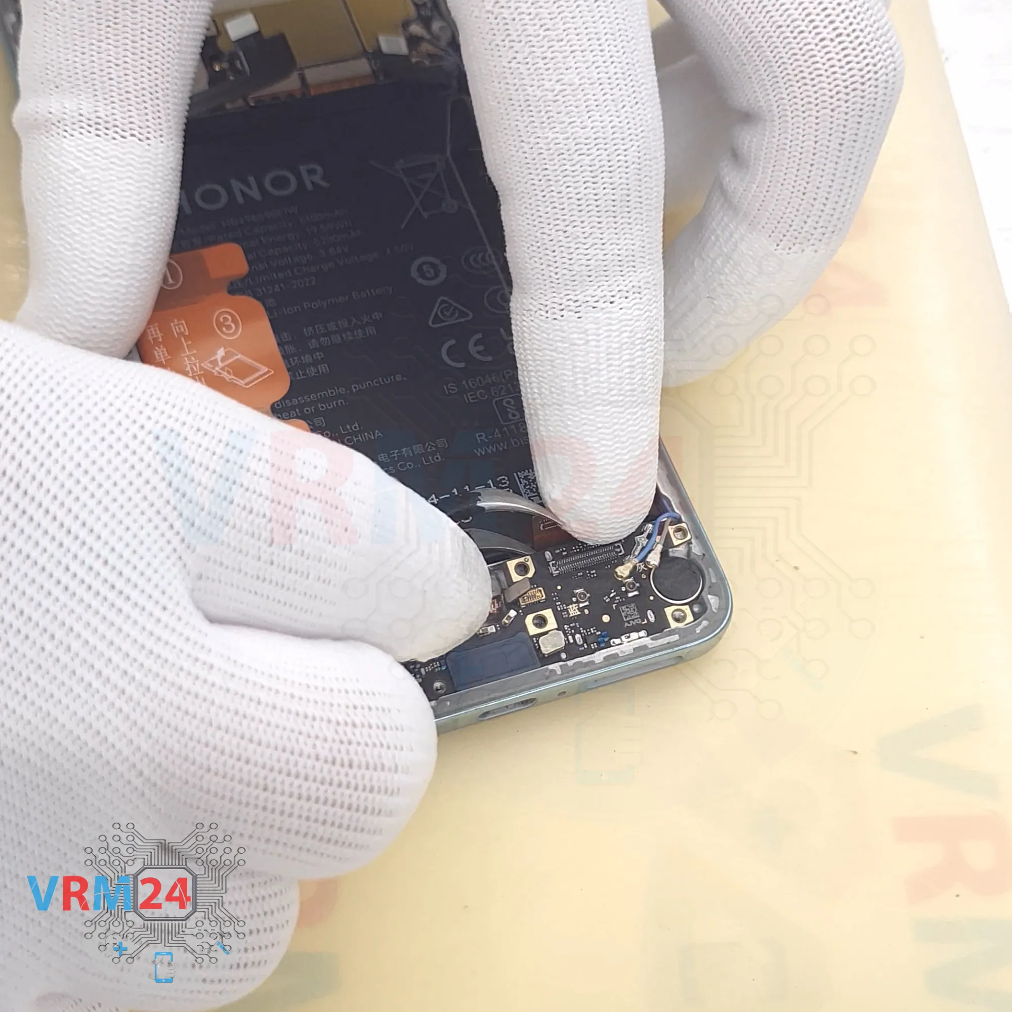
Step 9. Remove the loudspeaker
After that, we gently try to remove the cover with the loudspeaker. As always, you need to find the right spot to pry it up, and then the cover comes off easily.

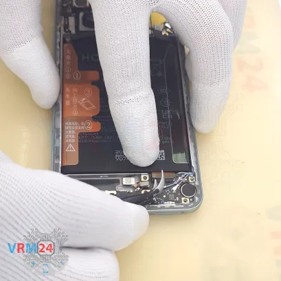
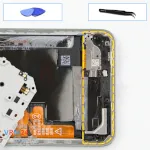
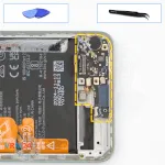
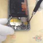
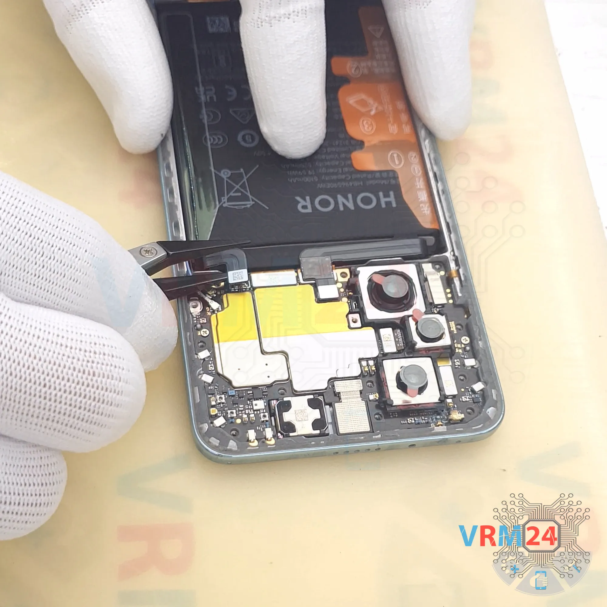
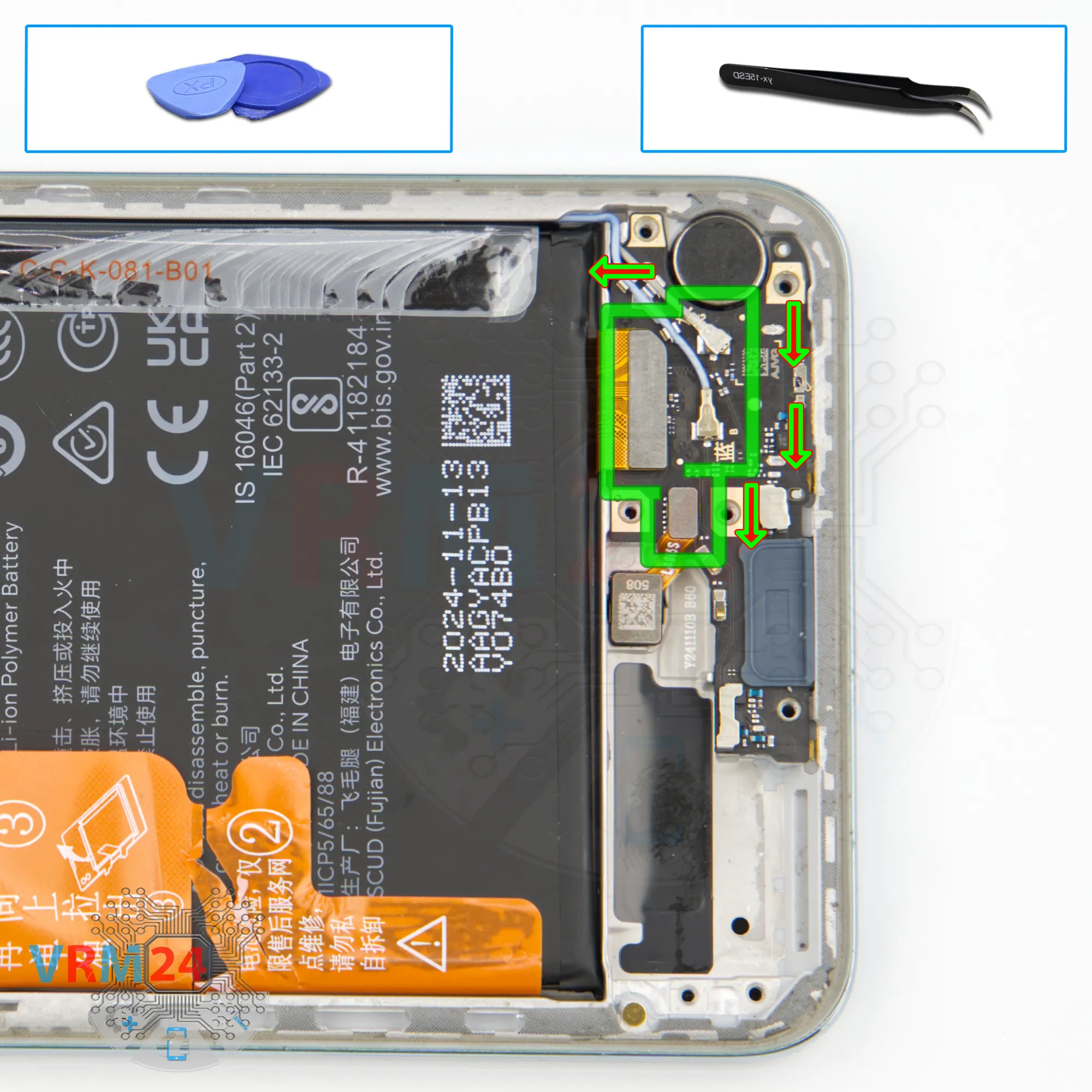
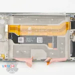
Step 10. Disconnect the connectors
Next, we can disconnect the connectors in the bottom part.
First, we disconnect the fingerprint sensor connector, the inter-board cable connector, then the two coaxial cable connectors.
We also release the cables from their clamps on the sub-board and fold them back a little.


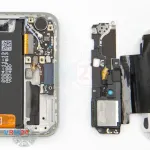
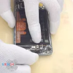
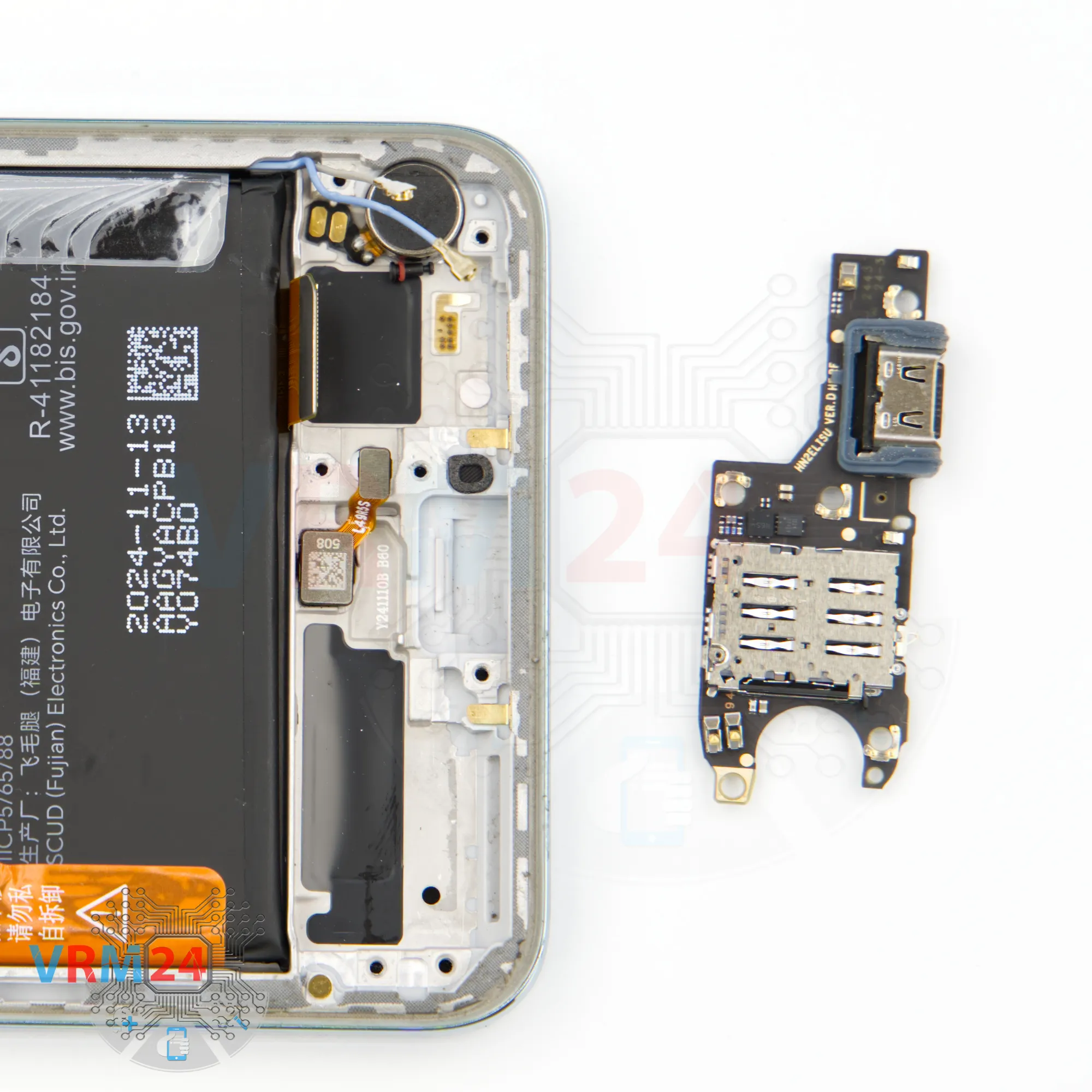
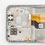
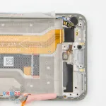
Step 11. Remove the sub-board
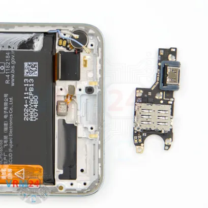
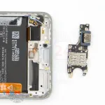
Now we can carefully remove the sub-board. Make sure nothing is in the way, gently lift it, and take it out.
On the sub-board, we have the charging port, the microphone under the shield, and the card connector.
In the display frame, we’re left with the fingerprint sensor and the vibration motor.


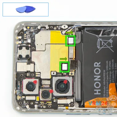
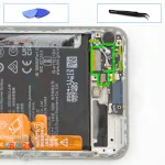
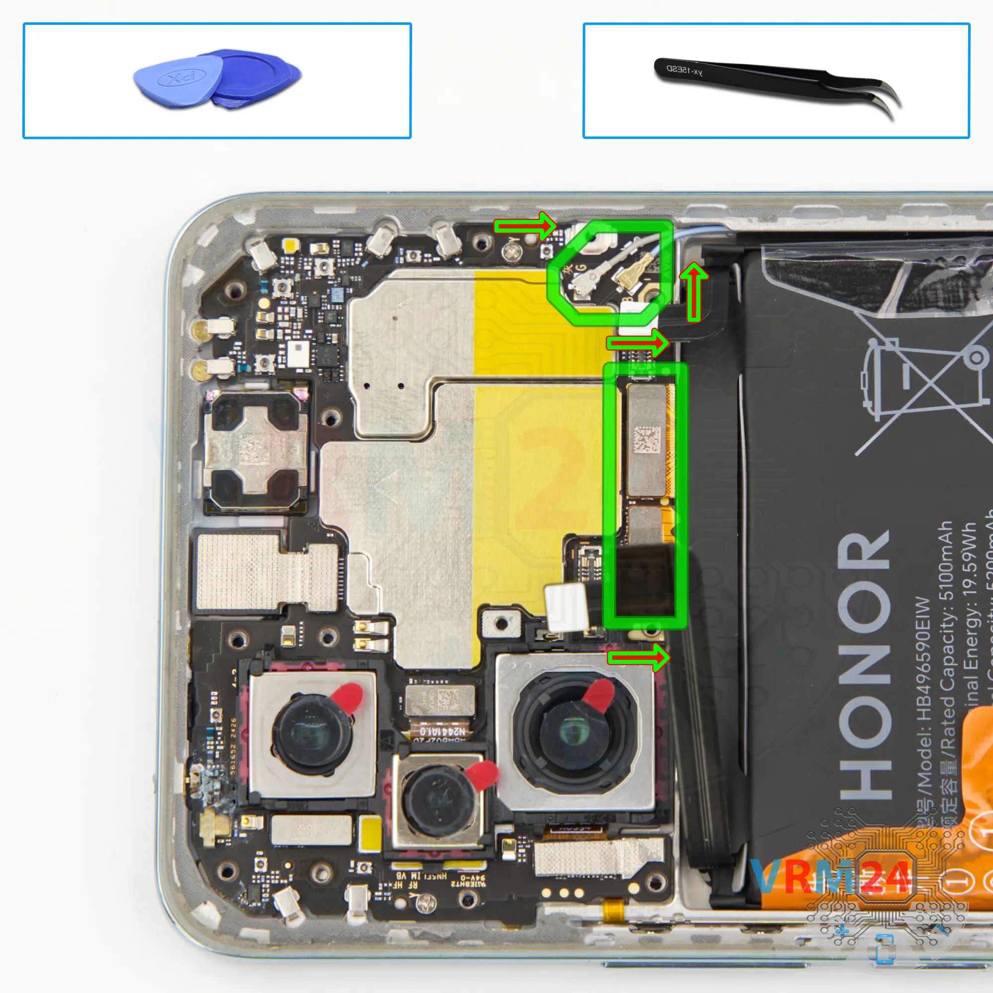
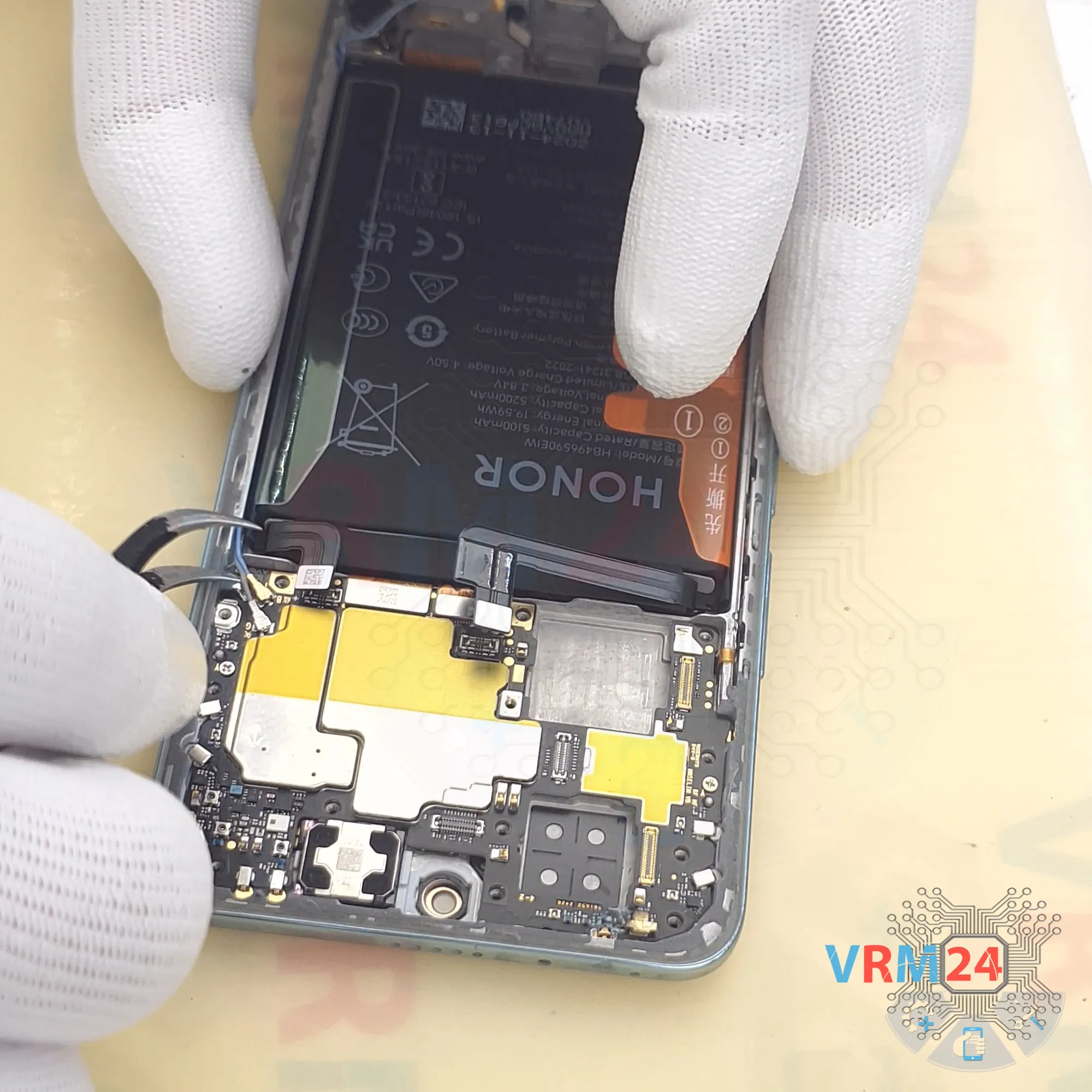
Step 12. Disconnect the connectors
Now let’s move on to the motherboard.
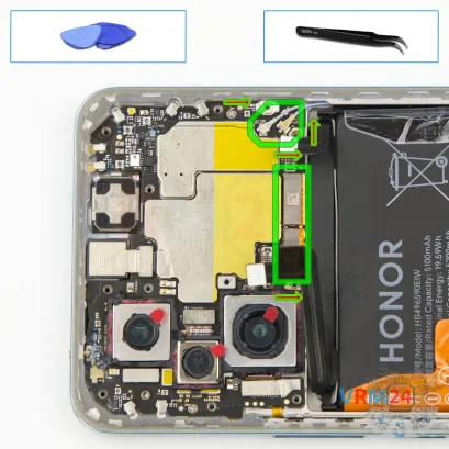
We disconnect two connectors from the two coaxial cables. Then we disconnect the inter-board cable connector and the display cable connector.


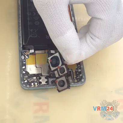

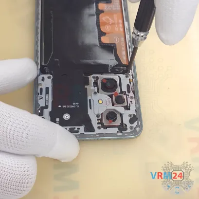
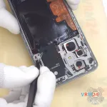
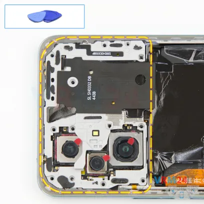
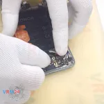
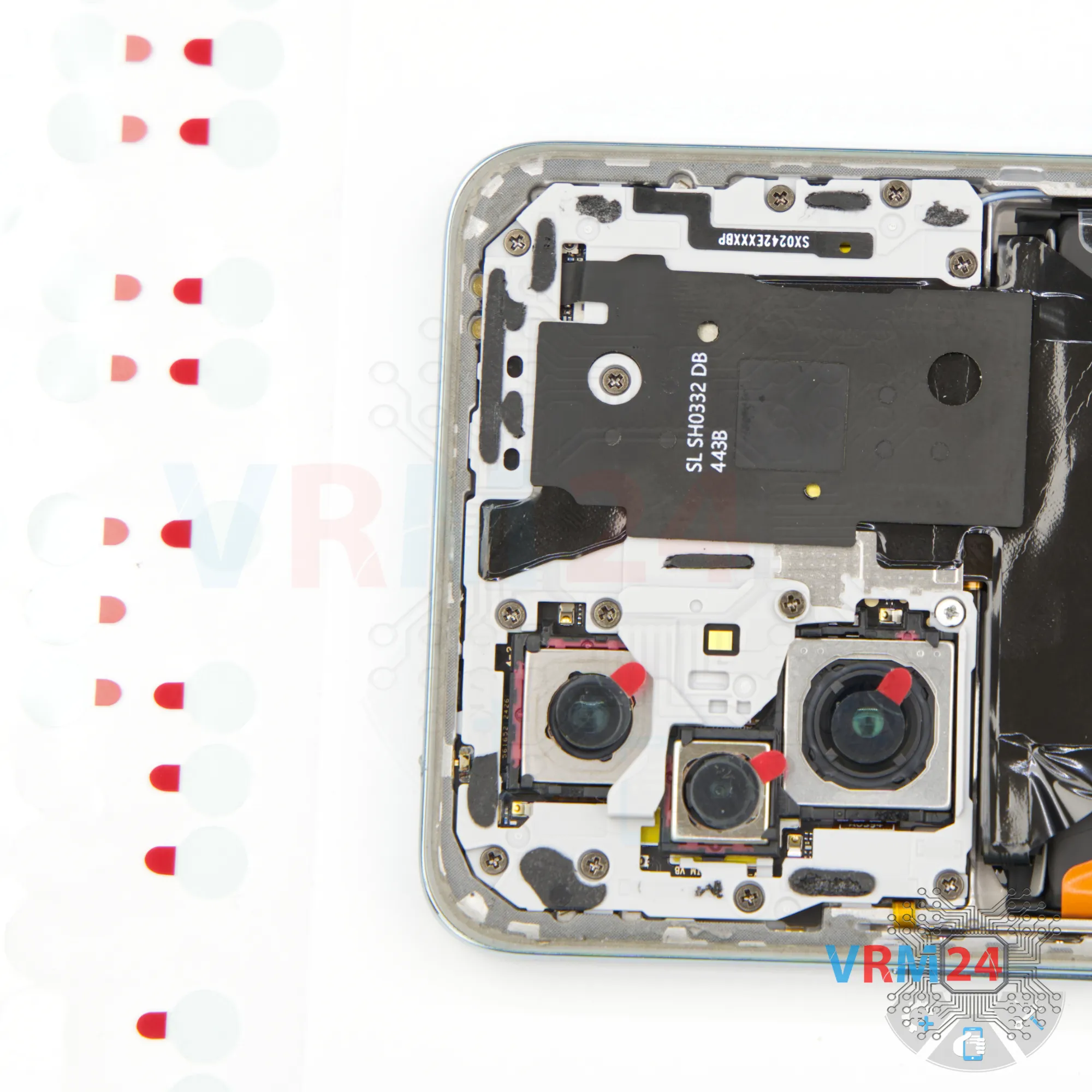
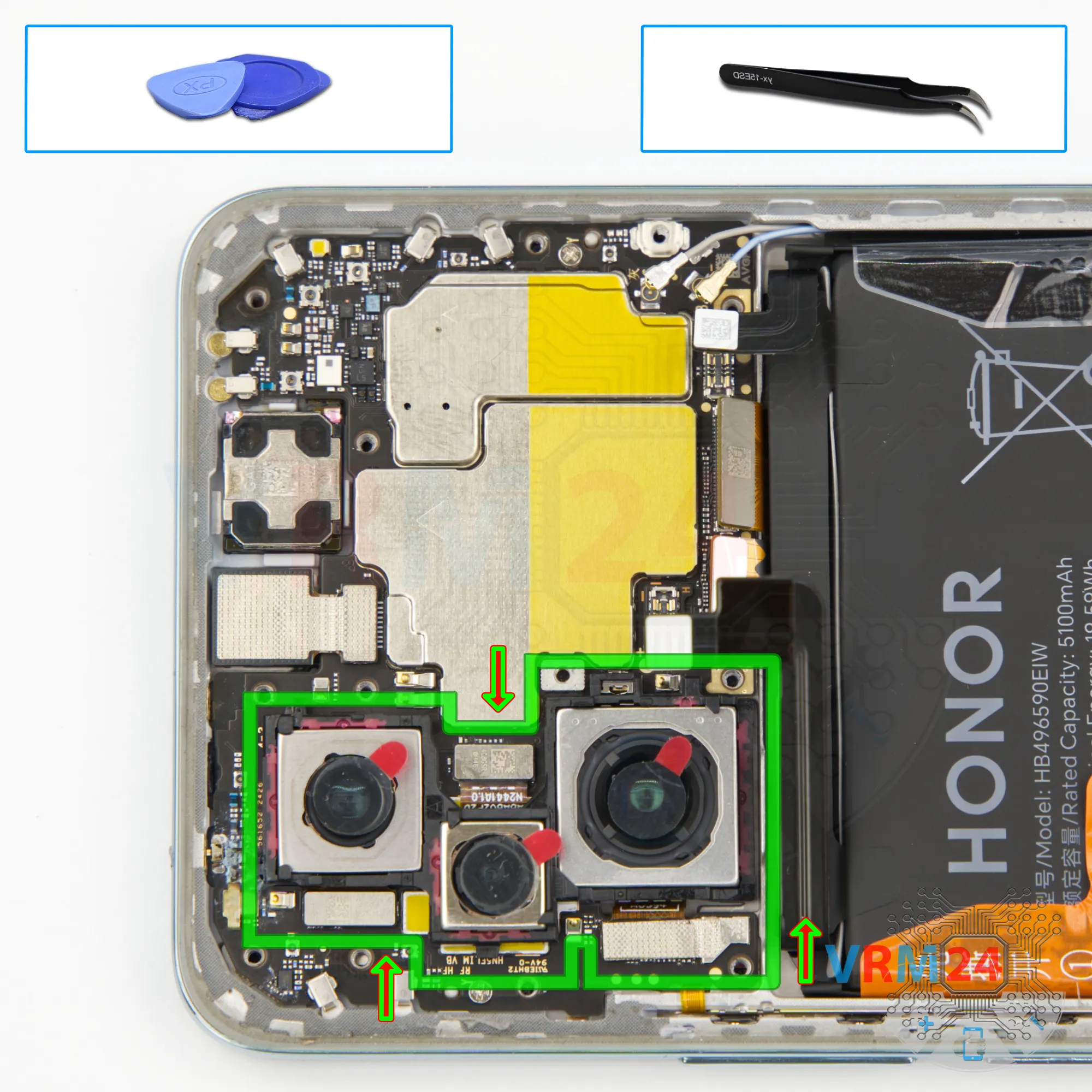
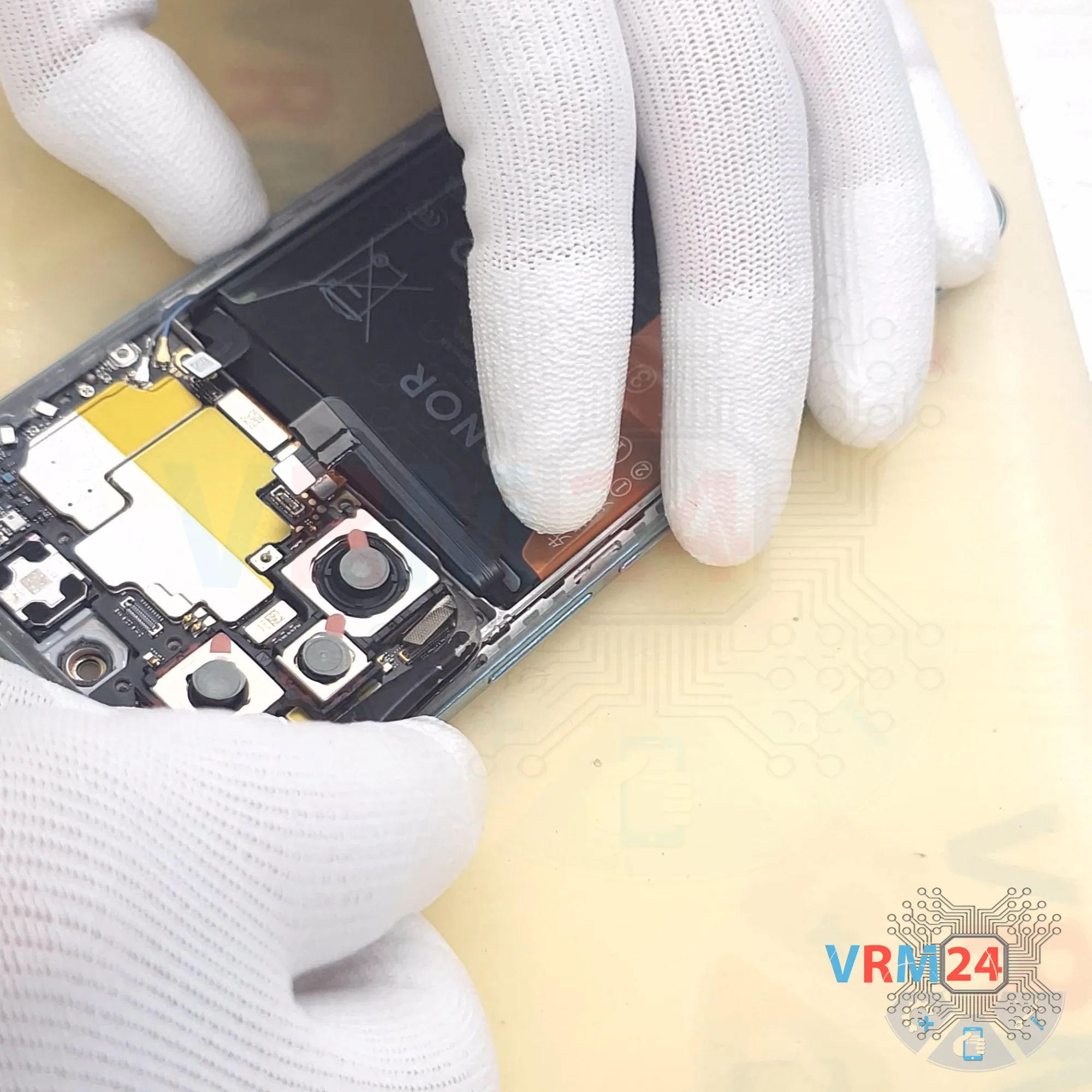
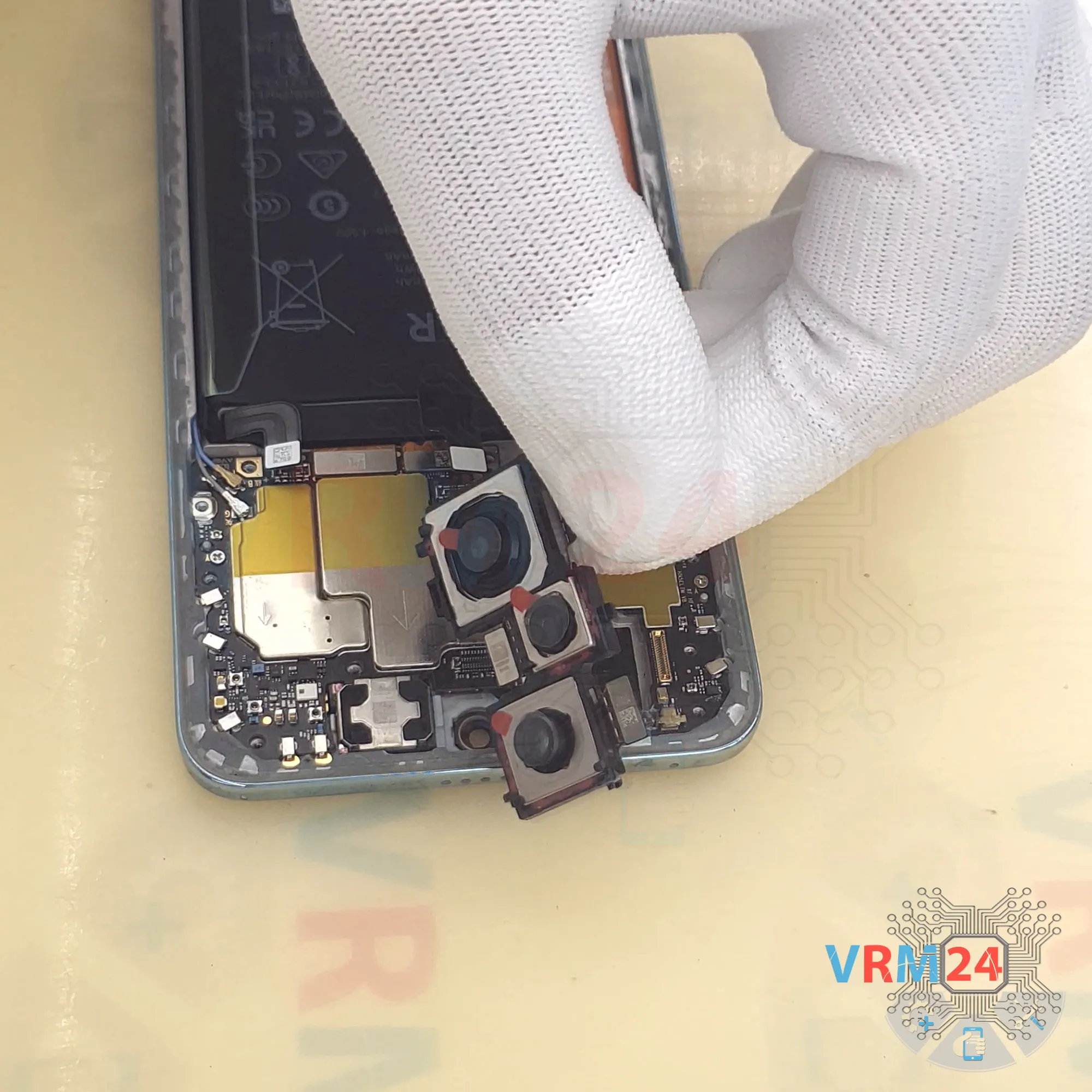
Step 13. Remove the cameras
First, we disconnect the front camera. Carefully pry it off and set it aside. Of course, it’s also better to cover the front camera lens to protect it from dust.
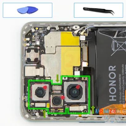
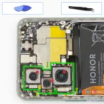
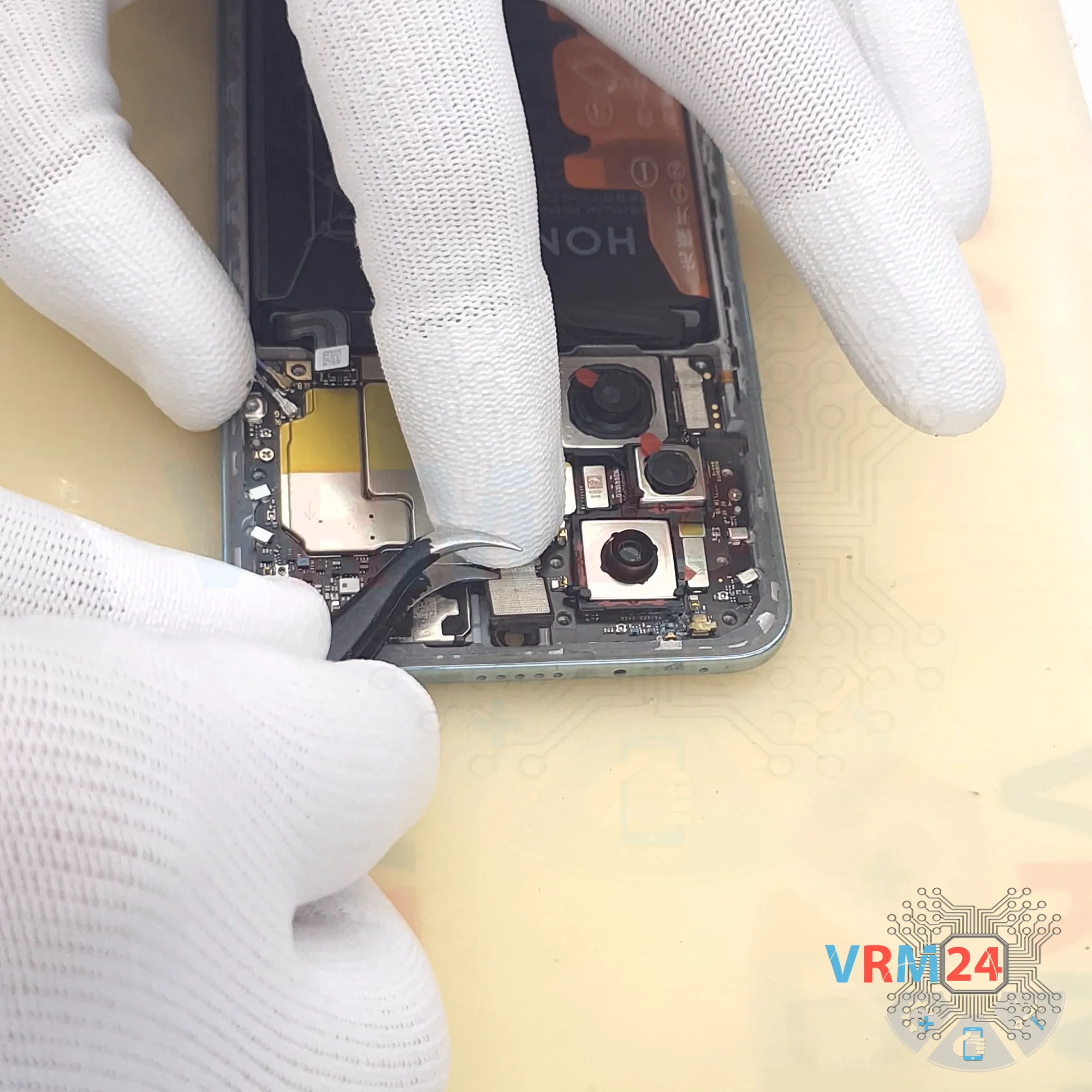
Next, disconnect the rear cameras. Gently disconnect their connectors.
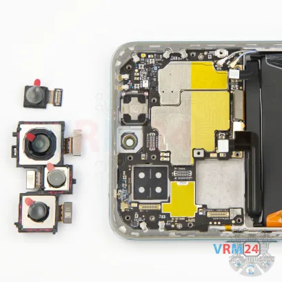
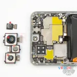
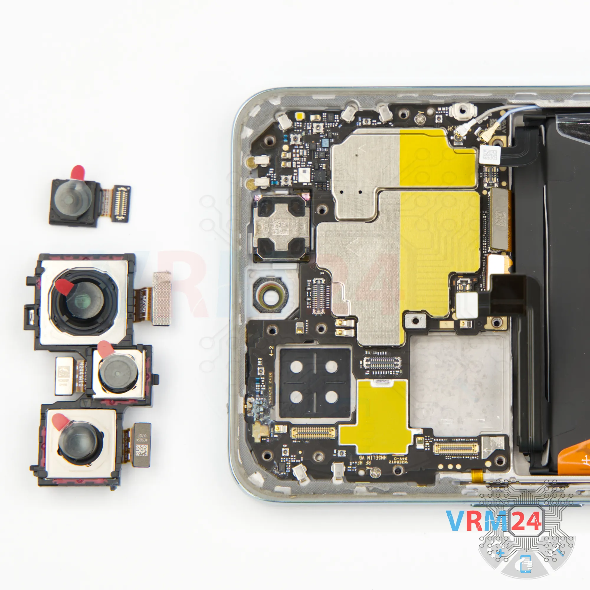
Check if the cameras are glued. As we can see, the cameras are set in a small frame, which can be removed easily.


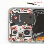
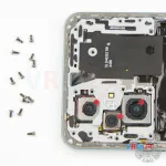
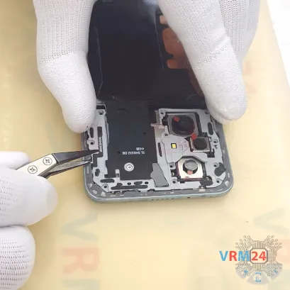
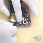
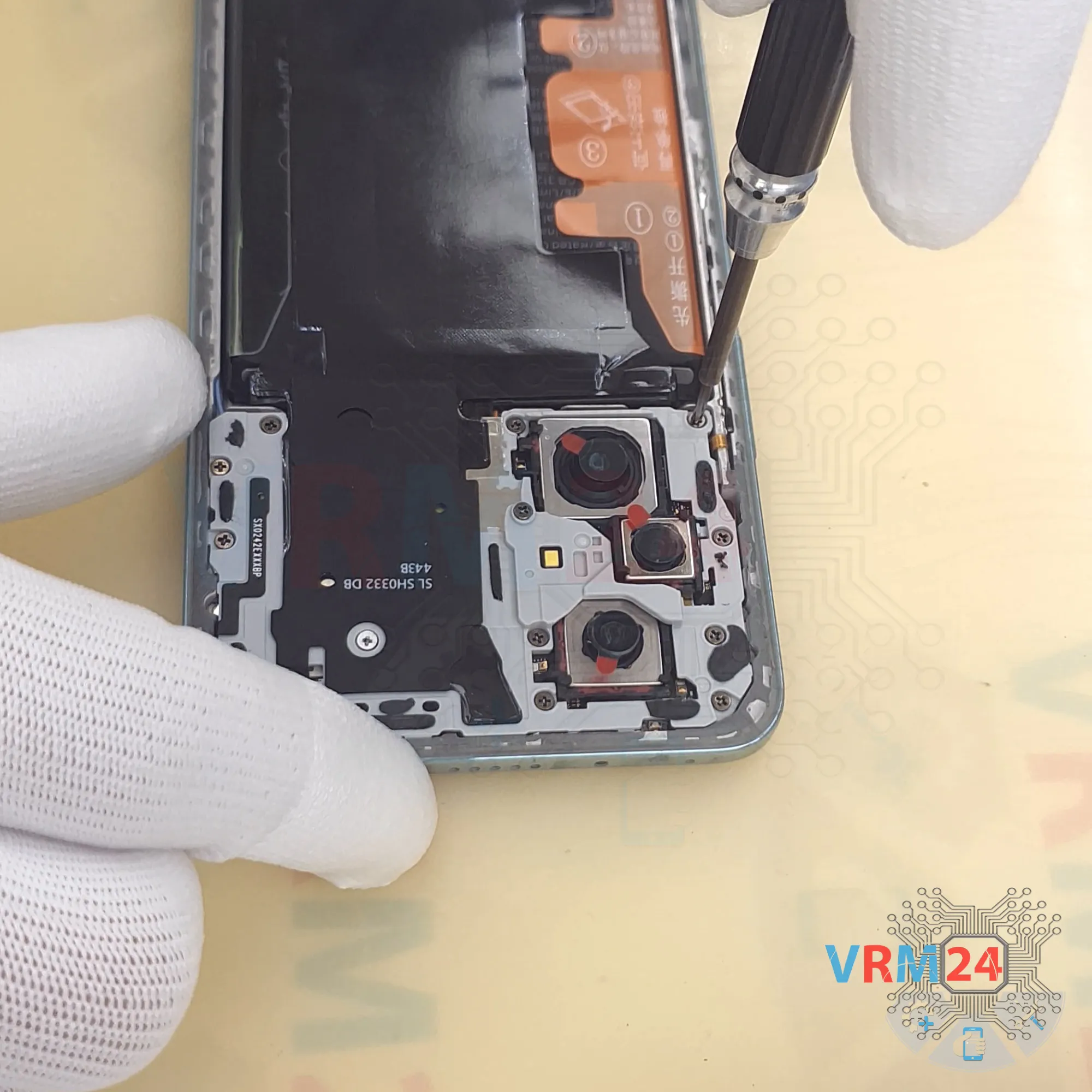
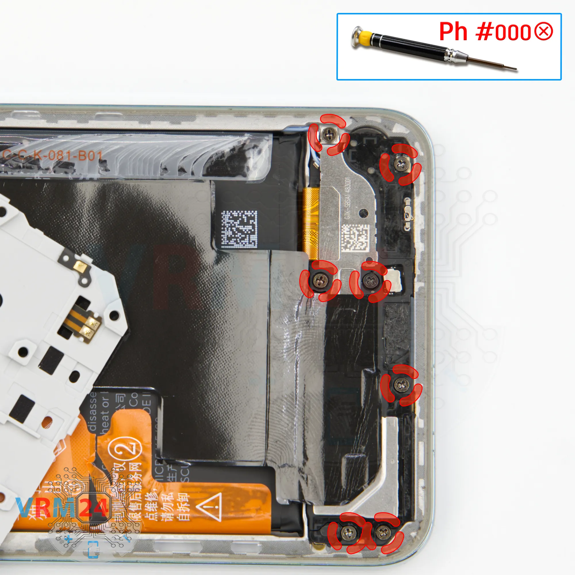
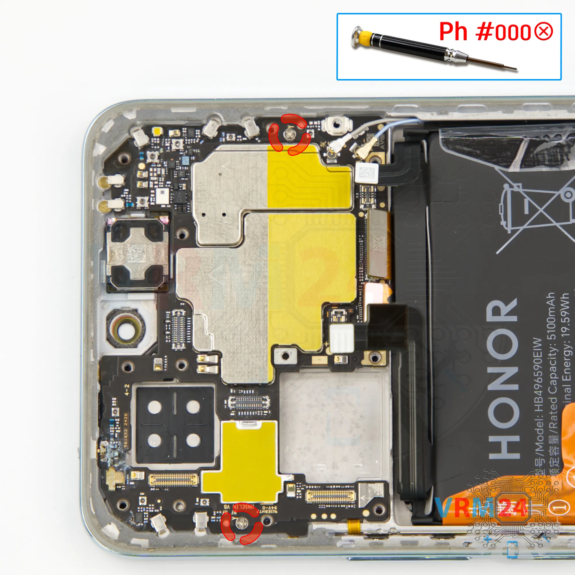
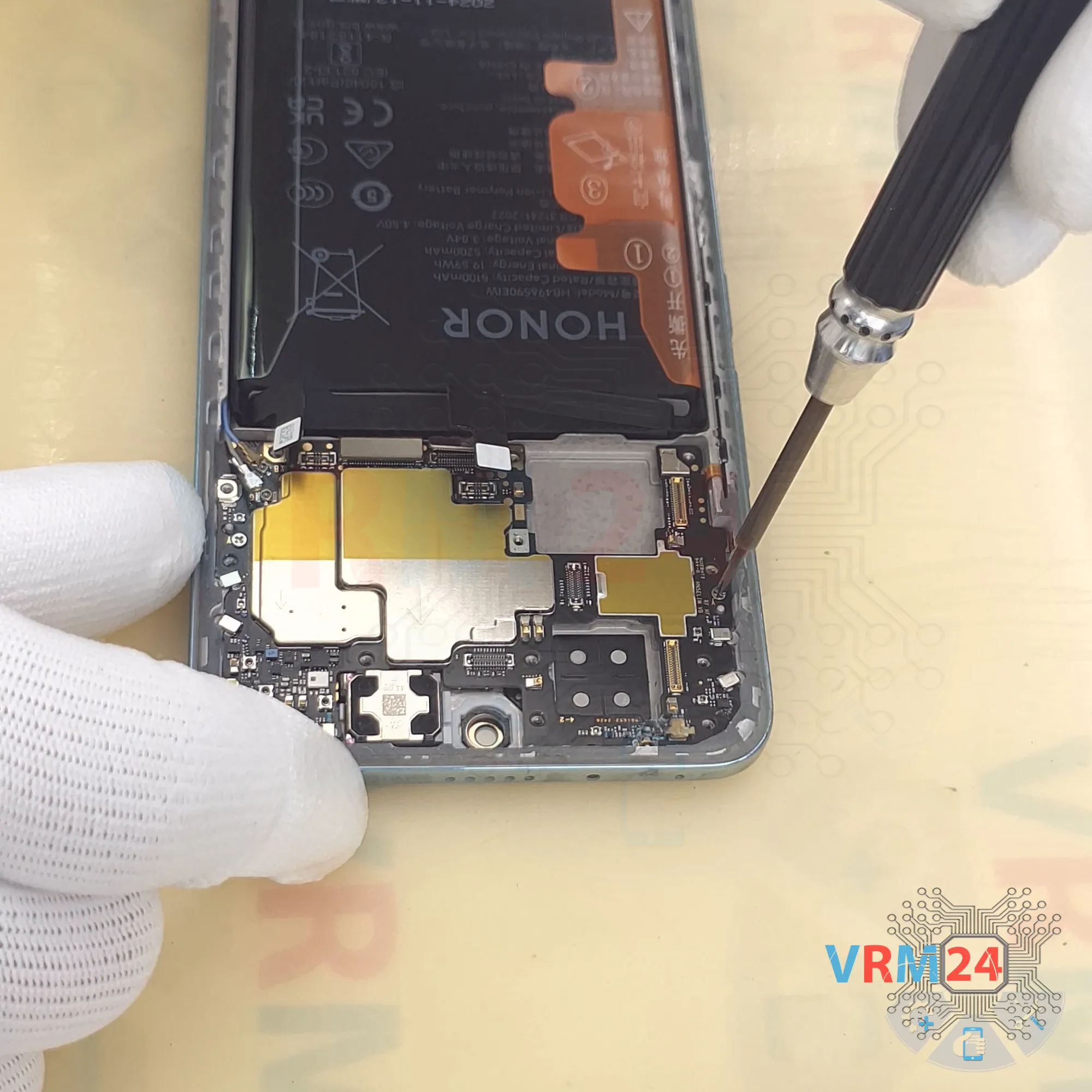
Step 14. Unscrew the screws
Let’s check for screws. Yes, there are screws we need to remove.
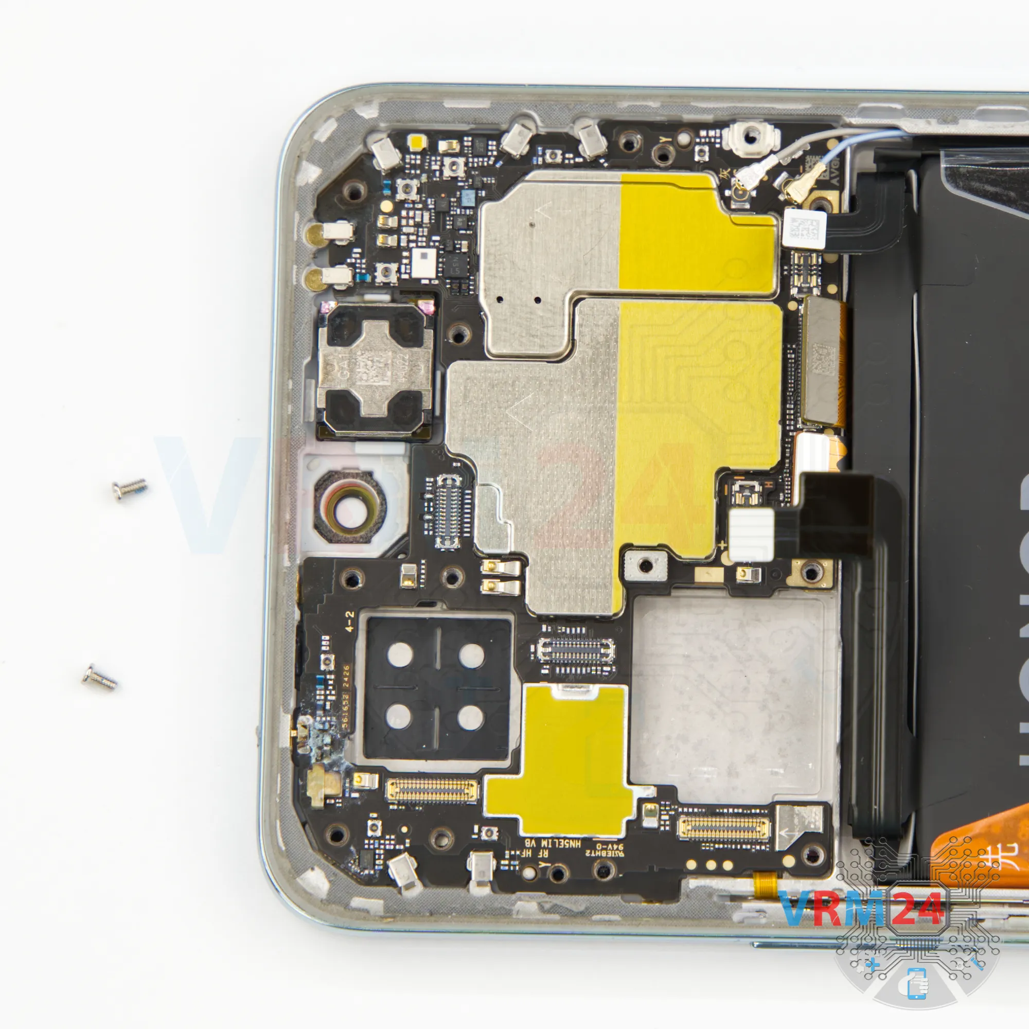
For this, we use the same 1.5 mm Phillips screwdriver. Carefully unscrew the two screws.
These screws are magnetic and clearly different from the previous ones. Set them aside.
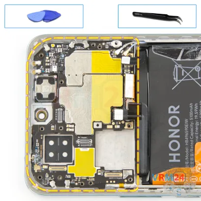
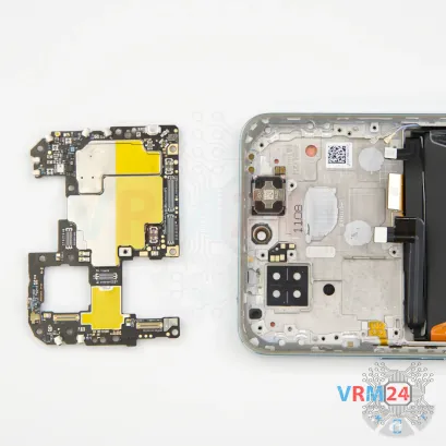


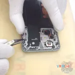
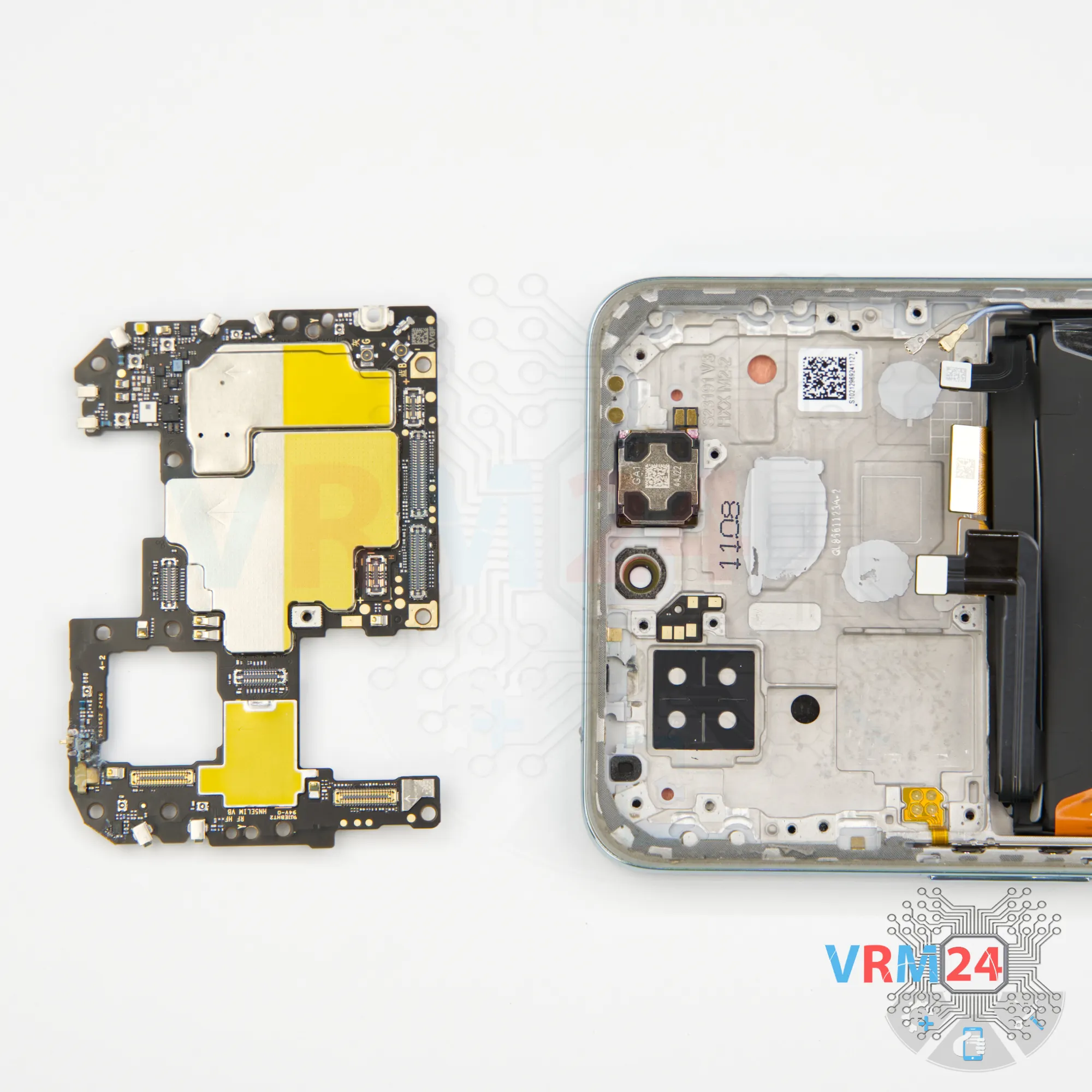
Step 15. Remove the motherboard
Now we can remove the motherboard. At the right spot, gently pry it up, lift, and take it out.
There is no need to use a lever or try to reach the circuit board by force. Make sure that nothing is getting in the way or holding the circuit board.
The motherboard, also, may be attached with attachments like latches or hooks, be careful.


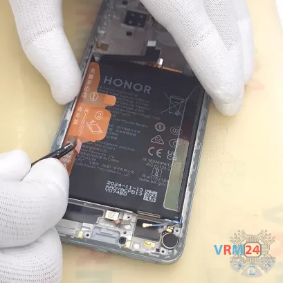
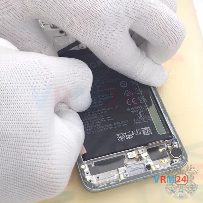

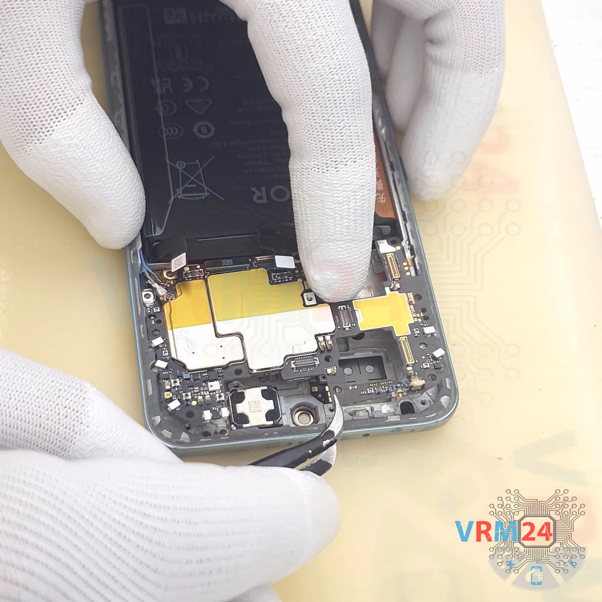
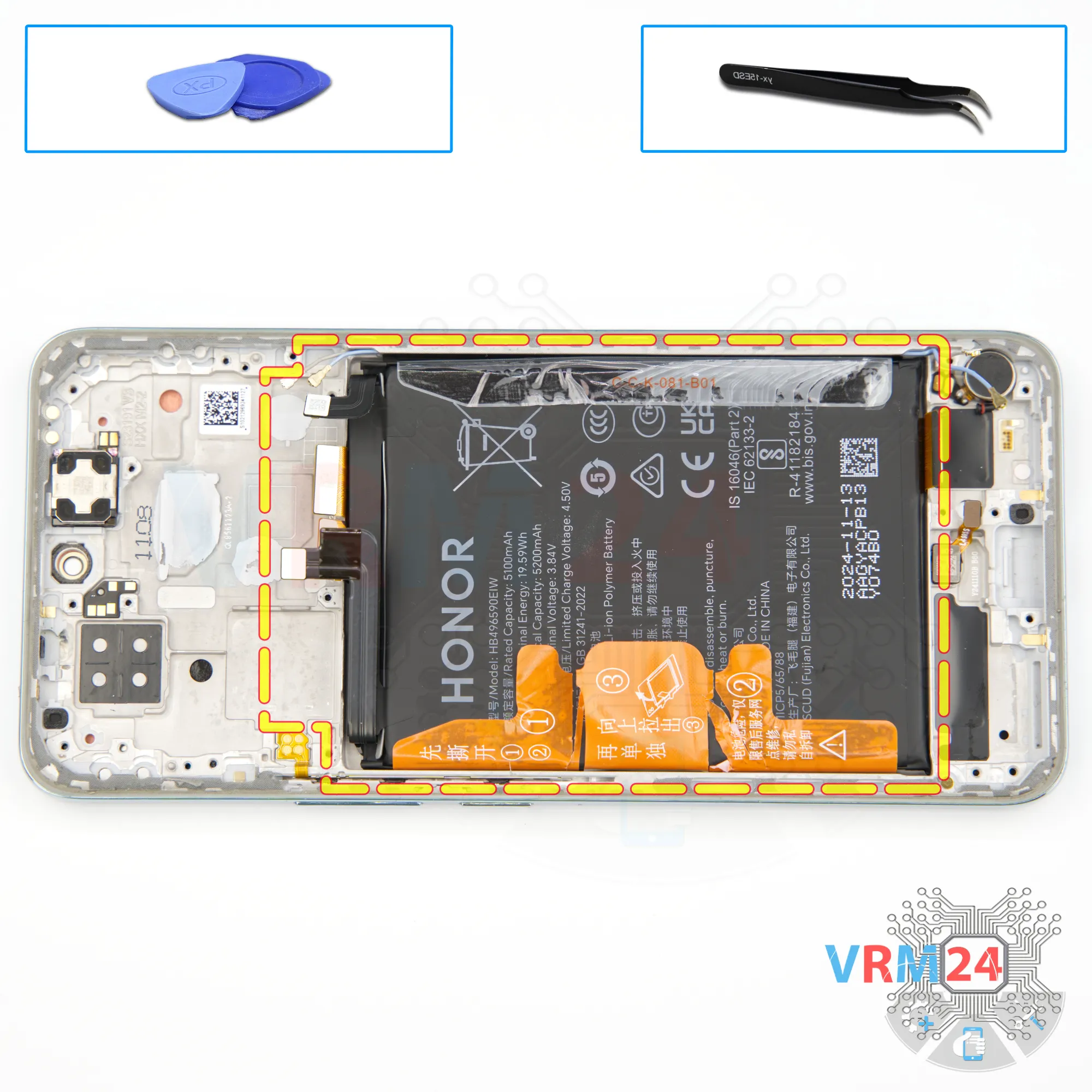
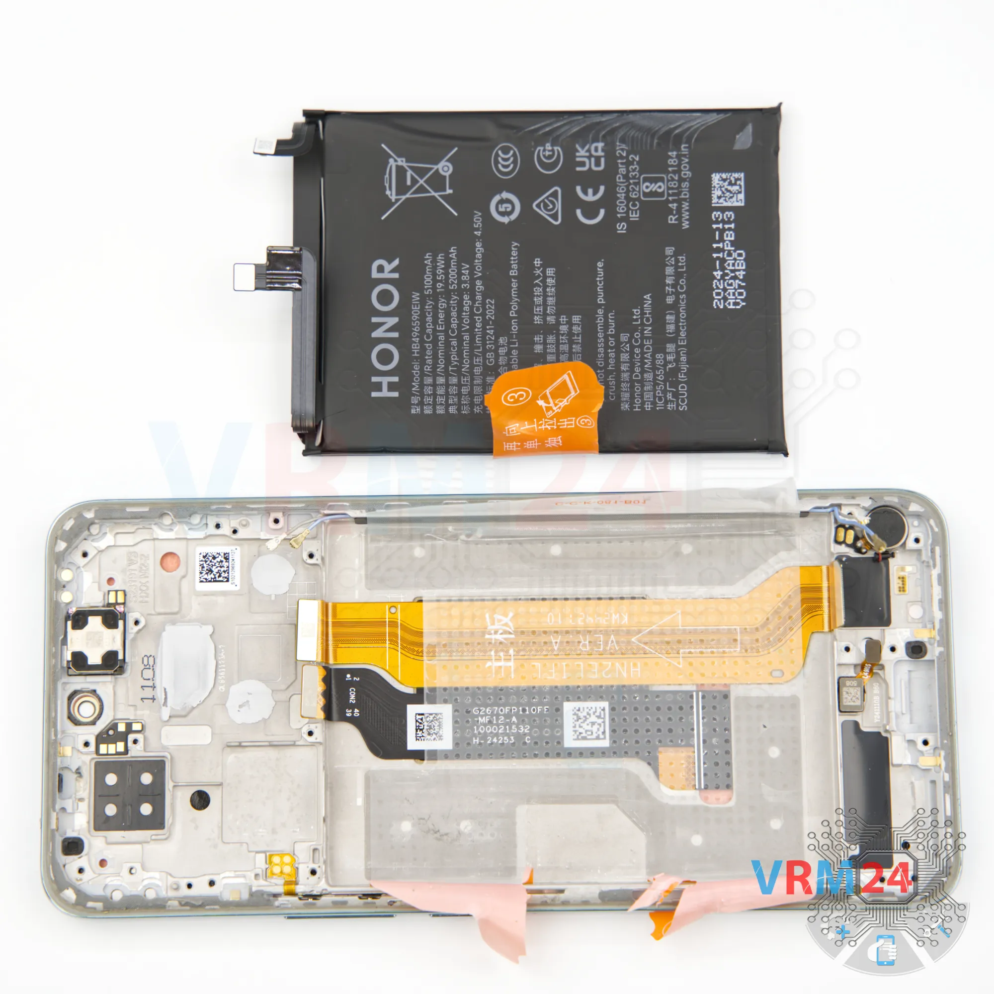
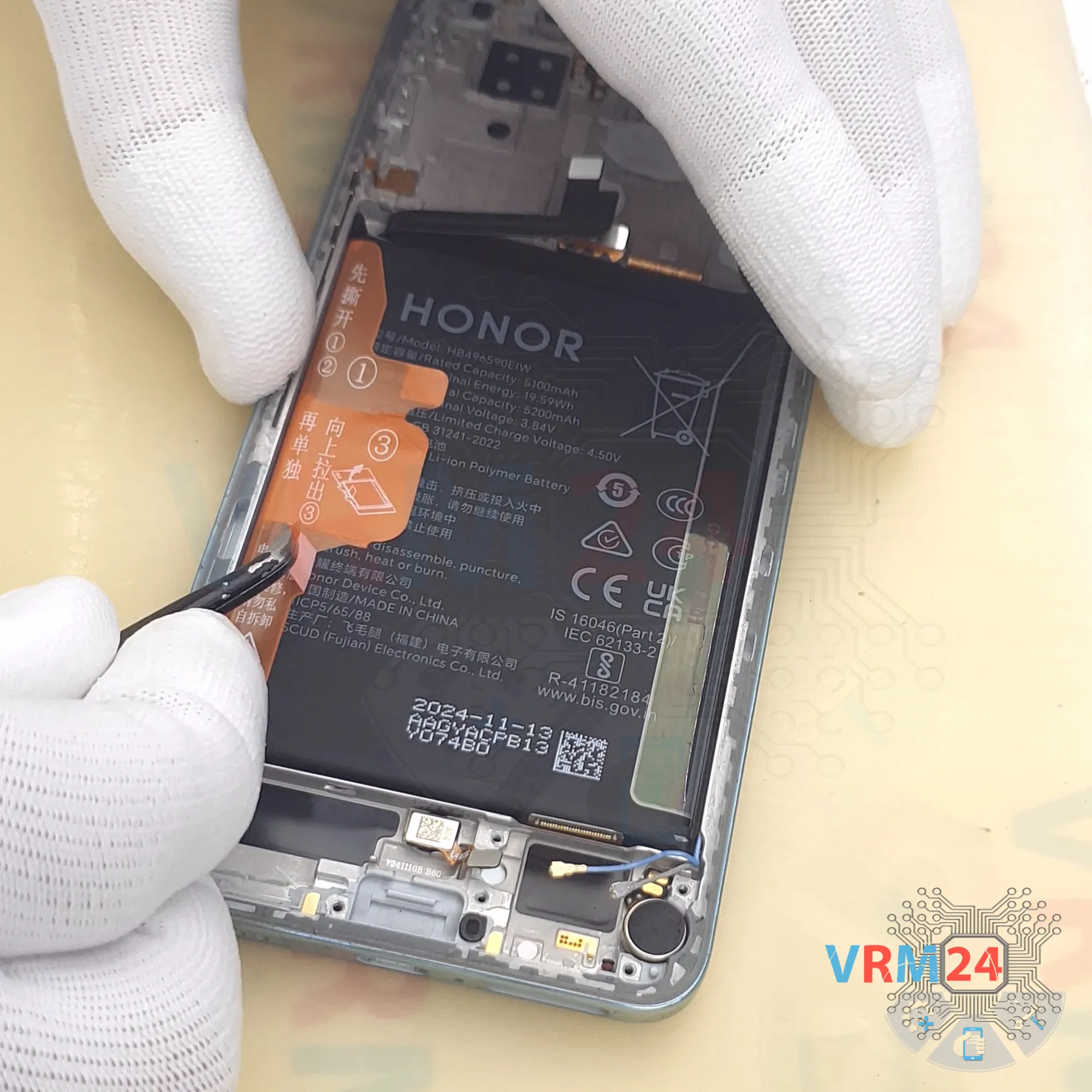
Step 16. Remove the battery
And finally, we move on to removing the battery.
As usual for HONOR, there are brown pull-tabs, which are hard to detach and often tear. Carefully fold them back.
Of course, always read the instructions.
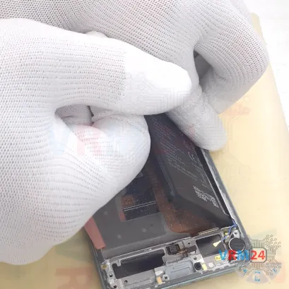
The side tabs need to be folded back, while the middle tab needs to be pulled upward.
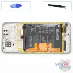
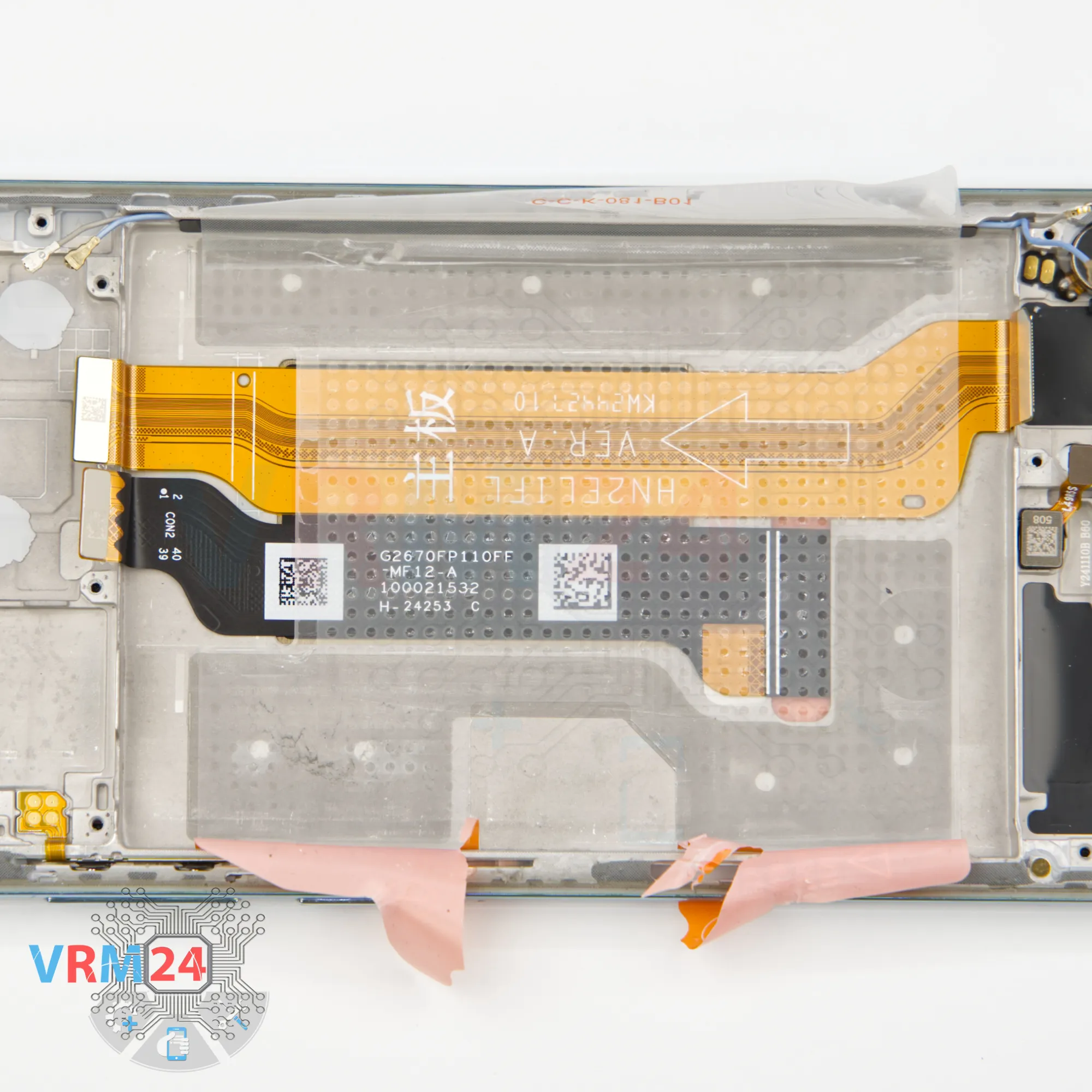
Underneath the battery there’s a transparent layer that protects the Interconnect cables.


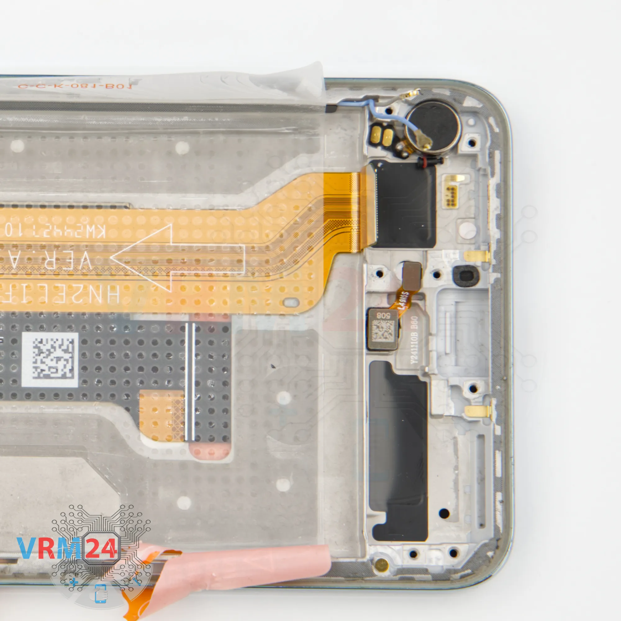
Step 17. In the display frame remained
ℹ️️ In the display frame remained: the earpiece speaker, fingerprint sensor, vibration motor and cables.
Detailed disassembly instructions of HONOR 200 in the video, made by our mobile repair & service center:
If you have a question, ask us, and we will try to answer in as much detail as possible. If this article was helpful for you, please rate it.

Disassembling\Repair has medium complexity and takes about minutes in time.
Our manual is suitable for all models HONOR 200 — HONOR 200 ELI-NX9 released for markets in different countries.
Back to the list