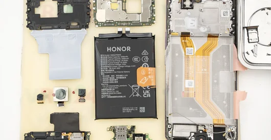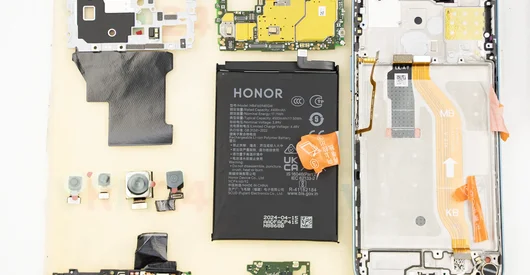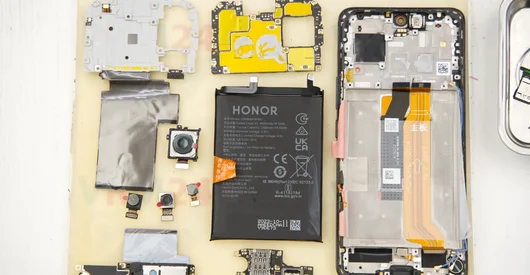
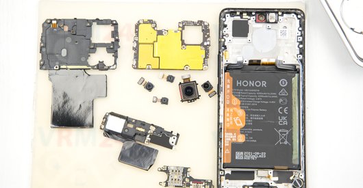

Recommended tools
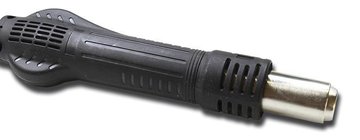
Heat gun
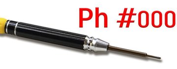
Screwdriver Phillips #000
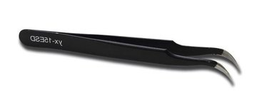
Tweezers
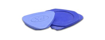
Non-metallic tool
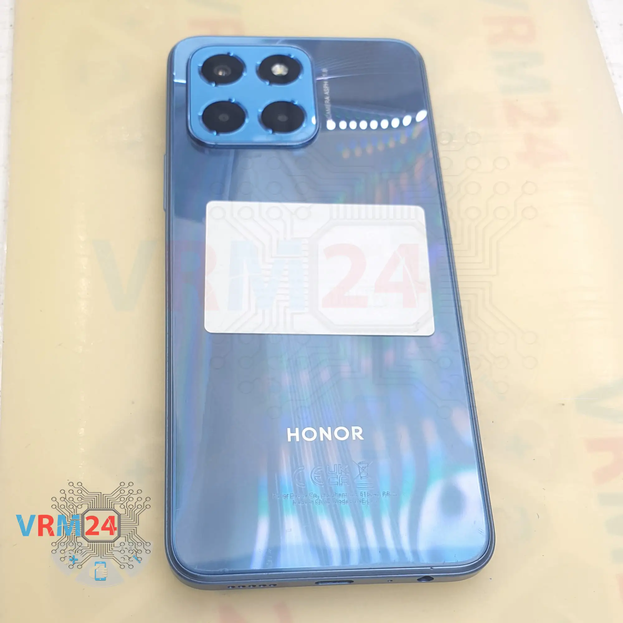
Disassembly/Repair of the mobile device Honor X6 (Honor X6 VNE-LX1) with each step description and the required set of tools.
12065
Views
2
Likes
—
Share
1
Questions

Step 1.
Before disassembling!
⚠️ Before disassembling, do not forget to turn your phone off.
Step 2.
Remove the tray
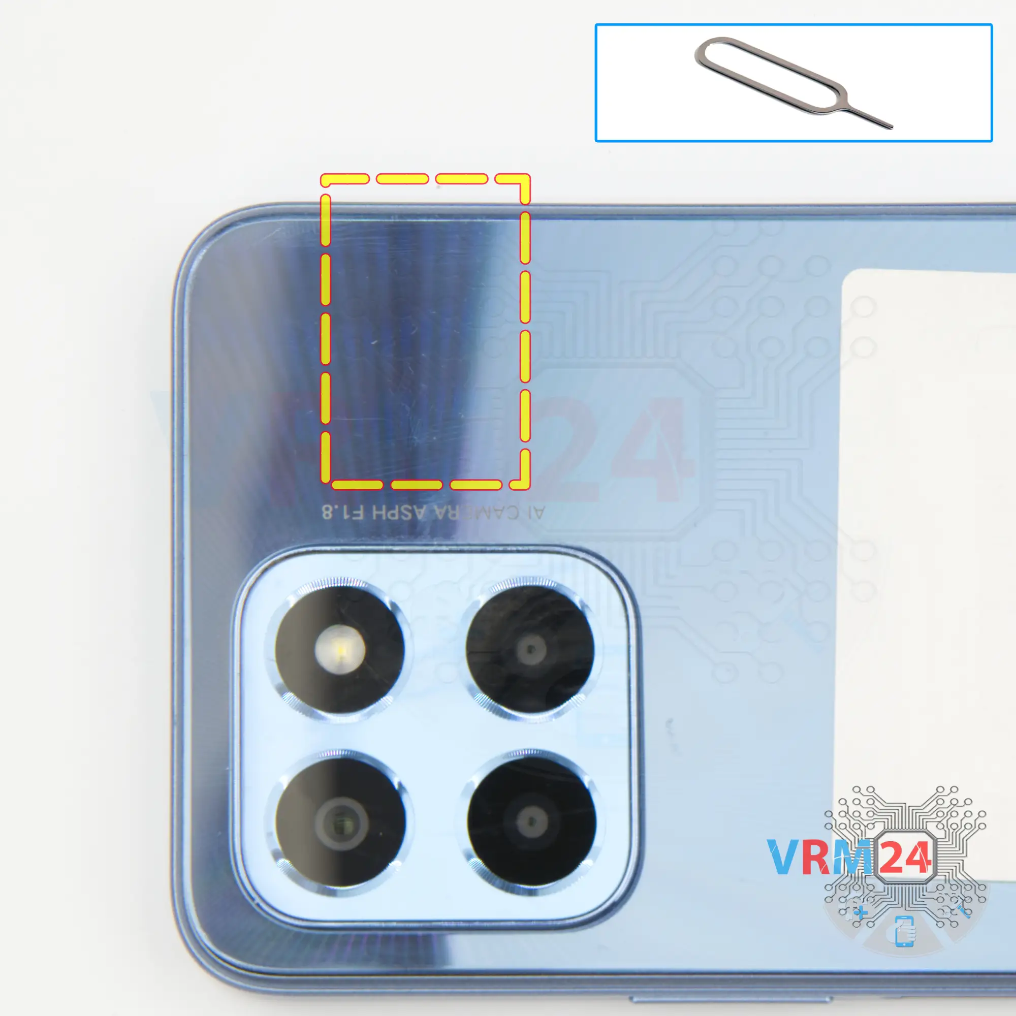
First of all, we need to remove the card tray. To do this, we use a special tool, insert it into the hole and carefully push out the card tray.
If the tray does not come out well, we can additionally use tweezers.
Step 3.
Remove the motherboard
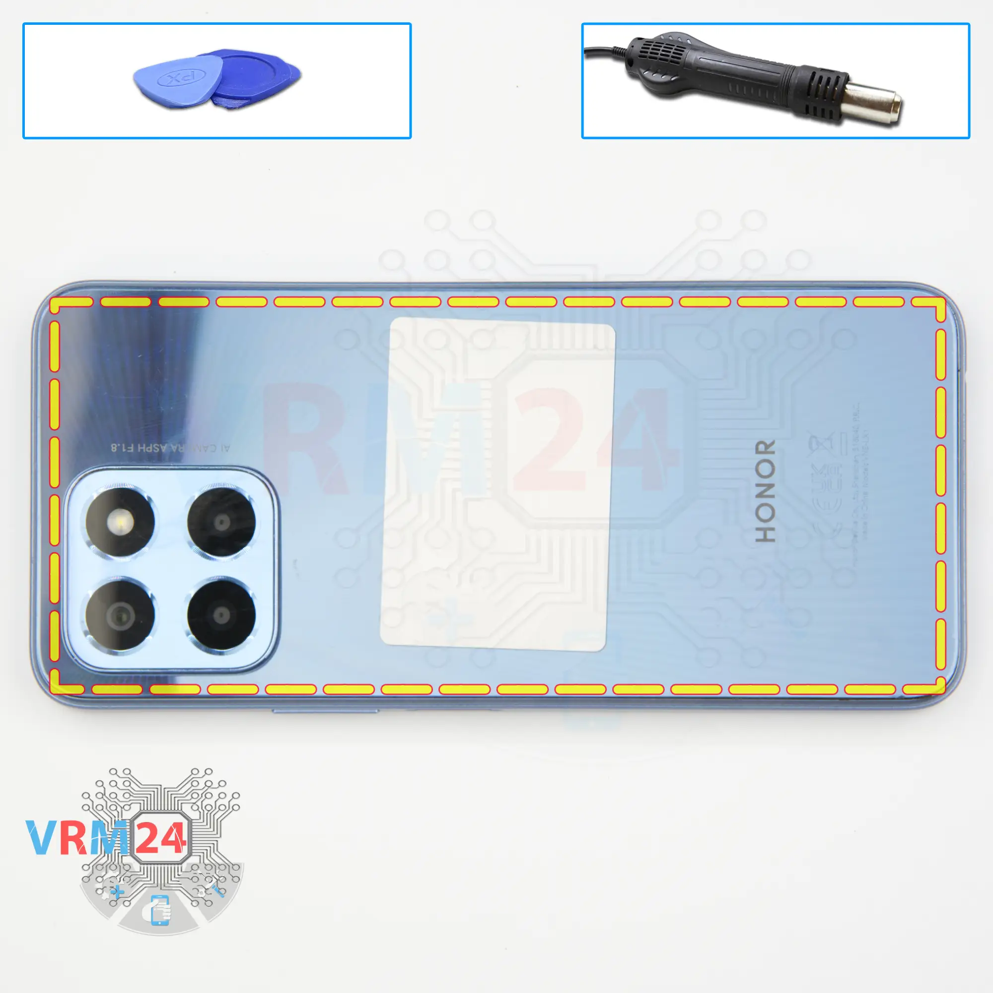
We need to heat the surface of the back cover to a temperature of approximately 70 degrees Celsius or 160 degrees Fahrenheit. For this we use a heating mat, you can use a hair dryer.
And after 5 to 7 minutes, we can move on to detaching the back cover. To detach the back cover, we use a thin plastic film, but first we use a thin metal tool to create a small gap between the middle cover and the back cover, where we insert the thin plastic film and start running the plastic film along the edge, cutting off the adhesive base.
Usually, we need to be careful around the cameras when detaching the back cover, but in our case the camera cover comes separately and the back cover is glued around the camera cover, so that's something we need to pay attention to.
Step 4.
Unscrew the screws
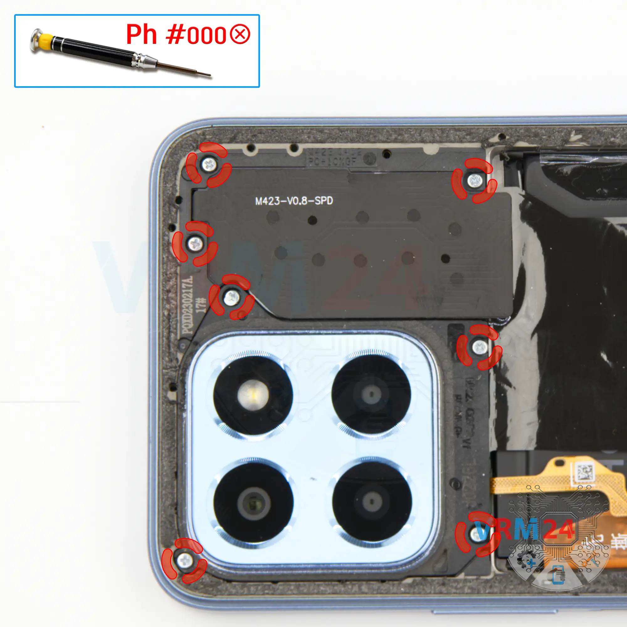
Then we move on to unscrewing the seven screws. For this we use a one and a half millimeter Phillips screwdriver or Phillips #000.
Carefully unscrew the screws and place them on a special surface in a certain order so that they do not get mixed up when reassembling.
Step 5.
Remove the camera cover
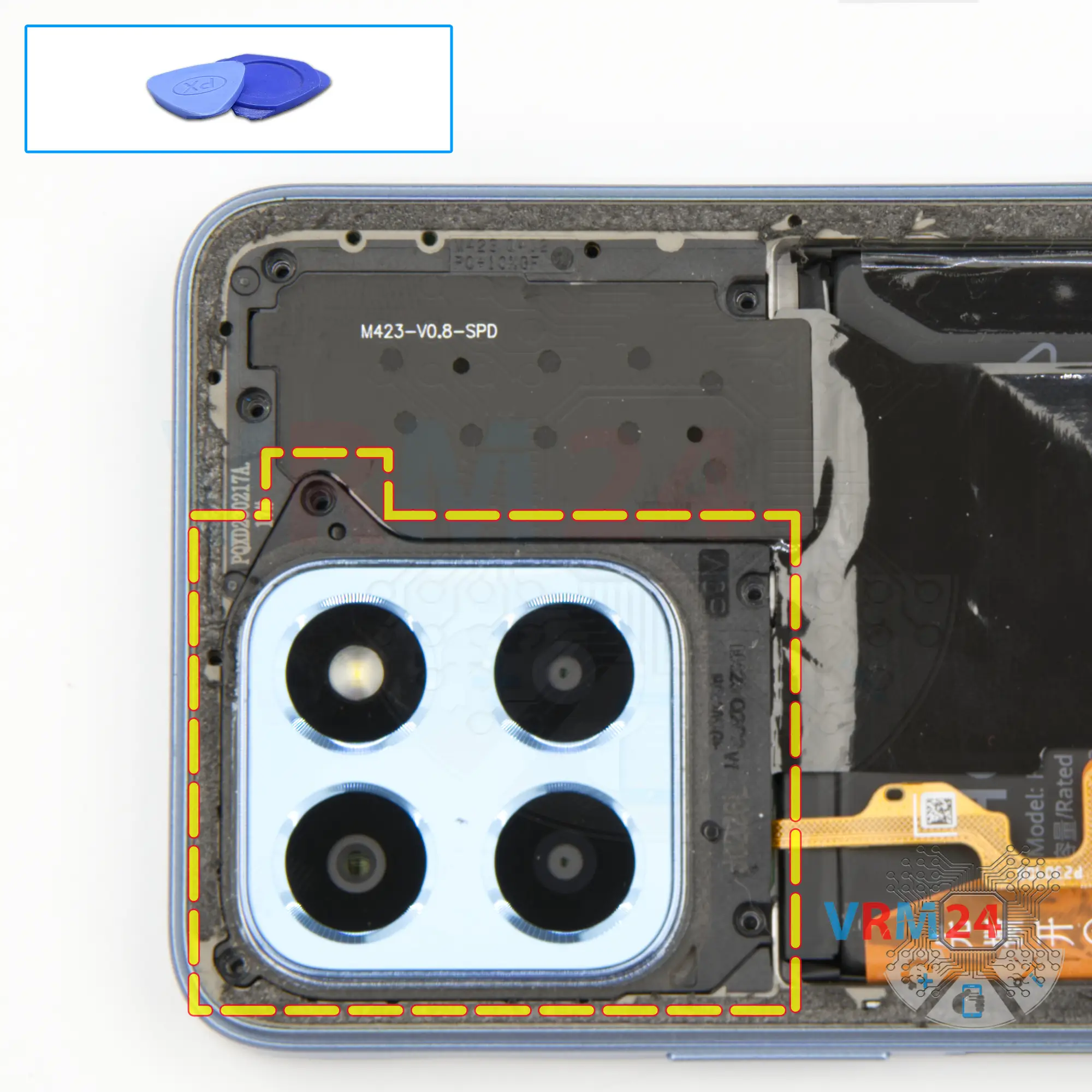
We need to detach the camera cover. We find the right place where we can pry and detach the cover.
On the cover we have the flashlight elements.
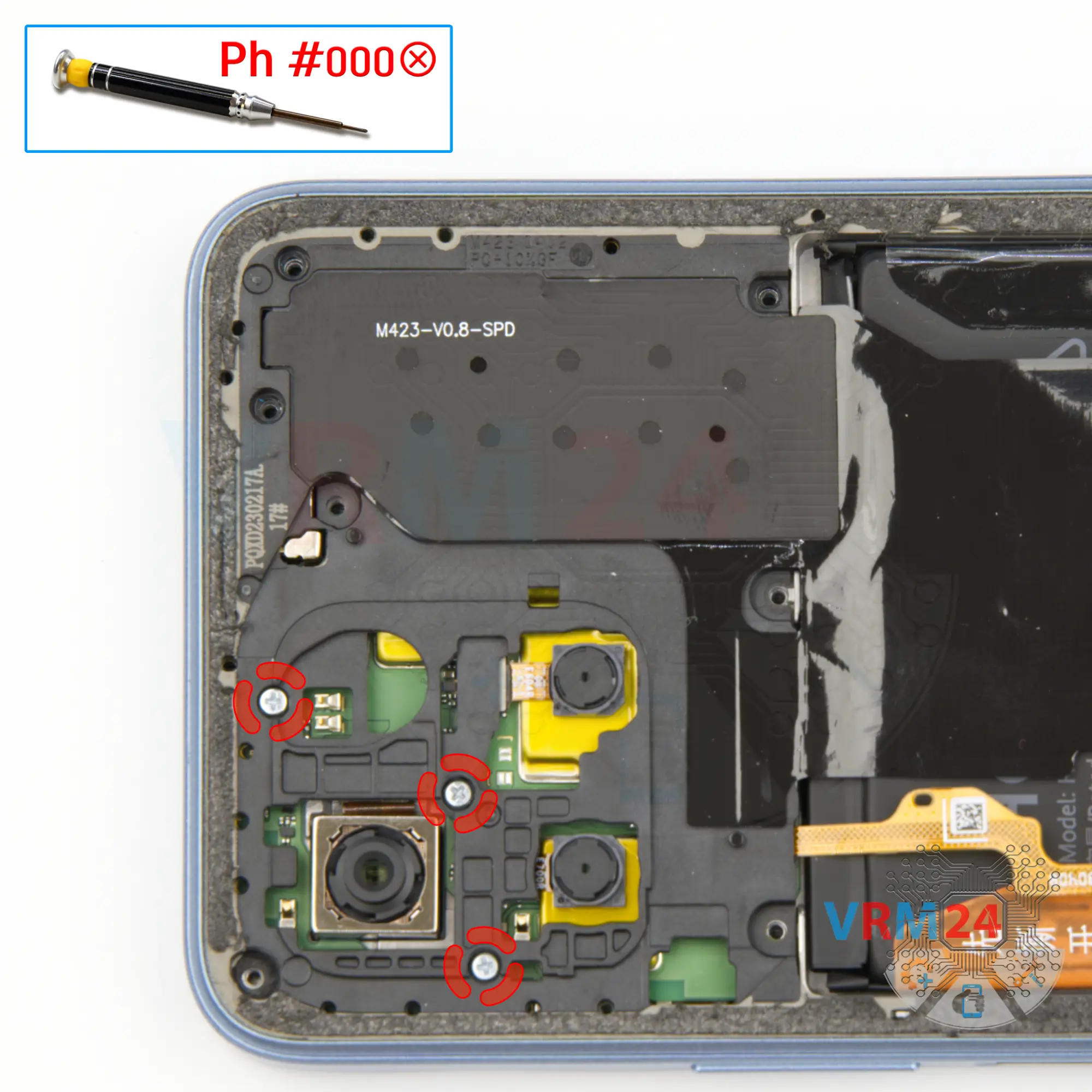
Under the cover we have a few screws that need to be unscrewed, which also hold the middle cover.
Step 6.
Unscrew the screws
Carefully unscrew the three screws, place them on a special surface so that they do not get mixed up when reassembling.
Step 7.
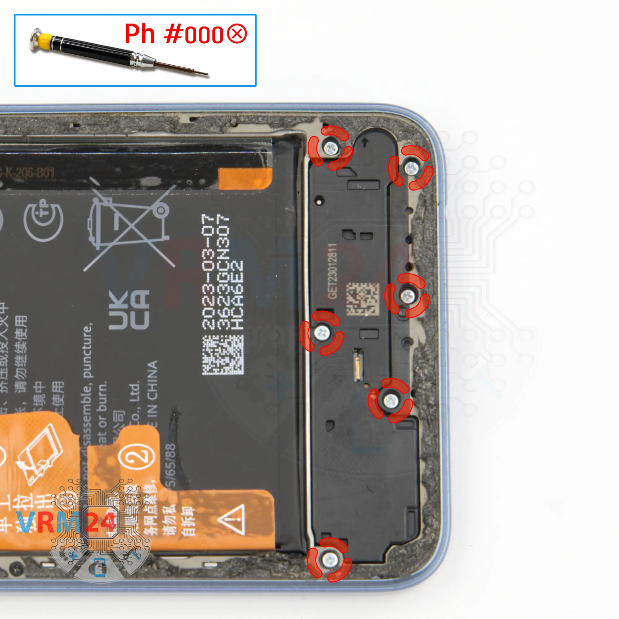
Unscrew the screws
Then we unscrew the screws at the bottom.
Using a screwdriver Phillips 1.5 mm (PH #000), unscrew the six screws.
Step 8.
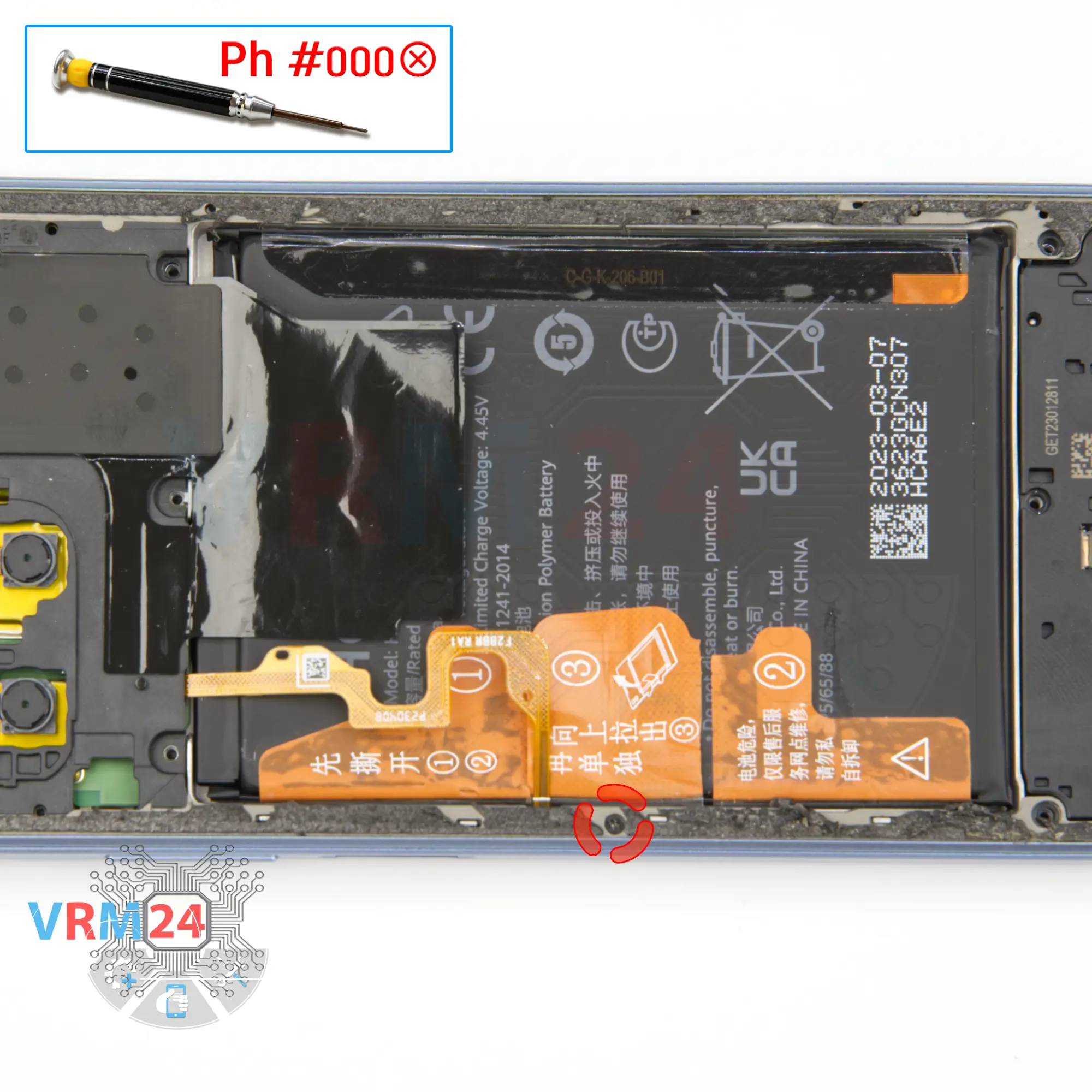
Unscrew one screw
And we also need to remove one screw, which is hard to notice, and it also holds the middle cover.
Step 9.
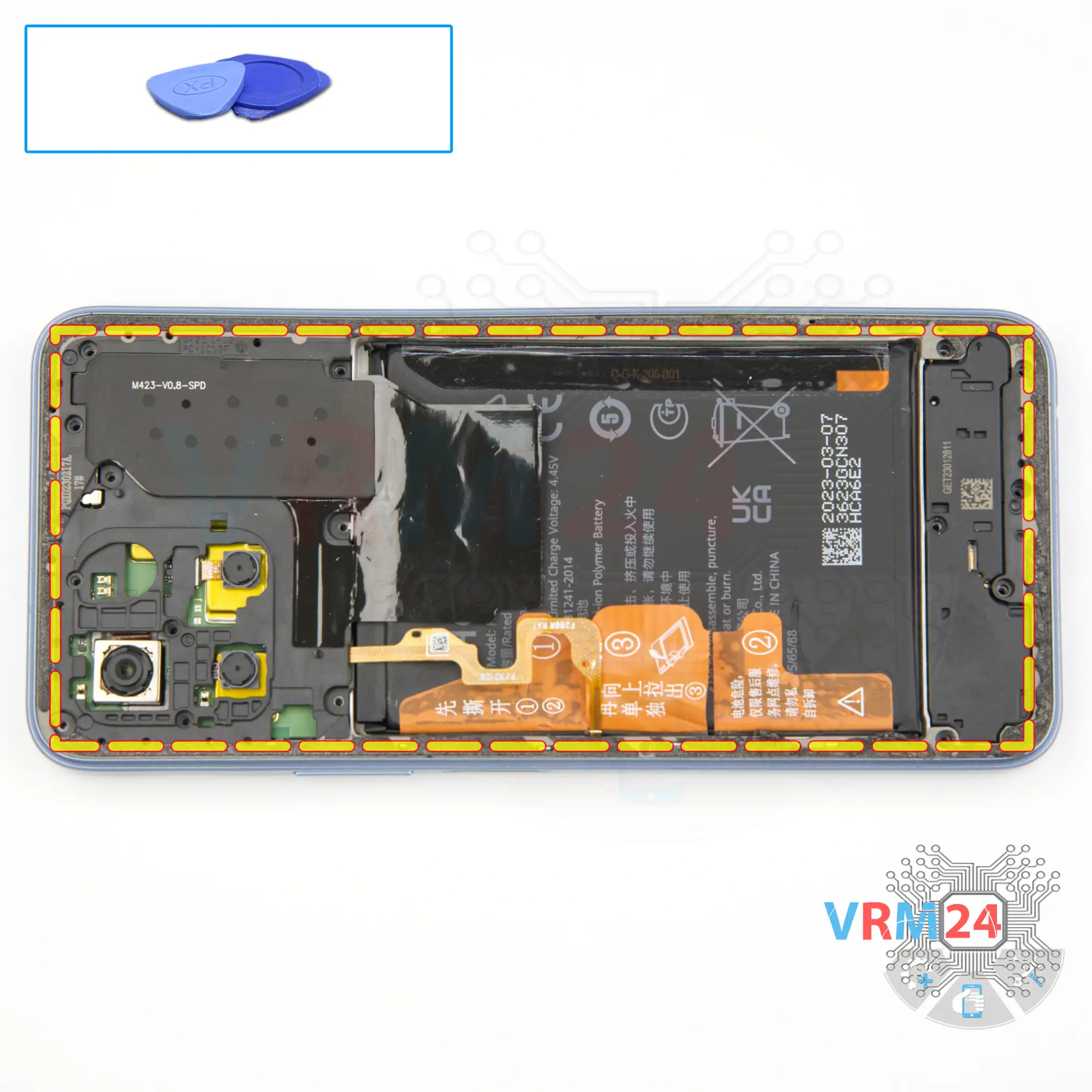
Open the mid-frame
So, after unscrewing the screws, we move on to detaching the middle cover.
At first, we use a thin plastic film, insert it into the gap between the display frame and the middle cover in the area of the card tray, unclip a few clips and then we can use a thicker tool. Carefully pass the tool along the edge, unclip the clips, thereby detaching the middle cover.
As always, we need to be careful around the side buttons, because they are physically located there, and of course we need to be careful on the corners, because the cover is held especially tightly on the corners.
Step 10.
Disconnect the connector
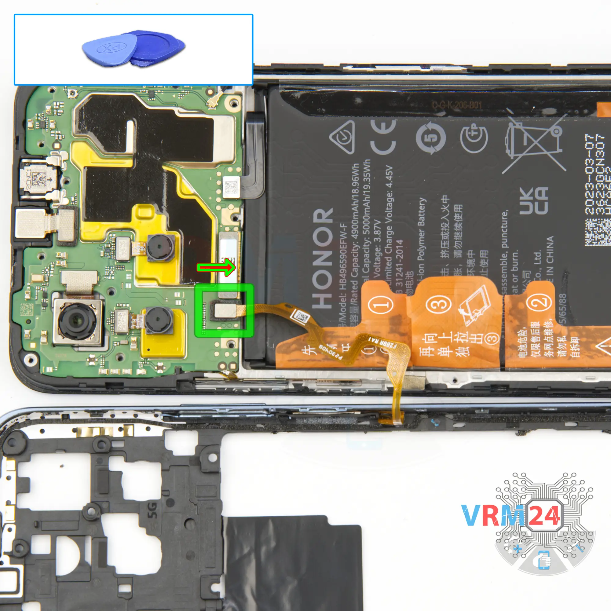
After detaching the cover, we need to disconnect the fingerprint sensor connector and we can remove the middle cover.
Step 11.
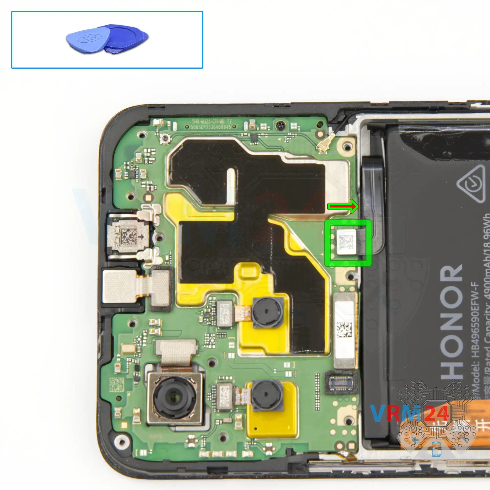
Disconnect the battery connector
Disconnect the battery connector as soon as you can. Use a non-metallic or plastic tool to avoid any damage.
ℹ️ The Honor X6 VNE-LX1 model has a battery HB496590EFW-F with a capacity of 5000 mAh (also known as a rechargeable battery).
Step 12.
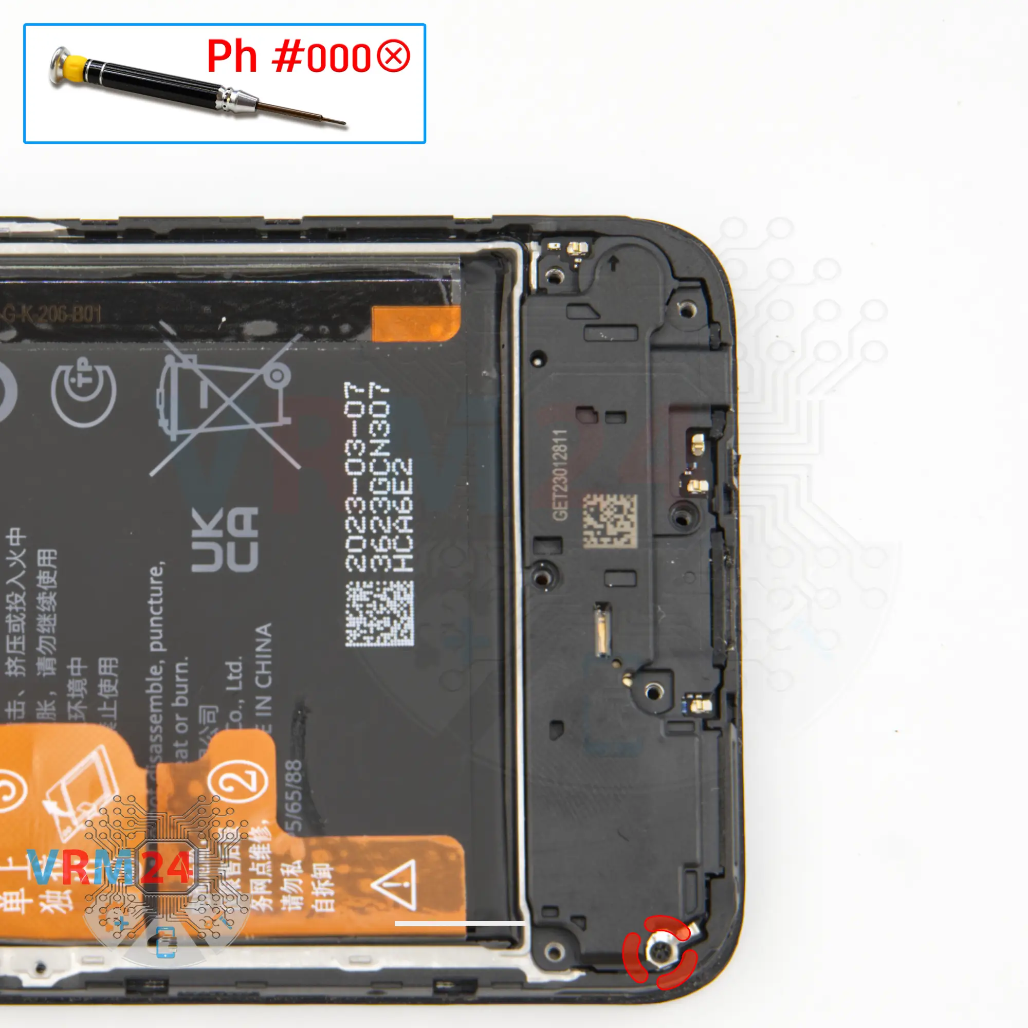
Unscrew one screw
We can see we have another screw, which is obviously different from the previous ones, which was previously hidden by the middle cover and which also holds the cover with the speaker and the antenna element.
We unscrew this screw and put it aside.
Step 13.
Remove the loudspeaker
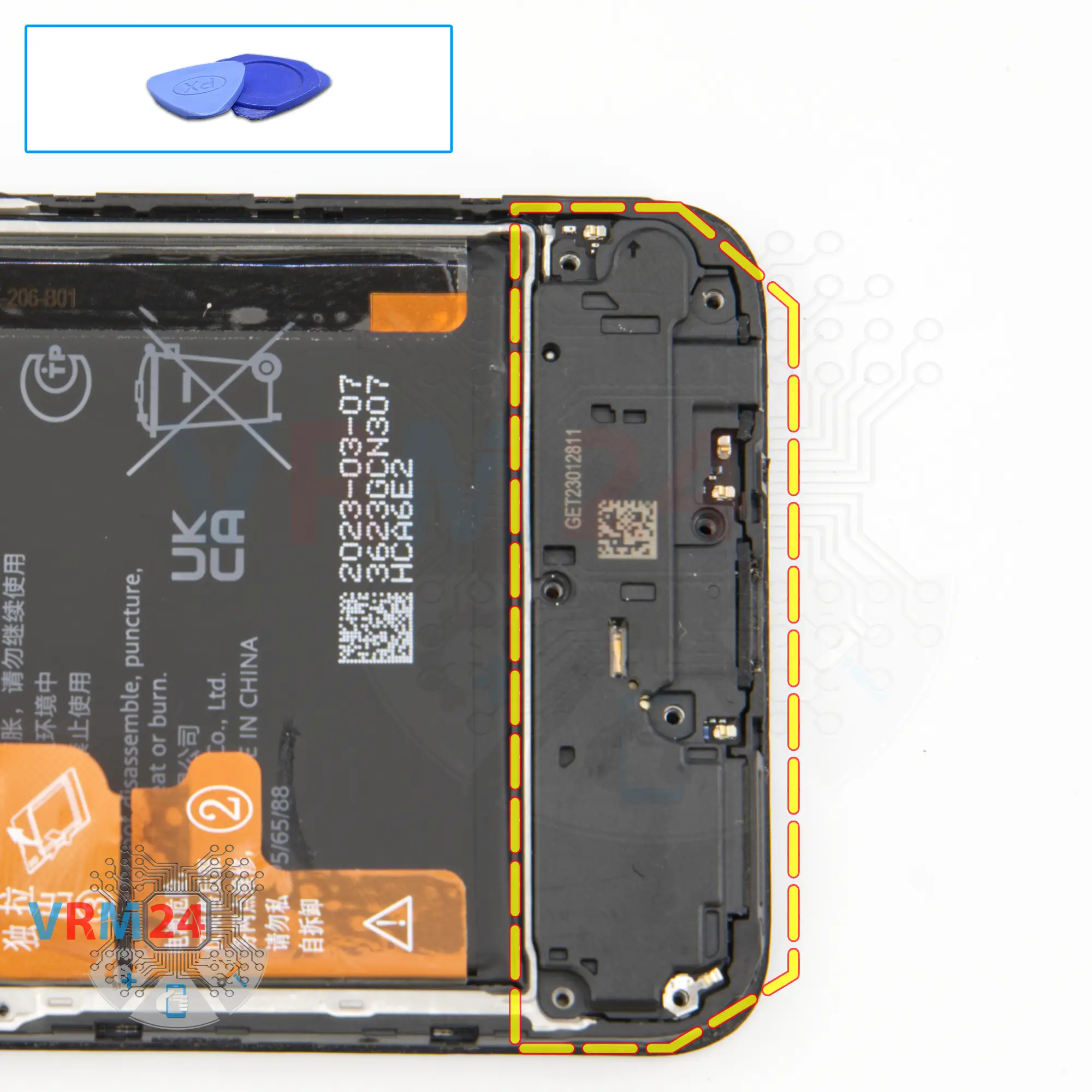
And we move on to detaching the cover with the speaker. Carefully hook the edge and remove the cover.
Only the loudspeaker is located on the cover.
Step 14.
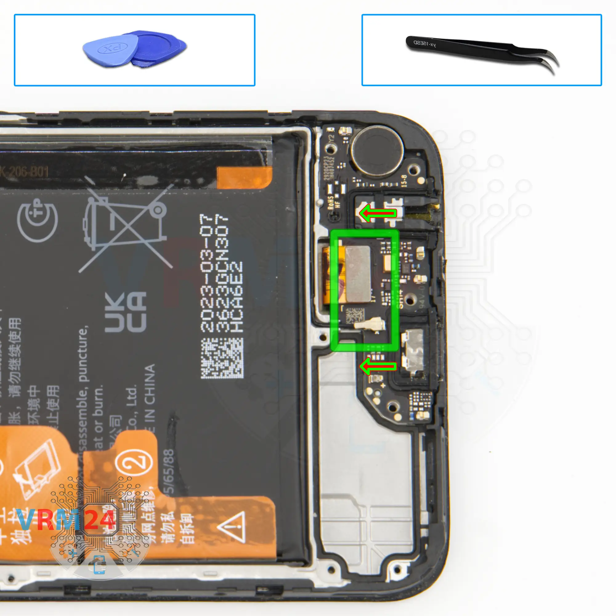
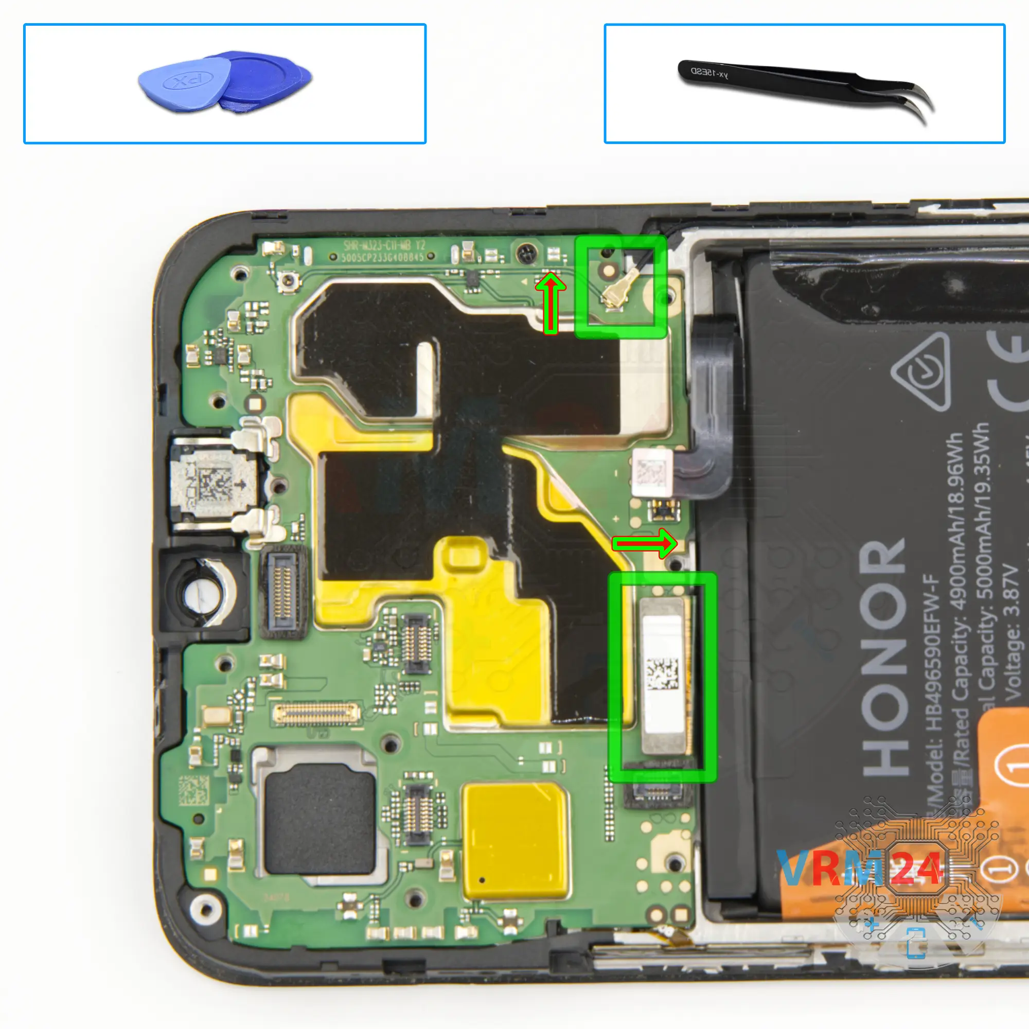
Disconnect the connectors
We can disconnect the coaxial cable connector, disconnect the inter-board cable connector on the sub-board.
Step 15.
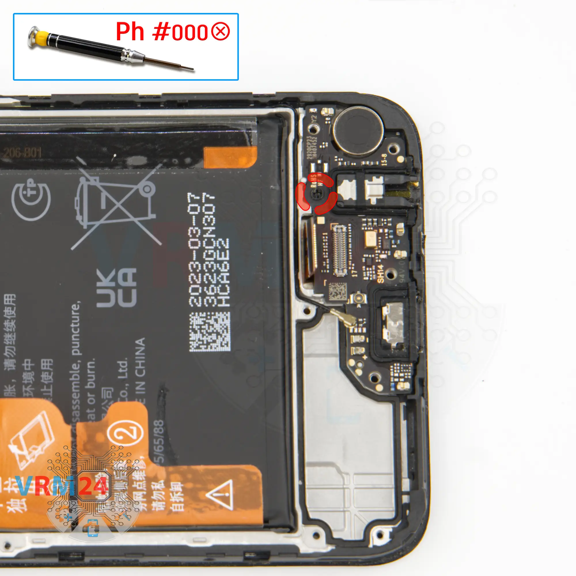
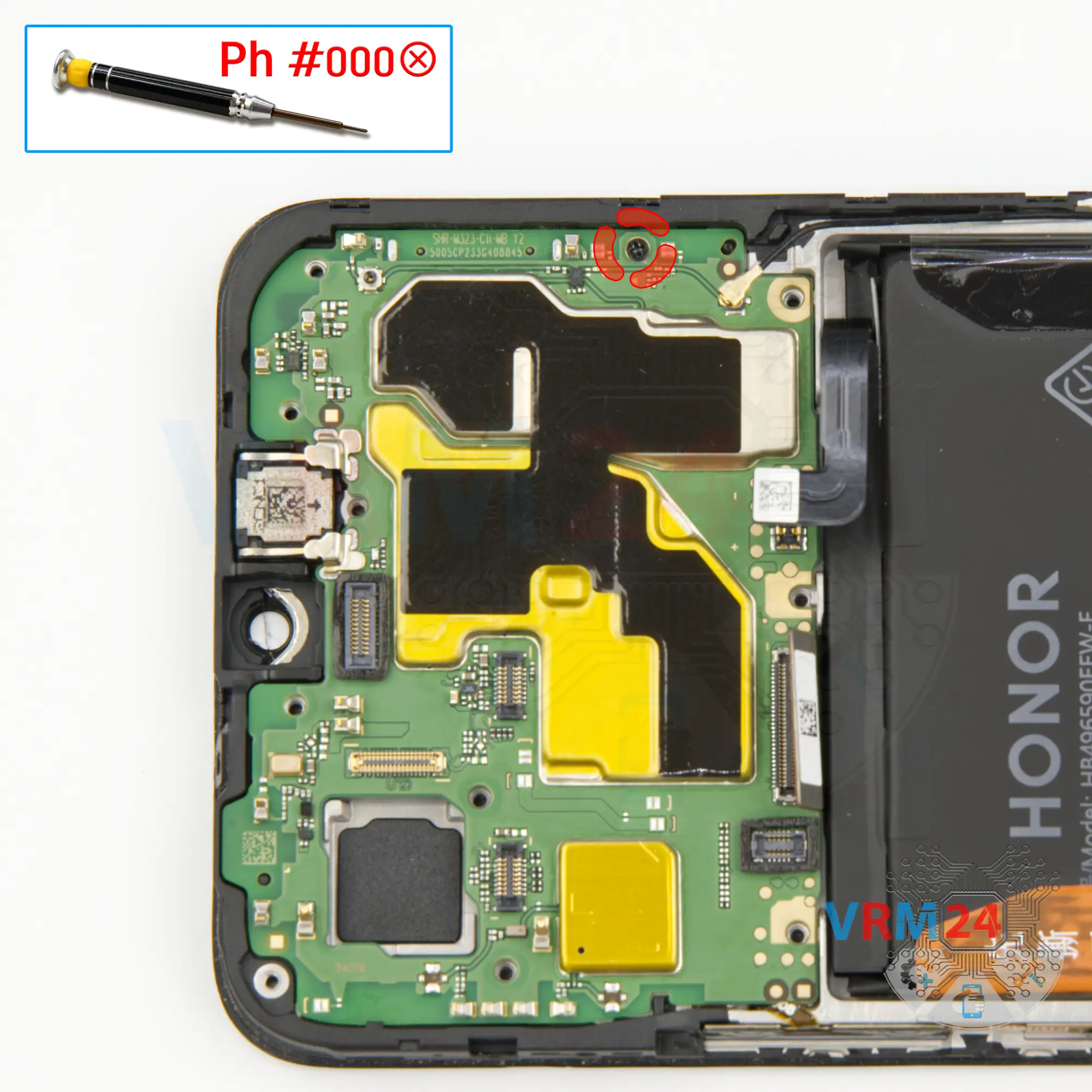
Unscrew one screw
And we also need to remove one screw that holds the sub-board in place.
As we can see a lot of screws are different, so they need to be located separately so that nothing gets mixed up.
Step 16.
Remove the sub-board
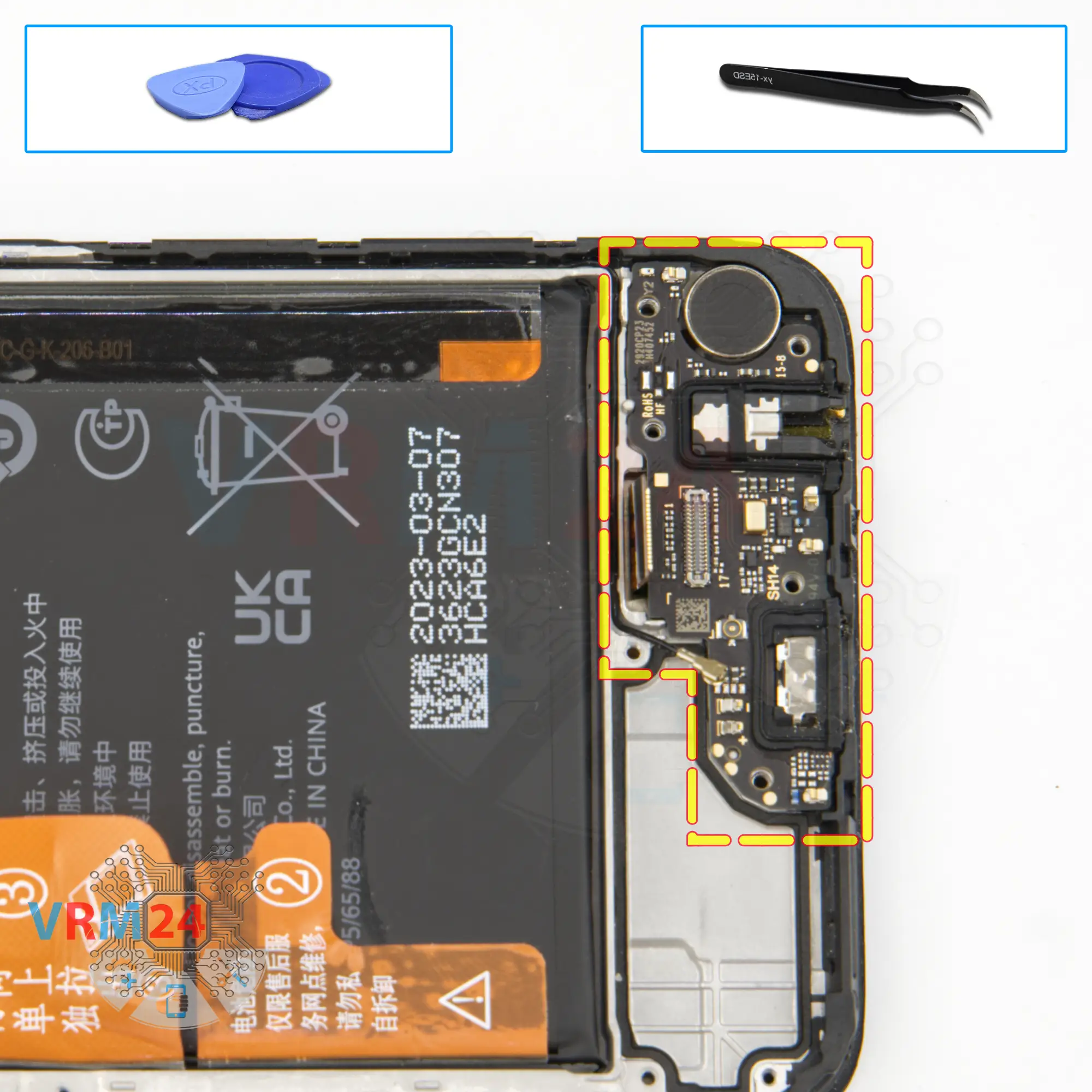
We move on to detaching the sub-board. Find the right place where we can gently pry, lift and remove the sub-board.
The sub-board has the charging port, microphone, headset jack port, and other elements on the back side.
Step 17.
Remove the cameras
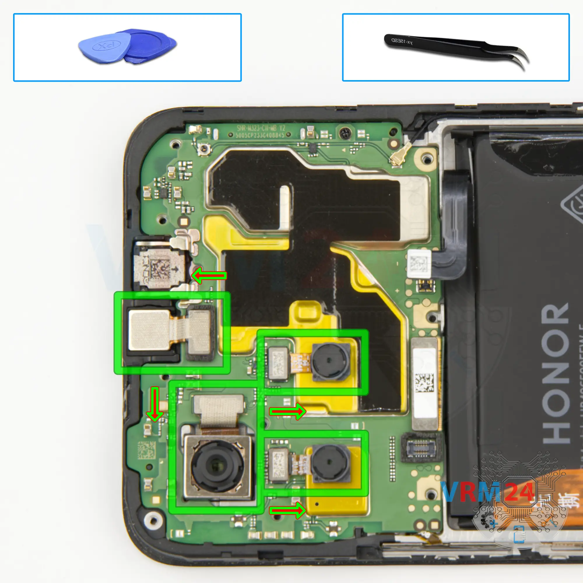
We move on to detaching the cameras on the main board.
First, we detach the rear cameras. Hold them slightly so that the cameras don't fall out and we don't damage them.
⚠️ The large rear camera may be glued to the display frame.
Next, we detach the front camera. We carefully remove the camera and put it aside.
Step 18.
Disconnect the connectors
We disconnect the connector of the cable to the display. We disconnect the coaxial cable connector.
Step 19.
Unscrew one screw
We need to remove one screw that holds the motherboard in place. For this we also use a one and a half millimeter Phillips screwdriver.
Step 20.
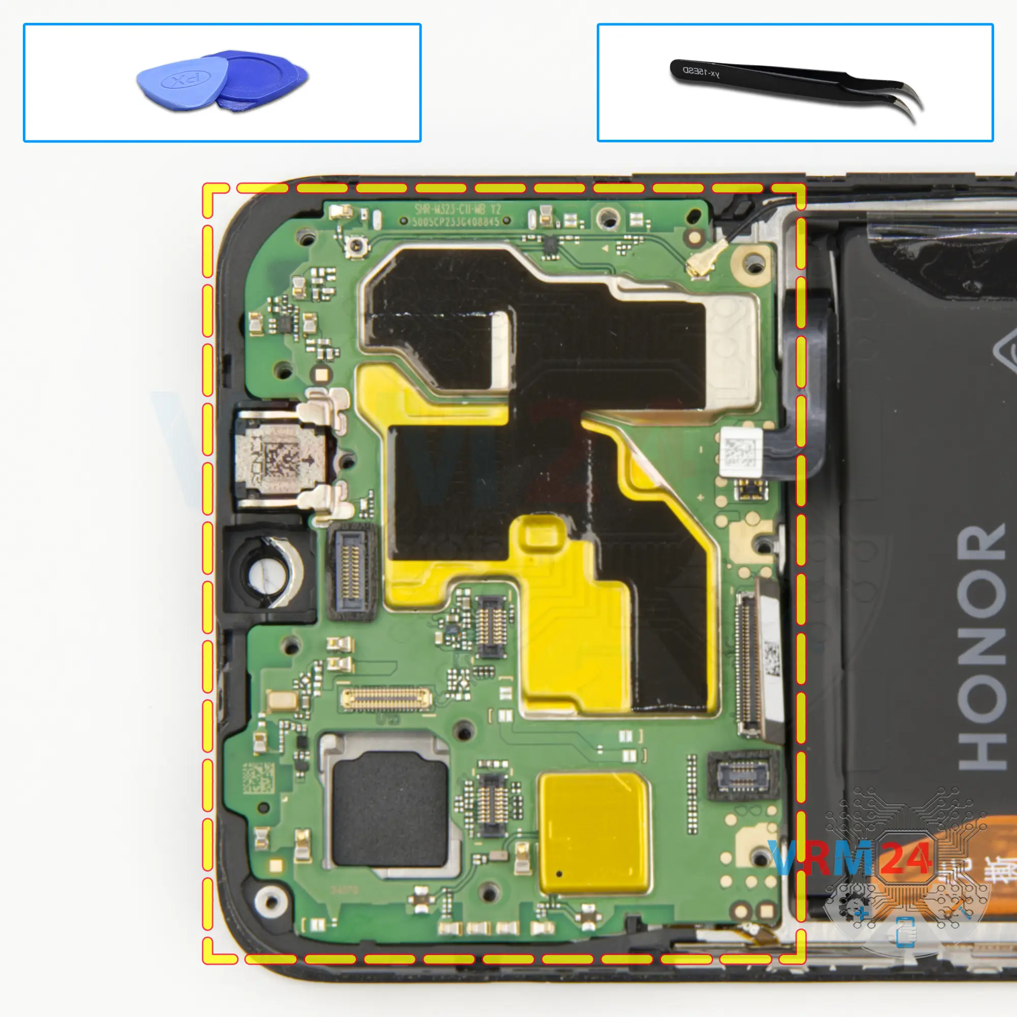
Remove the motherboard
Carefully remove the printed circuit board. There is no need to use a lever or try to reach the circuit board by force. Make sure that nothing is getting in the way or holding the circuit board.
The motherboard, also, may be attached with attachments like latches or hooks, be careful.
⚠️ Do not bend the circuit board when removing it or push tools under it. Unbeknownst to yourself, you can damage components or cables from the inside.
Step 21.
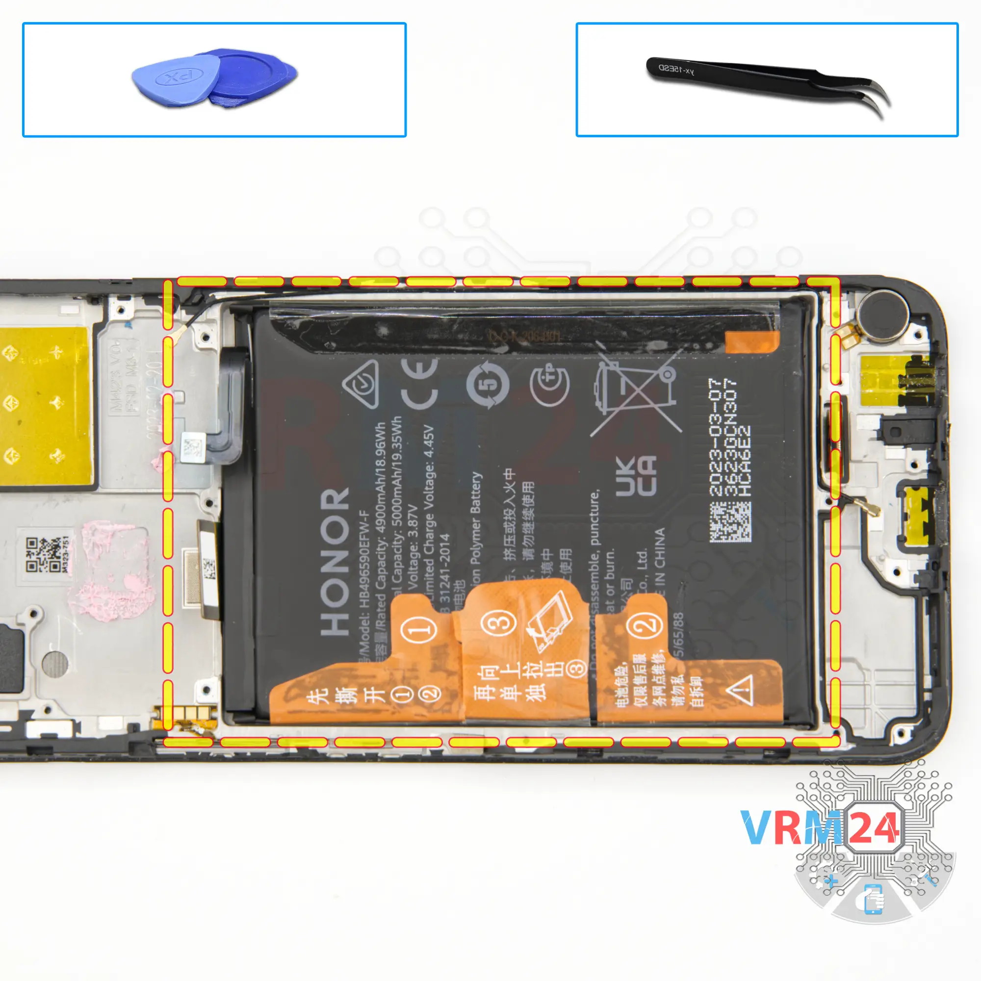
Remove the battery
And finally, we move on to detaching the battery, we have traditionally three brown tabs that need to be unwrapped. Then we need to read the description and do everything that is specified in the description.
And we unwrap the two tabs on the edges, which should be turned to the side as much as possible, and for the tab, which is located in the middle we need to gently pull up.
So, we carefully pull up the tab and remove the battery.
Under the battery we have a transparent coating that protects the display cable.
Step 22.
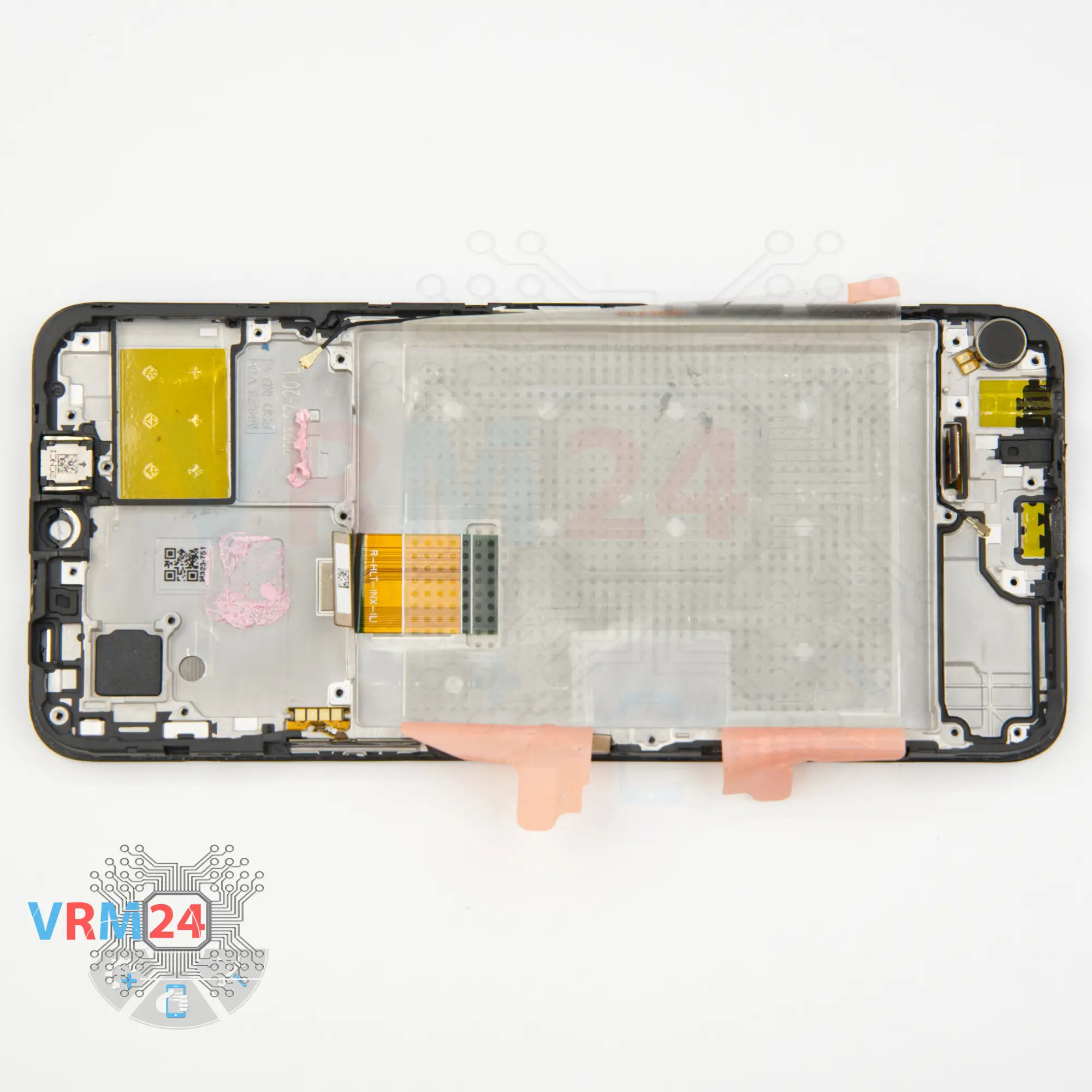
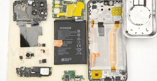
In the display frame remained
ℹ️ In the display frame remained: the earpiece speaker, vibration motor, coaxial cable and side buttons.

If you have a question, ask us, and we will try to answer in as much detail as possible. If this article was helpful for you, please rate it.

12065
Views
2
Likes
—
Share
1
Questions
Related Instructions
Related Reviews
Related Blog

Popular Questions

HONOR X8
Hello! I can't hear the other person only on speakerphone. Through the earpiece I can hear. Calls and YouTube are heard loudly. Please tell me, do I …
id269069571
J
Samsung Galaxy Tab S2 9.7'' SM-T819
Well I ordered all the things I needed from Amazon and got up the very first corner as shown in your video and now my screen is flashing lightning-li…
Jeanne Stumpf8
K
Lenovo K3 Note
can I exchange lenovo vibe k5 plus camera with lenovo k3 note camera..plzzz rply or make a video on this....or give me ur whatsapp no.to contacting y…
Kanha Kumar7
K
Alcatel OT POP 7 P310X
Hi... I am wondering if you can share a ROM back up of your tablet... I got bootloop on logo... thanks
Kevin Morales5
I
LG X Power K220
How to replace only the rear camera lens of the device?!
Iago Oliveira2Top instructions
Check our
Top Honor instructions most liked by readers
New instructions
Check our
New Honor brand instructions on vrm24.com