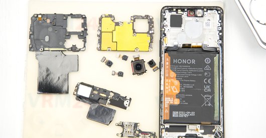

Recommended tools
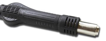
Heat gun
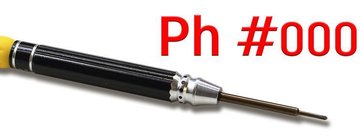
Screwdriver Phillips #000
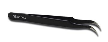
Tweezers
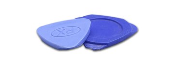
Non-metallic tool
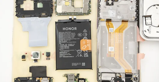
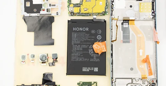
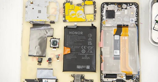
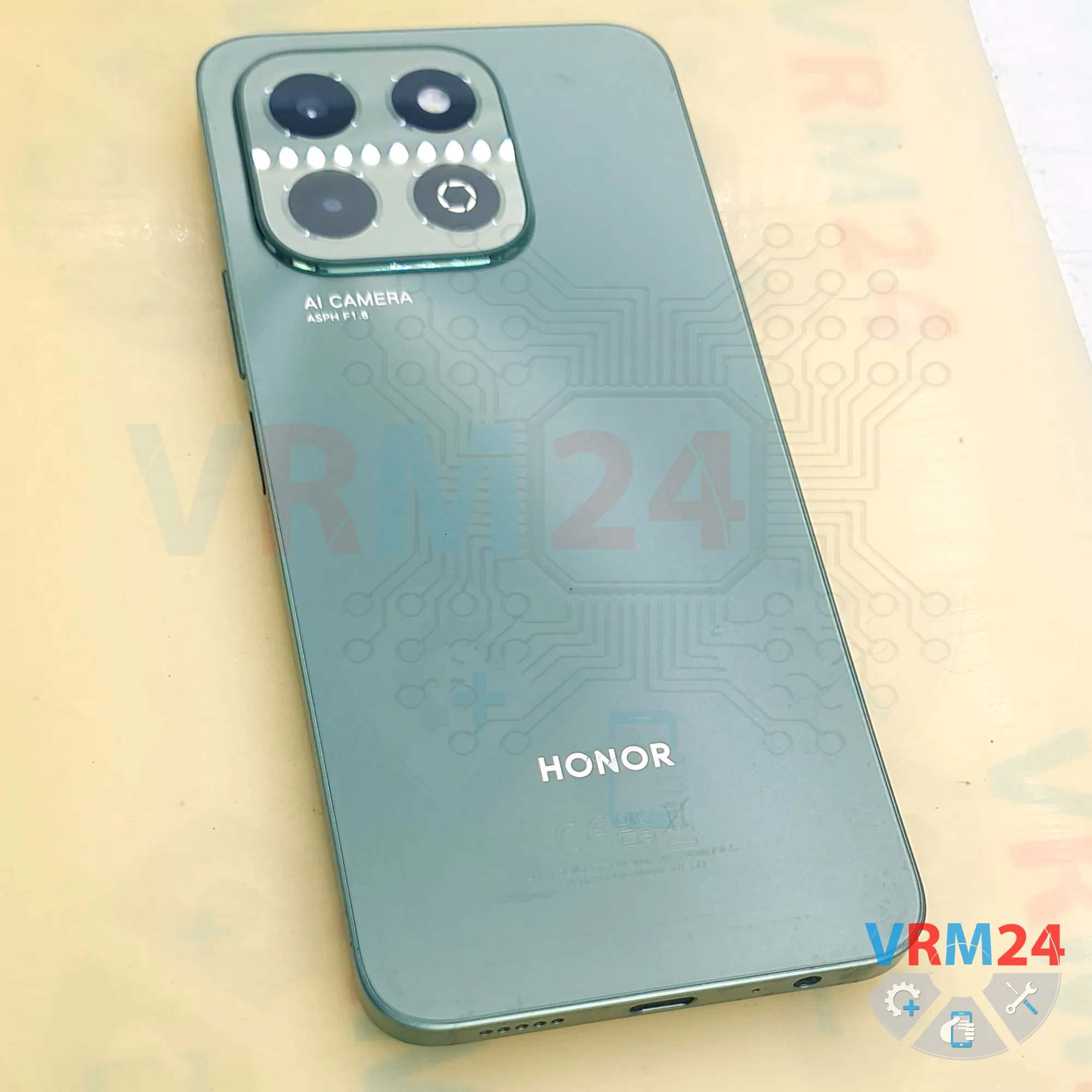
Disassembly/Repair of the mobile device Honor X6b (Honor X6b JDY-LX1) with each step description and the required set of tools.
38
Views
0
Likes
—
Share
0
Questions

Step 1.
Before disassembling!
⚠️ Before disassembling, do not forget to turn your phone off.
Step 2.
Remove the tray
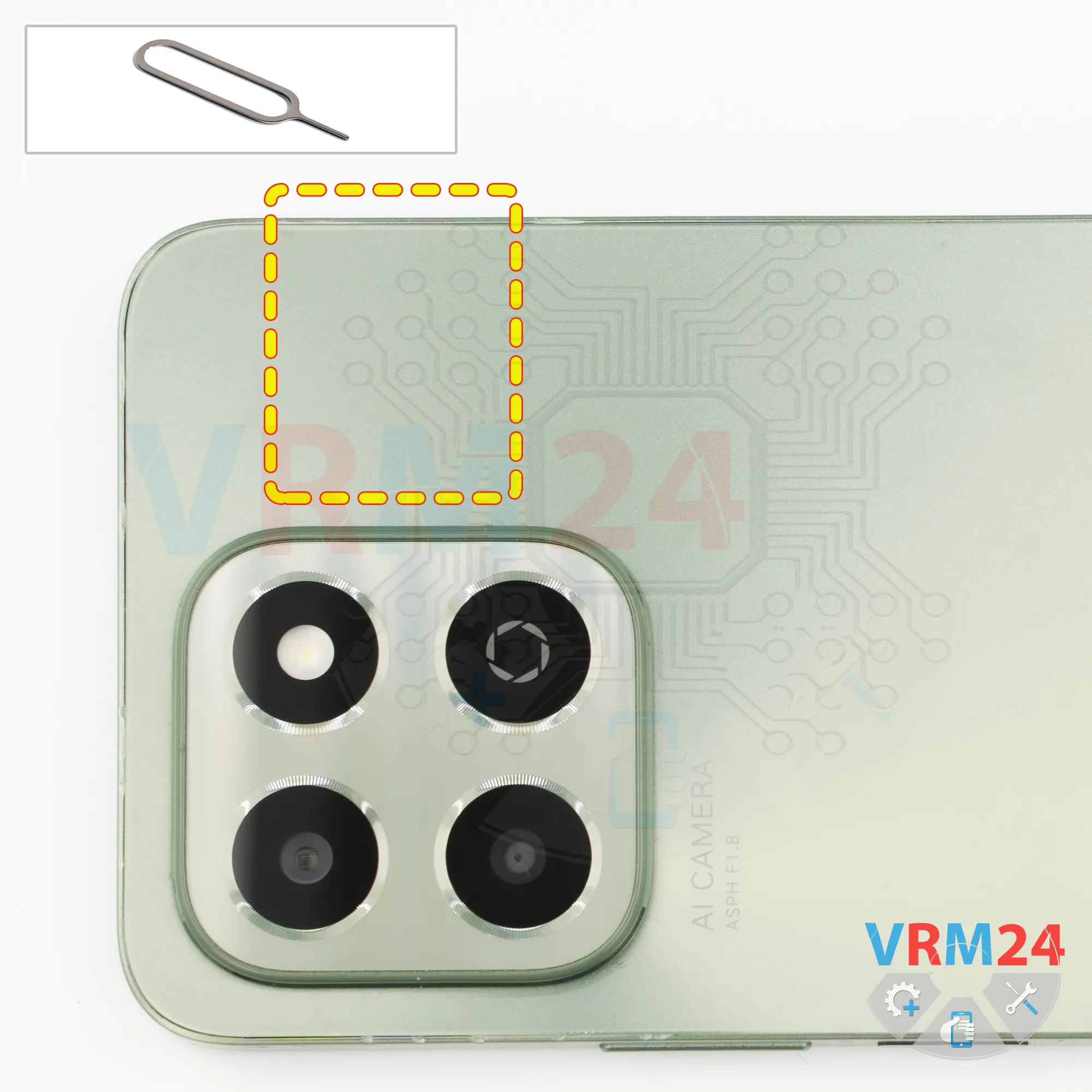
First, we need to remove the SIM card tray.
To do that, we use a SIM eject tool, insert it into the small hole, and pop the tray out. If the tray doesn't come out easily, we can also use tweezers to help pull it out.
Step 3.
Open the back cover
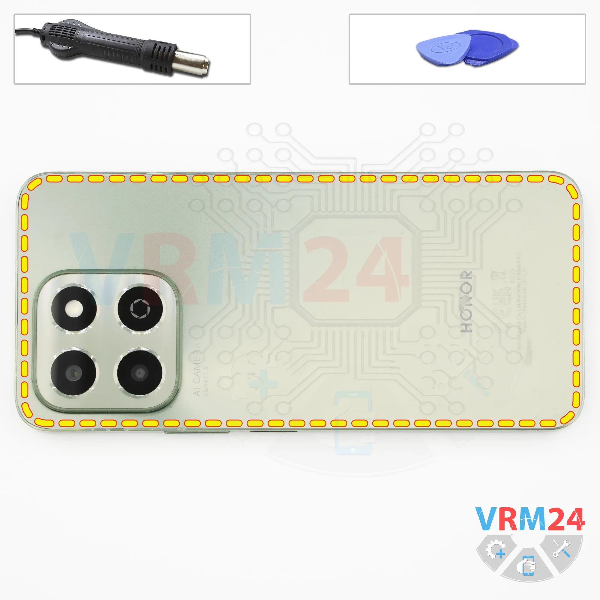
Next, we need to heat the surface of the back cover to approximately 70 degrees Celsius, or 160 degrees Fahrenheit. We're using a heating mat for this, but you can also use a heat gun or a hair dryer.
Keep in mind that there's additional adhesive around the cameras, so it's a good idea to heat that area as well.
Once that's done, we can start separating the back cover. We're using a thin plastic film for this.
Carefully insert it into the gap between the back cover and the midframe cover, then slide it along the edge to cut through the adhesive.
Don't push the film or any other tool too far inside. We don't know exactly what's underneath the back cover, and it's easy to accidentally damage flex cables, camera lenses, coaxial cables, and other components.
Notice that the back cover is thicker around the cameras. In this area, we can carefully press against the cover with our tool to lift it slightly and try to separate it.
Carefully lift the cover a little from the edge. Don't force the tool underneath it, as you might accidentally damage the cover. It's soft and flexible, but too much pressure or bending can still damage it.
We can also gently try to lift the cover and take a look at what's underneath, paying attention to where the cameras are located.
Carefully wiggle the cover back and forth, trying to lift it a little at a time, until we can finally separate it completely.
Step 4.
Unscrew the screws
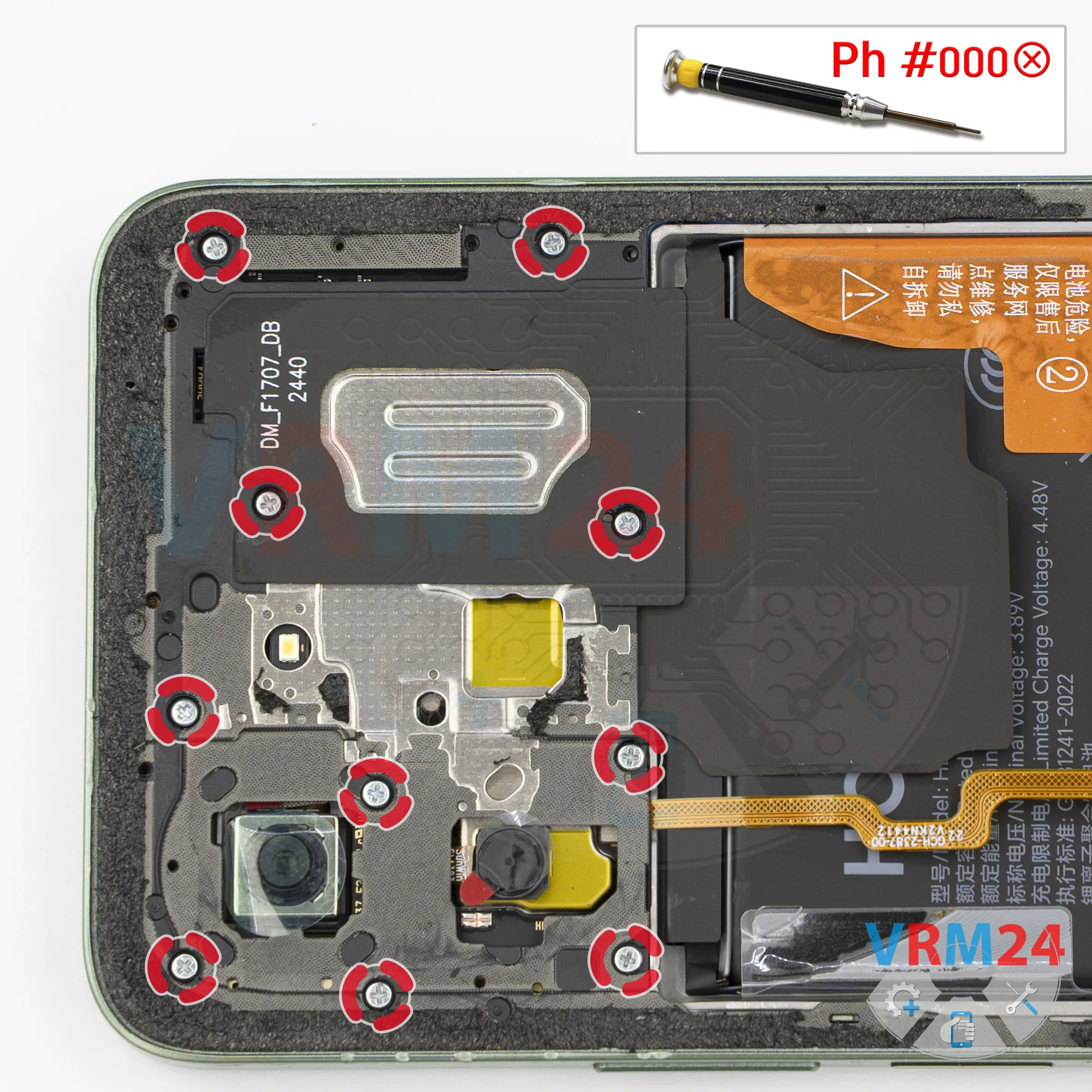
After that, we can start removing the screws. We're using a 1.5-millimeter Phillips screwdriver, or a Phillips #000.
It looks like all the screws are the same, but it's still better to arrange them in a specific order on a screw organizer mat.
Sometimes, screws don't fit properly if you put them back into different holes.
Step 5.
Unscrew the screws
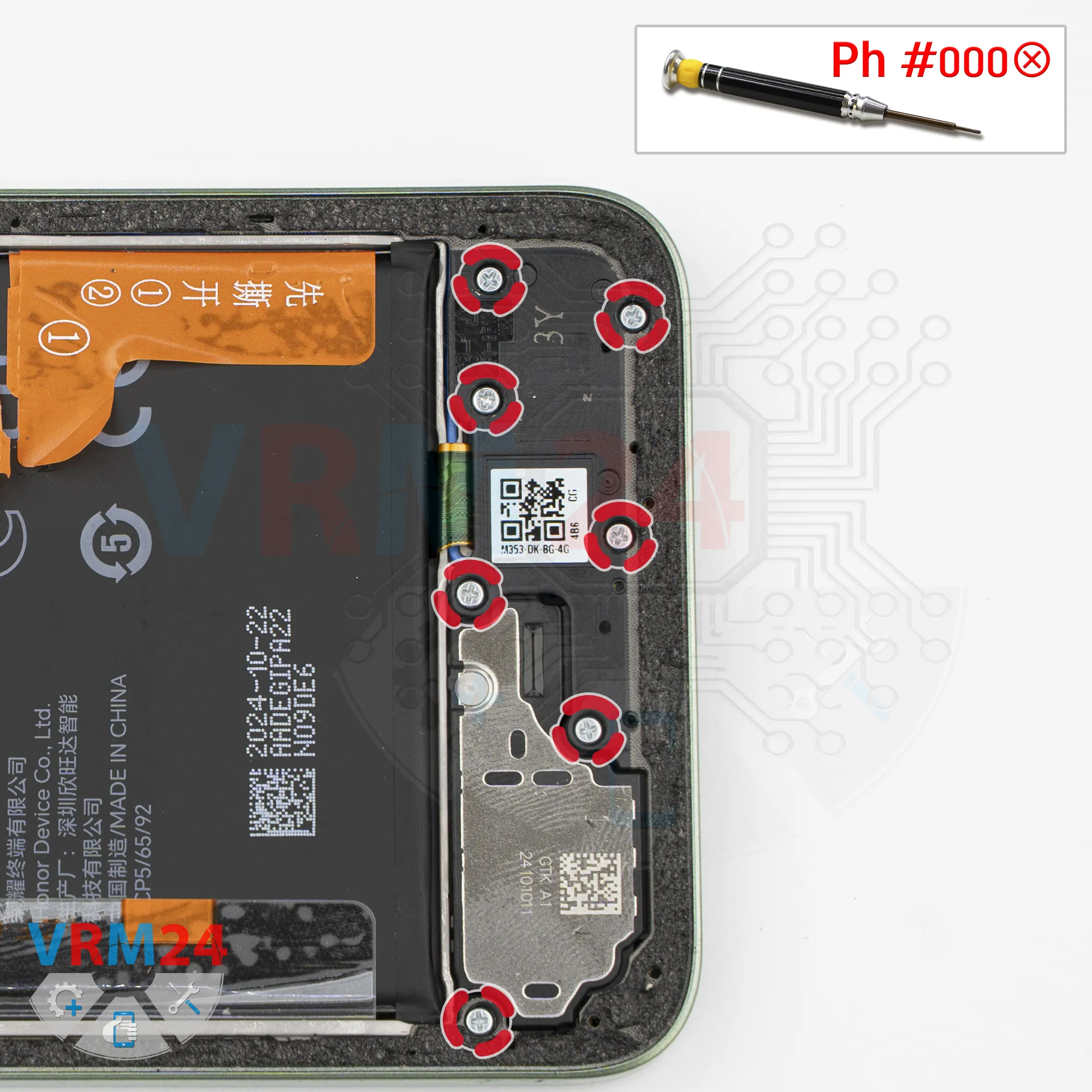
We also remove the screws at the bottom.
And, of course, it's best to keep the screws from the bottom section separate from those at the top.
Step 6.
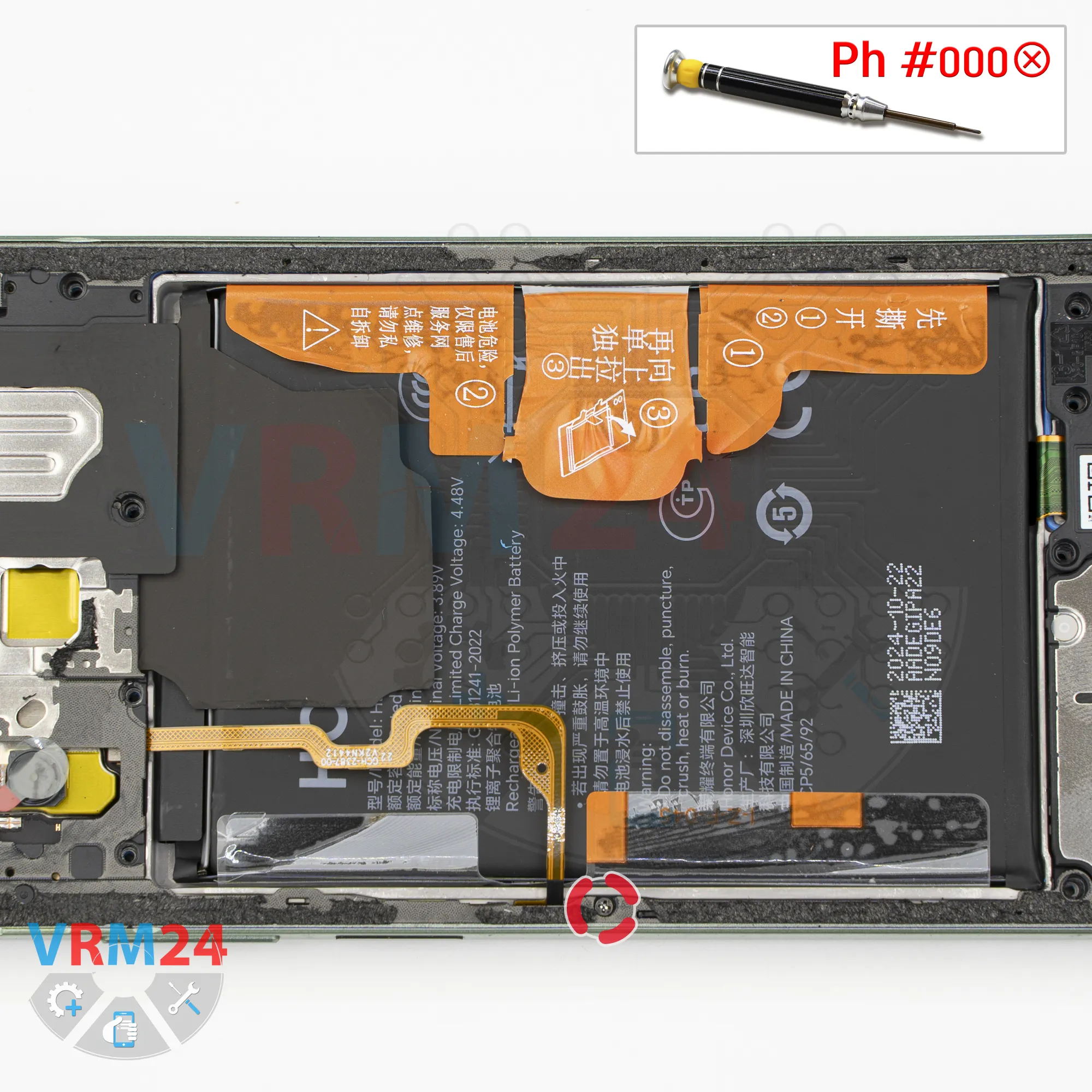
Unscrew one screw
Also, keep in mind that some midframe covers have additional screws in the center.
And, there's one more screw right in the middle, so we need to carefully remove it.
This screw is different from the others. It's smaller, so we'll keep it separate.
Step 7.
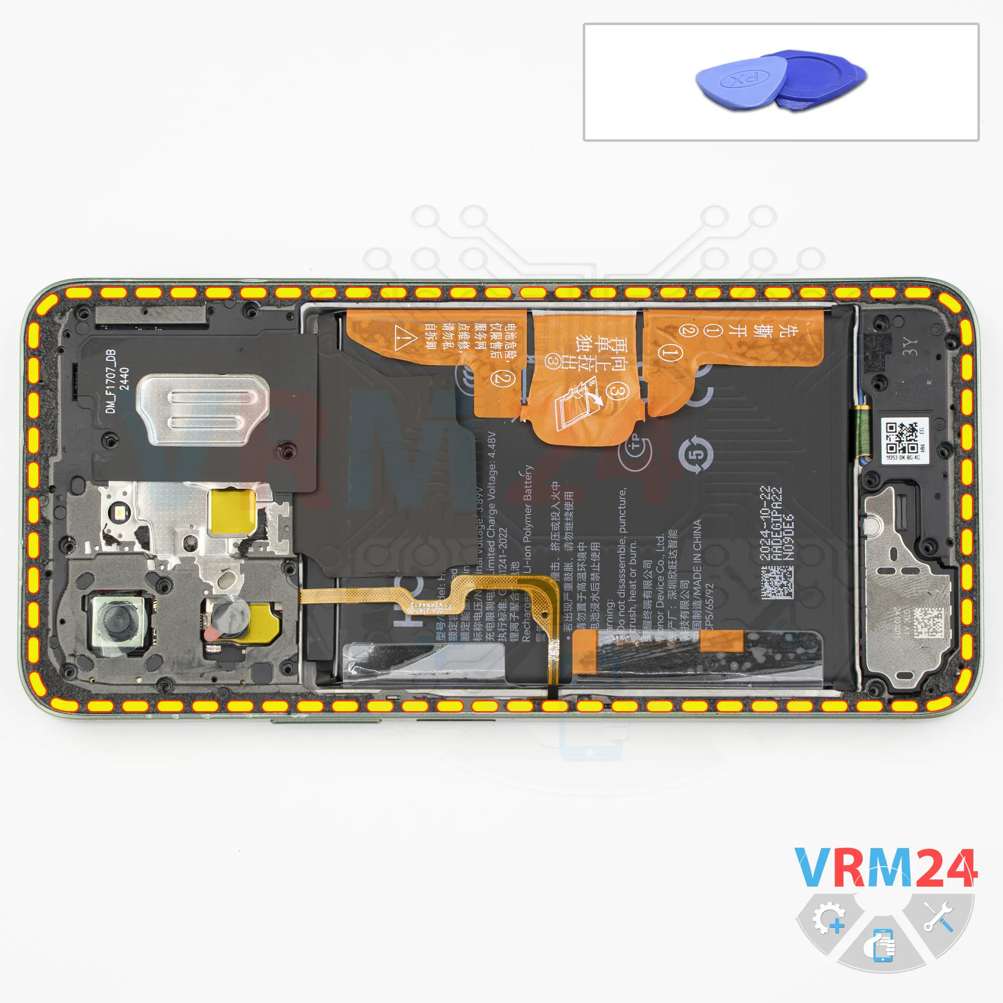
Open the mid-frame
Once we've removed the screws, we need to detach the midframe cover.
We're using a thin plastic film again. Insert it into the gap between the midframe cover and the display frame, near the SIM card tray opening.
Release a few clips, and then switch to a thicker opening tool.
As always, be especially careful around the corners, where the cover is held very tightly in place. Also, be careful near the SIM card tray opening, because the cover is quite thin there and can easily be damaged.
And, of course, we need to be very careful around the fingerprint sensor so we don't accidentally damage its flex cable.
Step 8.
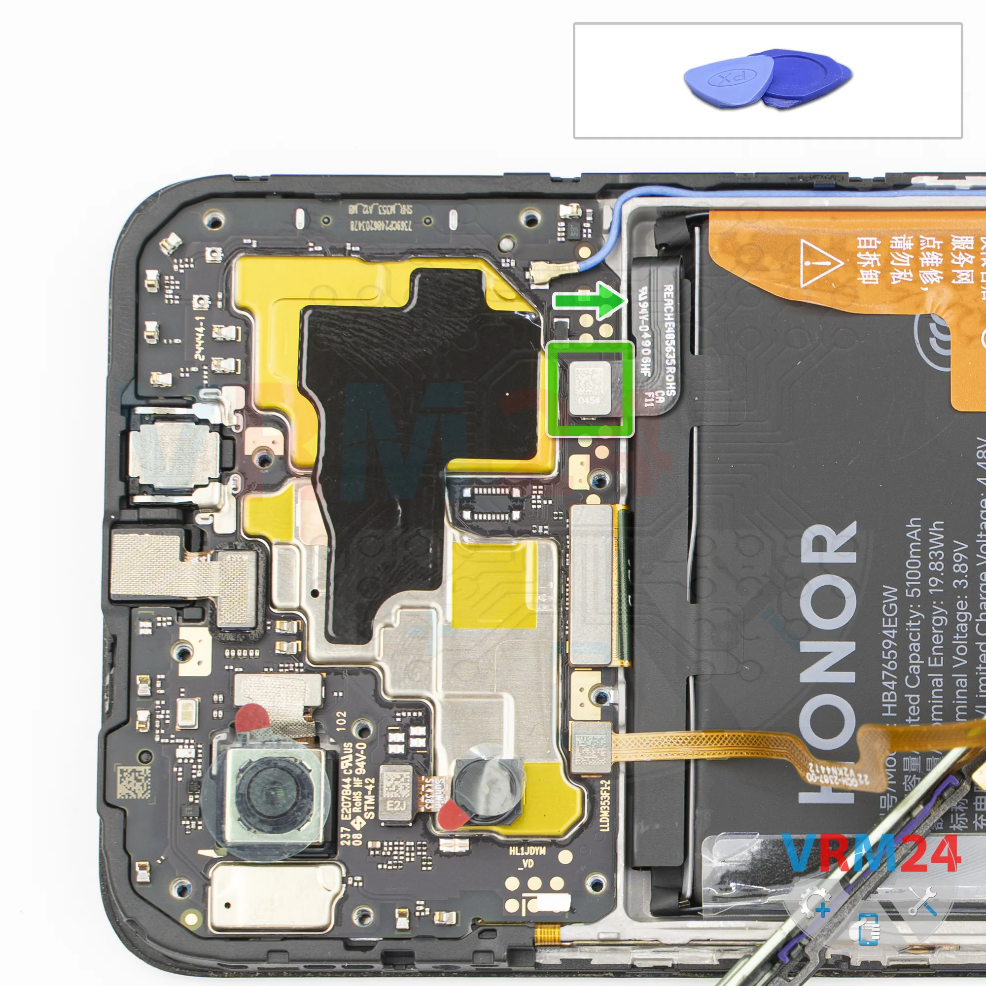
Disconnect the battery connector
Next, disconnect the battery connector, again using a non-metallic tool.
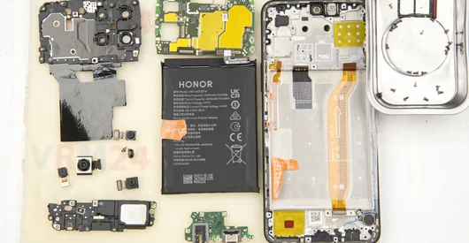
ℹ️ The Honor X6b JDY-LX1 uses a HB476594EGW rechargeable battery with a capacity of 5100 mAh.
Step 9.
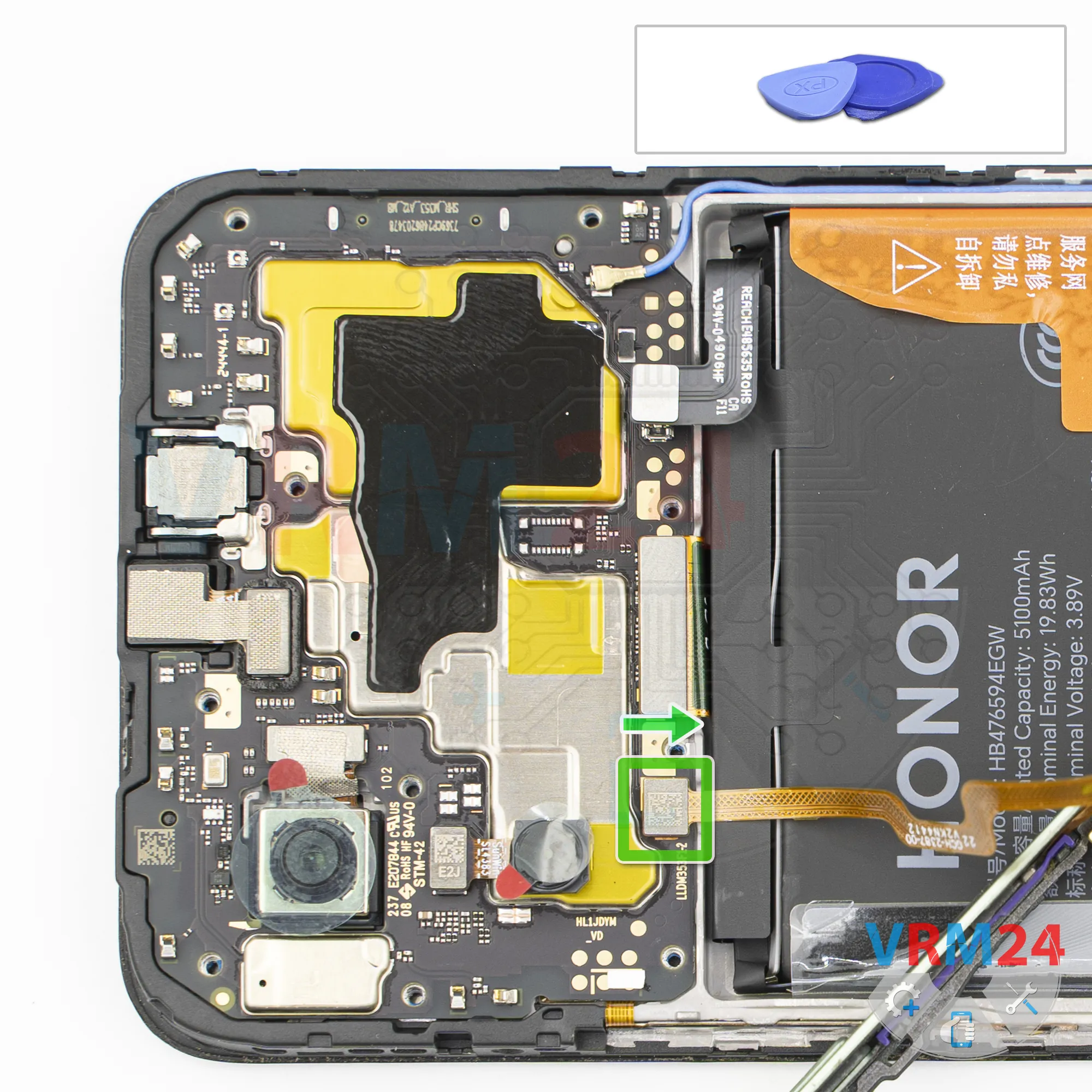
Disconnect the connector
Now there's nothing preventing us from removing the midframe cover.
Carefully flip it over and use a non-metallic tool to disconnect the fingerprint sensor connector.
As you can see, it has antenna contact pads and antenna traces.
Step 10.
Unscrew one screw
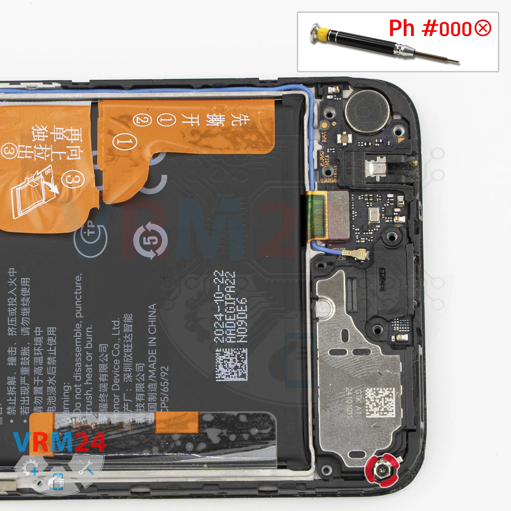
At the bottom, one of the screws holds the loudspeaker cover in place.
Step 11.
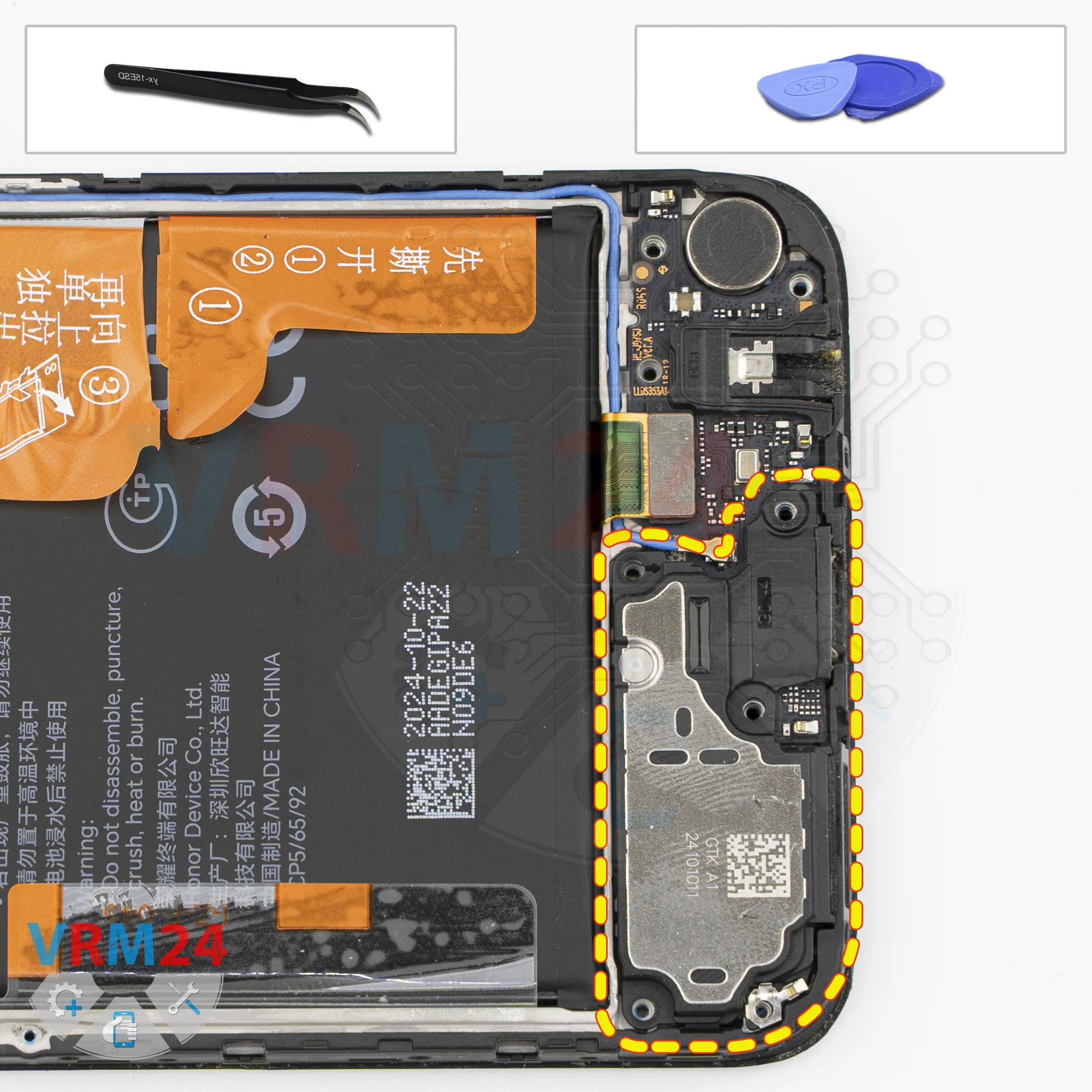
Remove the loudspeaker
Now, let's try to remove the loudspeaker cover.
Carefully find the right spot to get underneath it with the tool, lift it up, and set it aside.
Step 12.
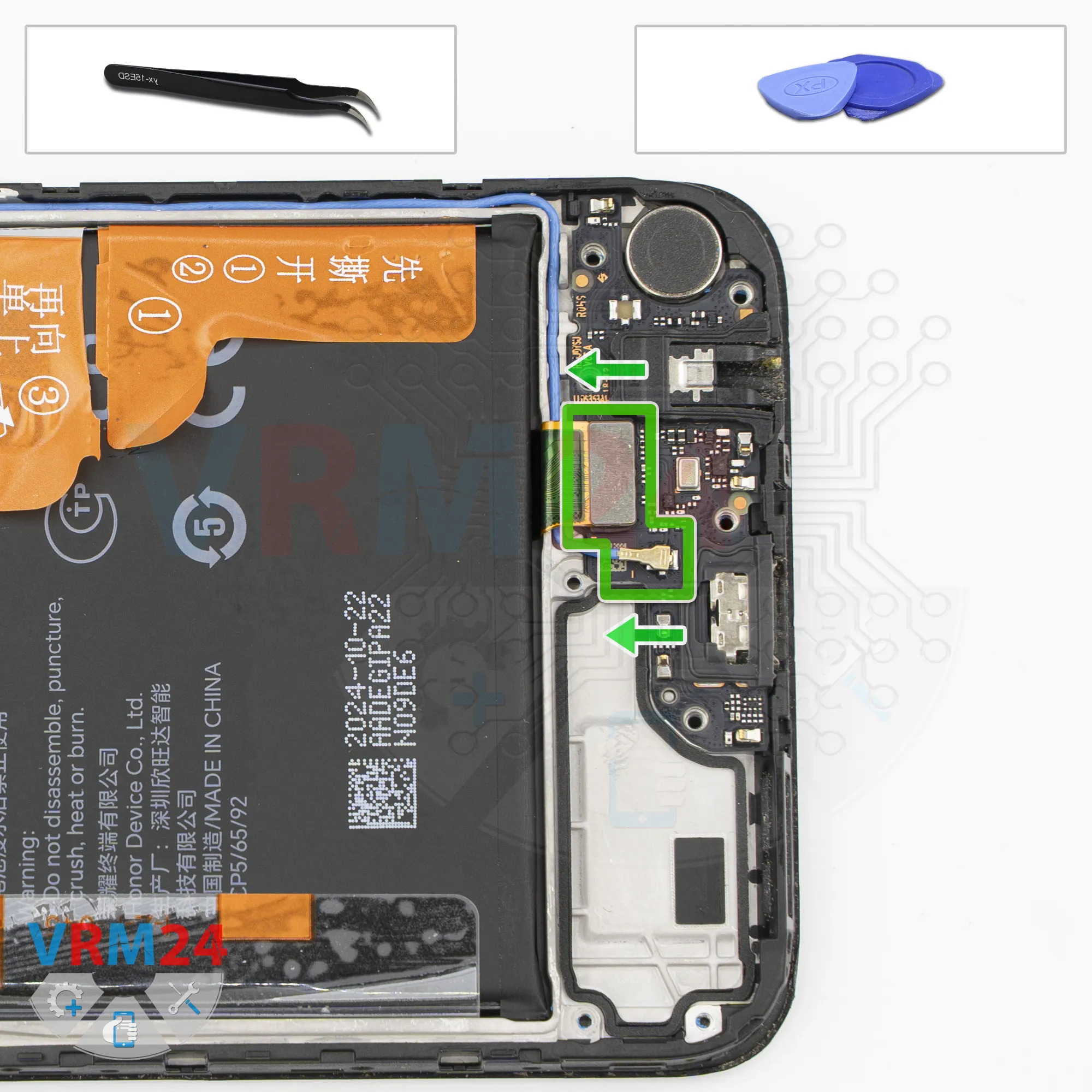
Disconnect the connector
After that, disconnect the connectors: first, the interconnect flex cable connector, and then the coaxial cable connector.
Step 13.
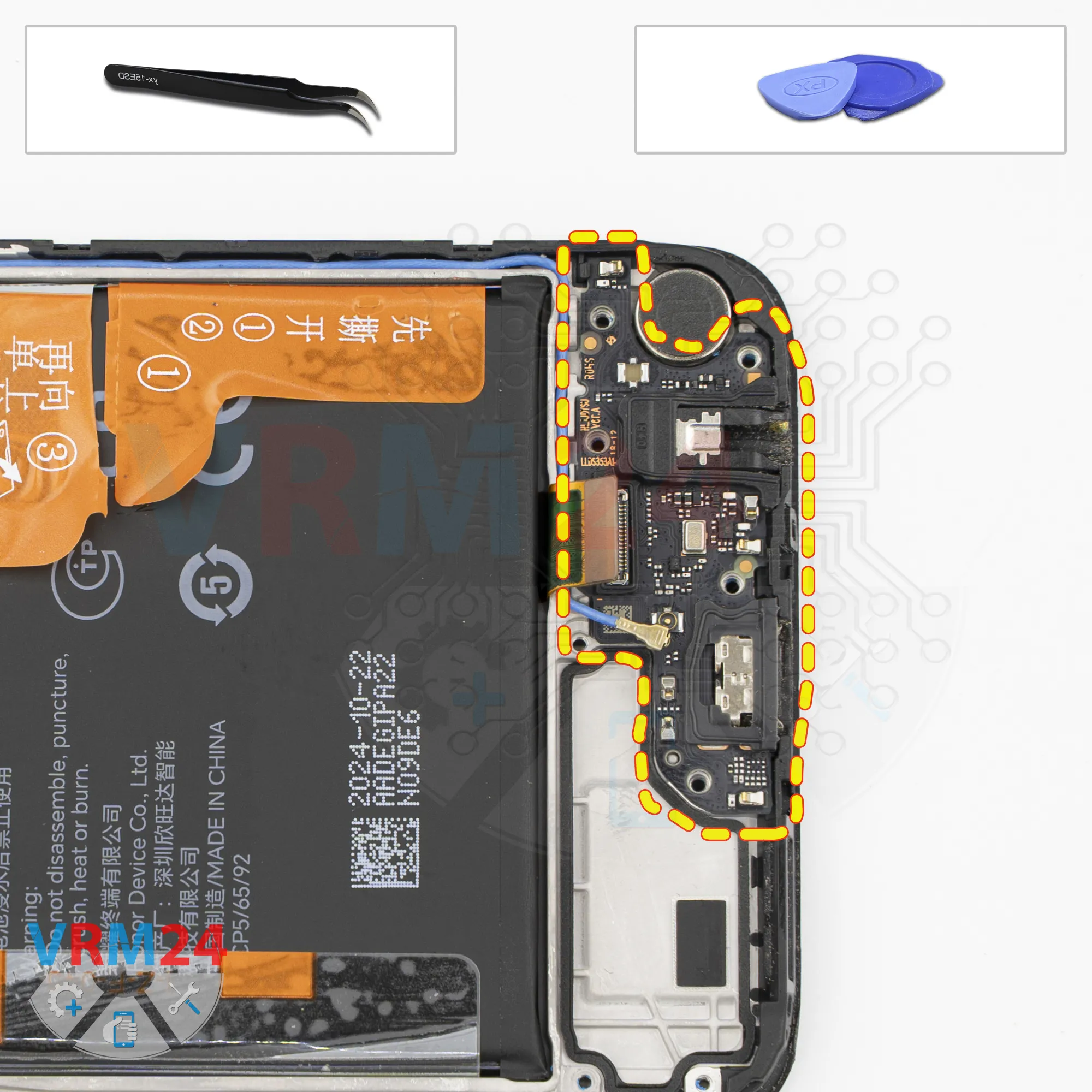
Remove the sub-board
Now we can remove the sub-board.
Again, we need to find the right spot to carefully get underneath the board, lift it up, and take it out.
As we can see, the sub-board has the charging port, microphone, headphone jack port, and several other components on the back.
The vibration motor remains inside the display frame.
Step 14.
Disconnect the connectors
Next, disconnect one connector for interconnect flex cable and the display flex cable, and the coaxial cable connector.
Step 15.
Remove the cameras
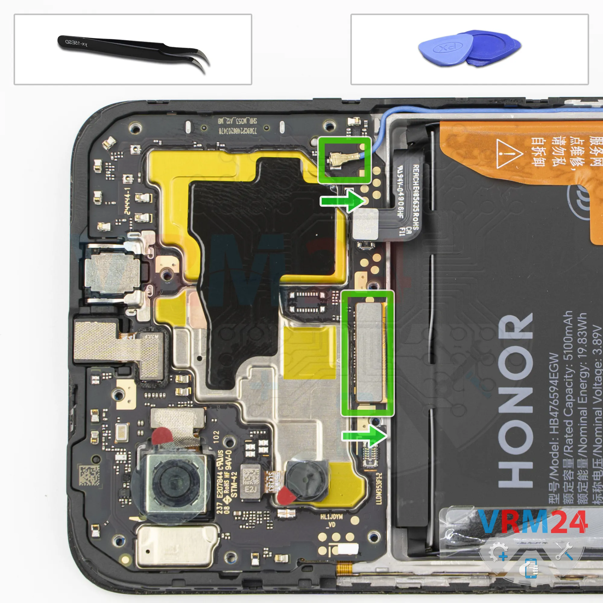
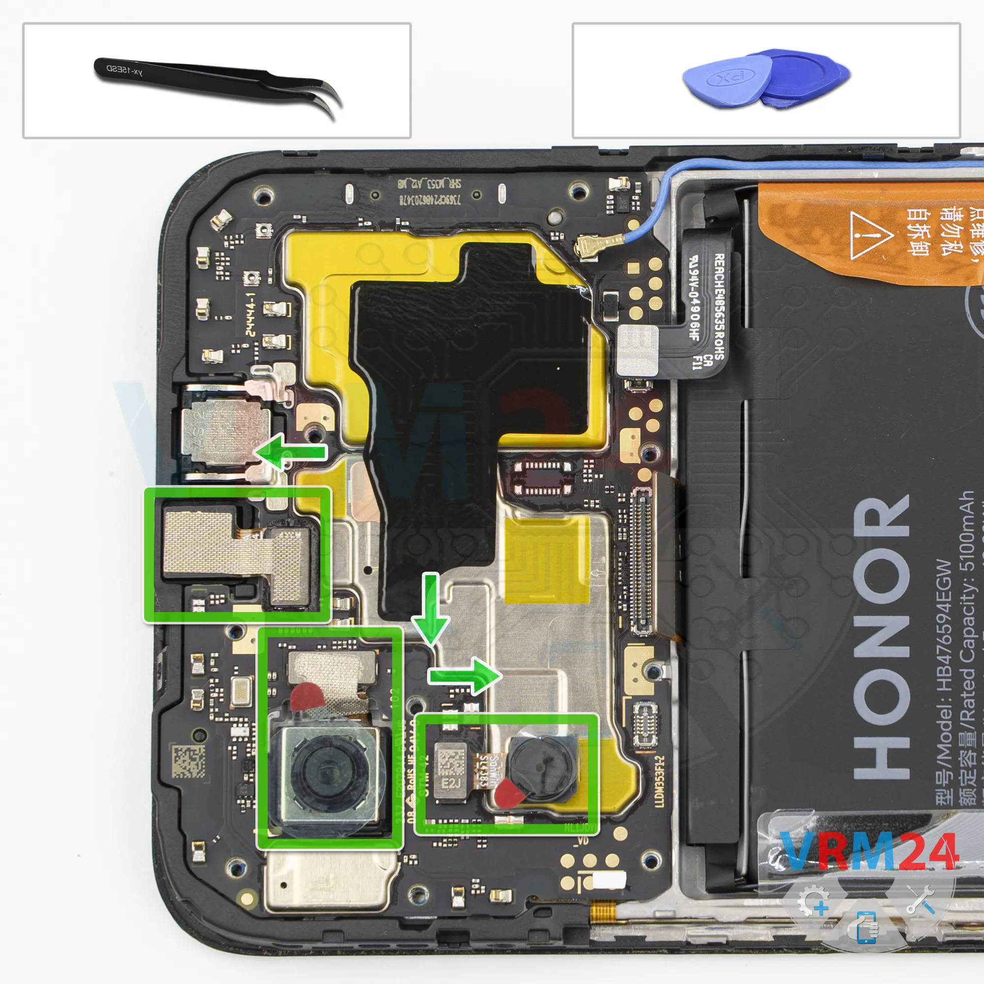
Now, we disconnect the cameras. Carefully get underneath the connectors, lift them up, and remove the cameras.
We can also remove the front-facing camera. Carefully get underneath it and lift it out.
It's best to cover the front camera lens to keep dust and debris from getting onto it. Then, set the camera aside.
Step 16.
Remove the motherboard
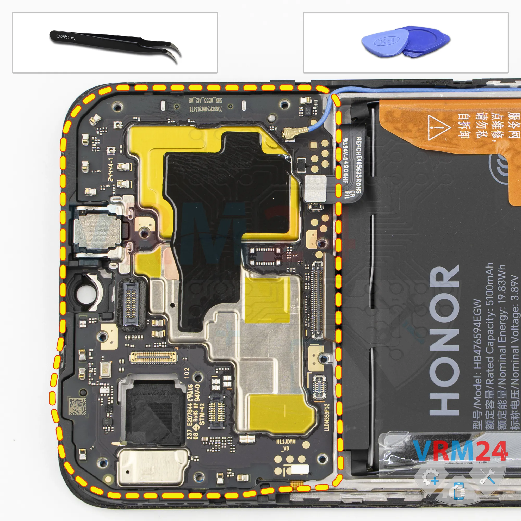
Next, check to make sure there are no screws left.
Now there's nothing holding the motherboard in place, so we can remove it.
Carefully find the right spot to get underneath the board, lift it up, and take it out.
Keep in mind that the motherboard may be held in place by thermal paste on the back.
Step 17.
Remove the battery
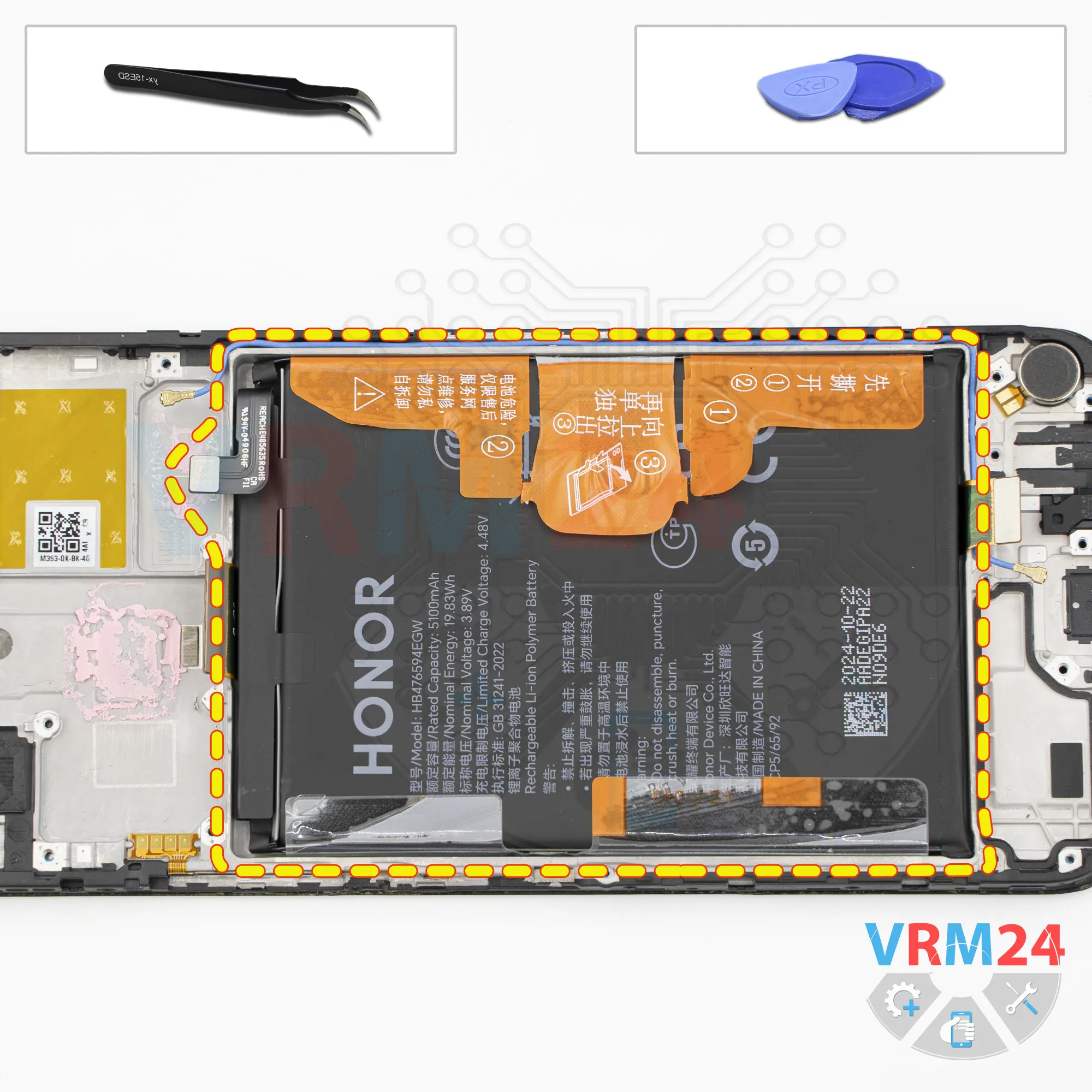
Finally, let's move on to removing the battery.
We gently peel tabs back. Then, pull the middle tab upward and carefully remove the battery.
Underneath the battery, there's a transparent adhesive protective layer that protects the interconnect flex cables.

If you have a question, ask us, and we will try to answer in as much detail as possible. If this article was helpful for you, please rate it.

38
Views
0
Likes
—
Share
0
Questions
Related Instructions
Related Reviews
Related Blog
Popular Questions

HONOR X8
Hello! I can't hear the other person only on speakerphone. Through the earpiece I can hear. Calls and YouTube are heard loudly. Please tell me, do I …
id269069571
T
Xiaomi RedMi 3
HI, is it possible to use this battery to another xiami phone mi5s ?
tamisra tamisra14
Oppo A9 (2020)
where is wifi ic on oppo f11
d33p
C
Lenovo Vibe X2
how to put that silver part (back of the phone) back? thanks :D
cunga lunga6
R
Xiaomi RedMi Note 3
I Have a xiaomi redmi note3 pro special edition, but when using wifi internet it overheating and battery draining so fast. after full charge with nor…
rizwan Md.1Top instructions
Check our
Top Honor instructions most liked by readers
New instructions
Check our
New Honor brand instructions on vrm24.com