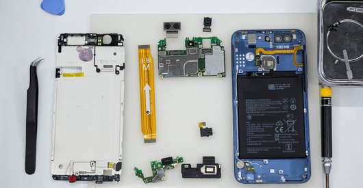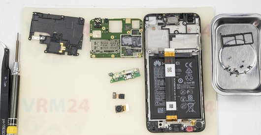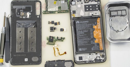


Recommended tools
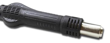
Heat gun
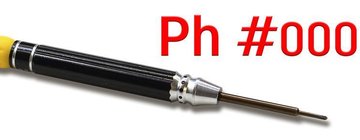
Screwdriver Phillips #000
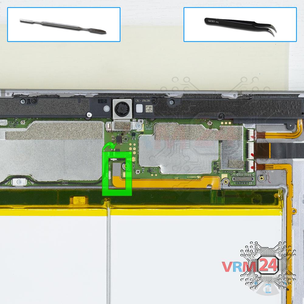
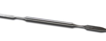
Opening tool / Spudger
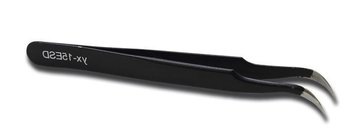
Tweezers
Disassembly/Repair of the mobile device Huawei MediaPad M3 Lite 10'' (Huawei MediaPad M3 Lite 10'' (BAH-L09)) with each step description and the required set of tools.
18510
Views
2
Likes
—
Share
19
Questions

Step 1.
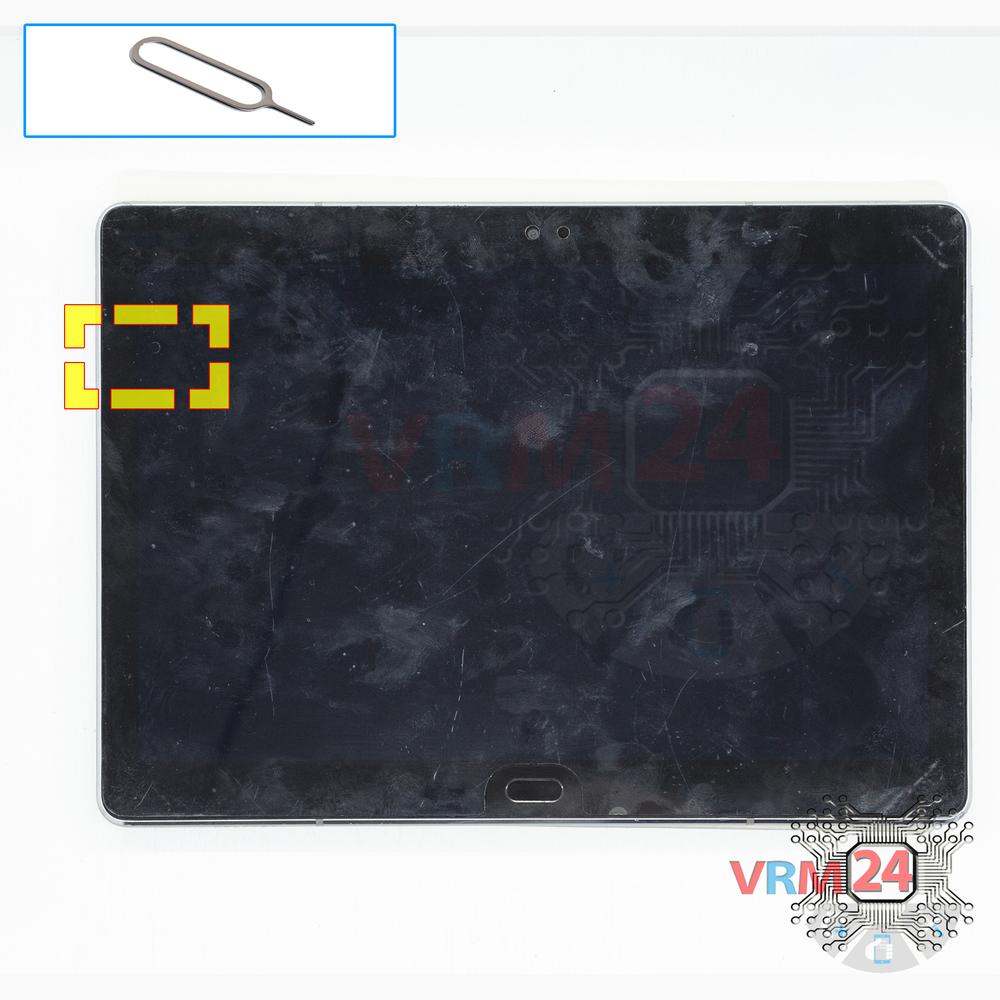
Remove the trays
Using the key tool, open the SIM and Micro SD cards tray and remove it.
⚠ Warning!
Do not push too hard this may cause damage.
Step 2.
Open the display module
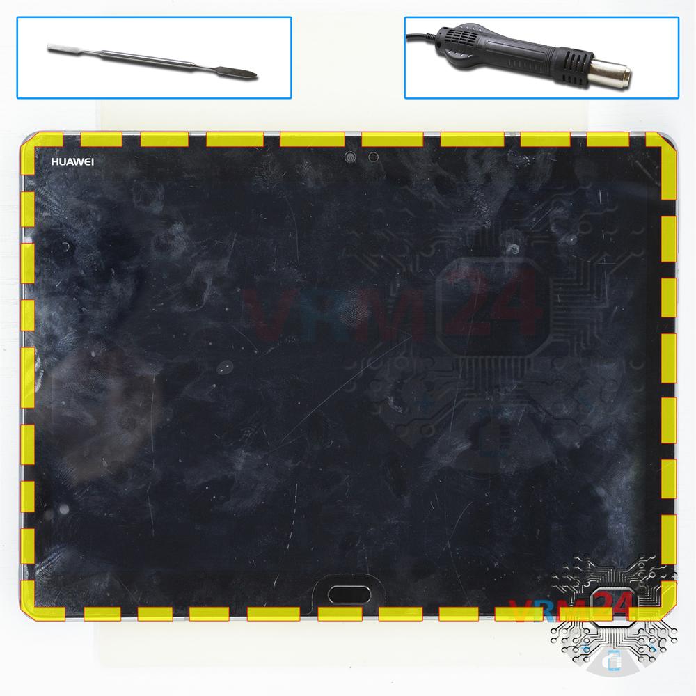
Separate the display module and turn it over.
⚠ Warning!
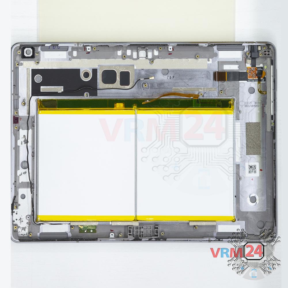
For careful separation, we recommend using a heat gun. At the same time, it is necessary to heat carefully in order, not to damage the surface of the device.
Step 3.
Remove the bracket
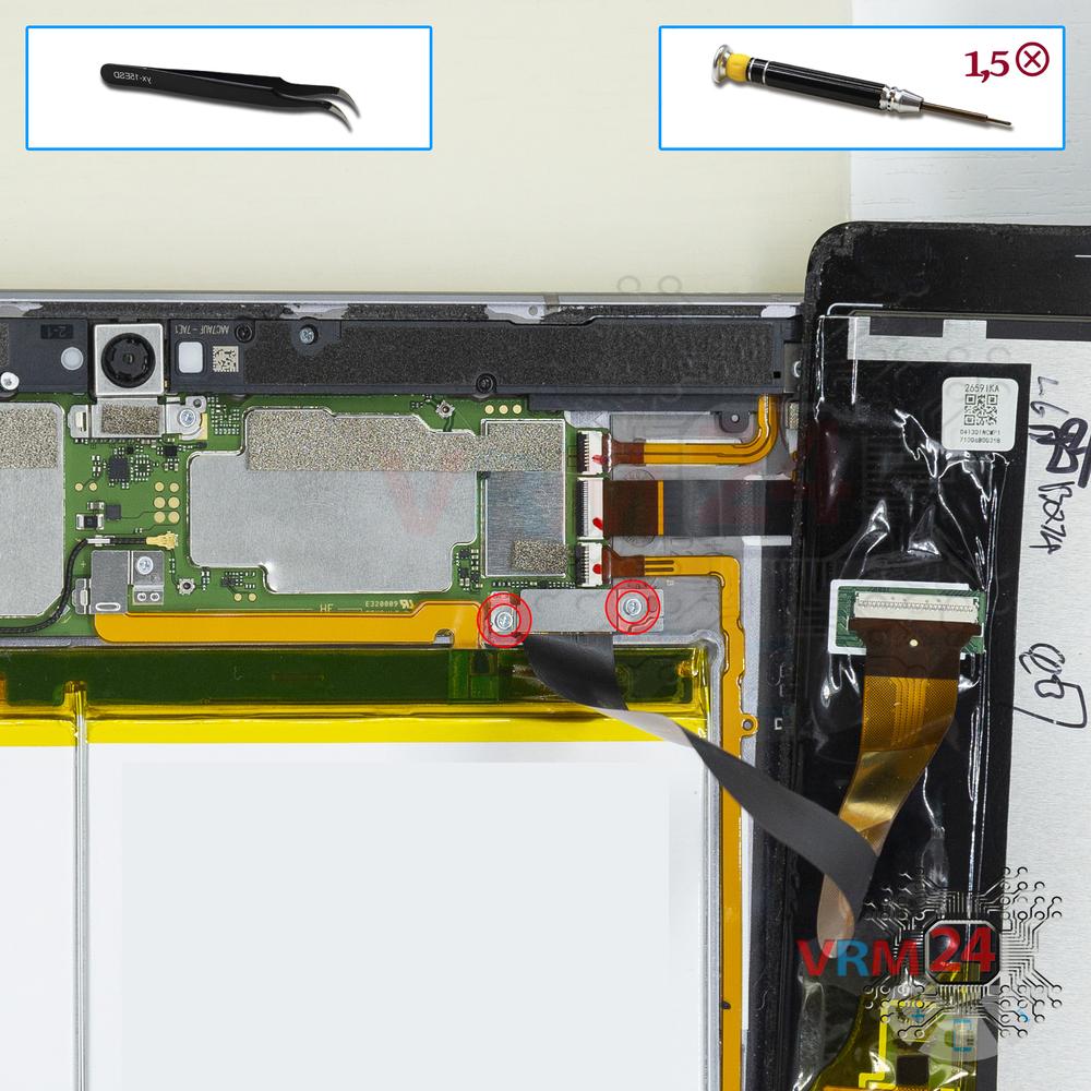
Using a screwdriver (Phillips 1.5 mm PH000), unscrew 2 screws and remove the bracket holding the connectors.
Step 4.
Open the display module
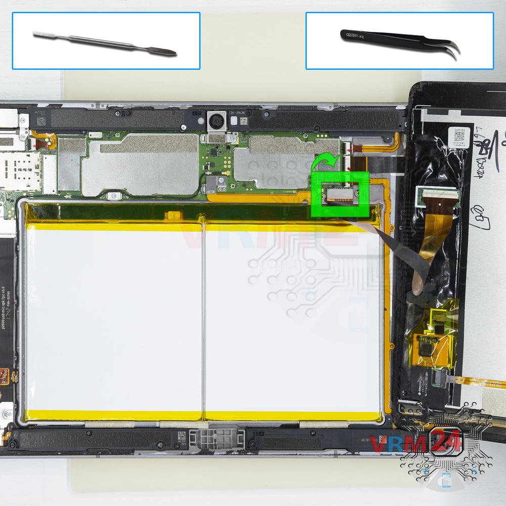
Pry up the connector and remove the display module.
Step 5.
Unscrew one screw
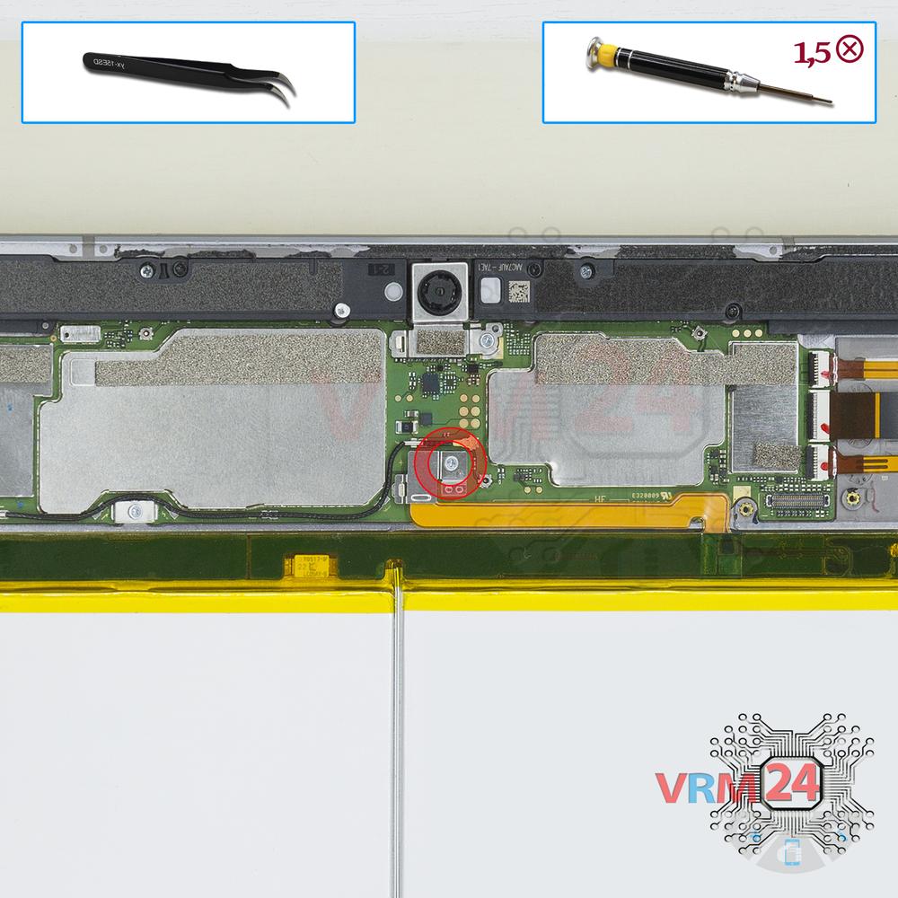
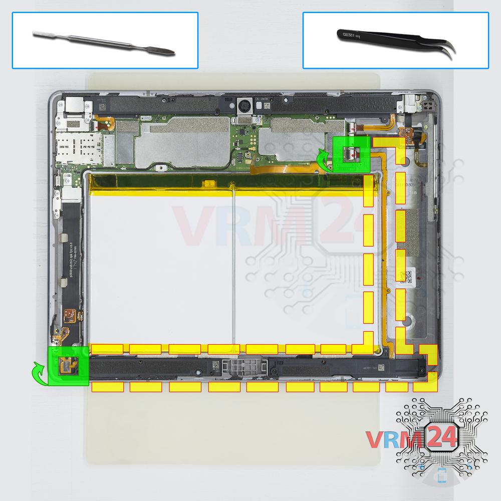
Using a screwdriver (Phillips 1.5 mm PH000), unscrew 1 screw and remove the bracket holding the battery connector.
Step 6.
Disconnect the battery connector
Disconnect the battery connector. The battery model of Huawei MediaPad M3 Lite is HB26A5I0EBC.
⚠ Warning!
We strongly recommend disconnecting the connector to avoid a possible short circuit during disassembly.
Step 7.
Unscrew the screws
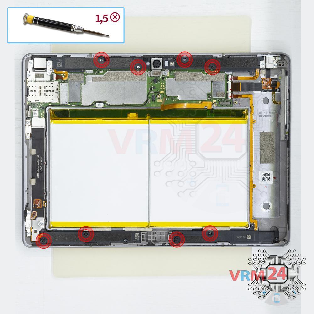
Using a screwdriver (Phillips 1.5 mm PH000), unscrew 8 screws.
Step 8.
Unscrew one screw
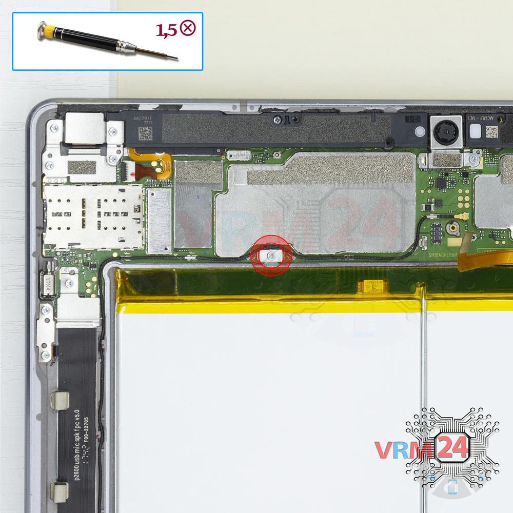
Using a screwdriver (Phillips 1.5 mm PH000), unscrew 1 screw.
Step 9.
Unscrew the screws
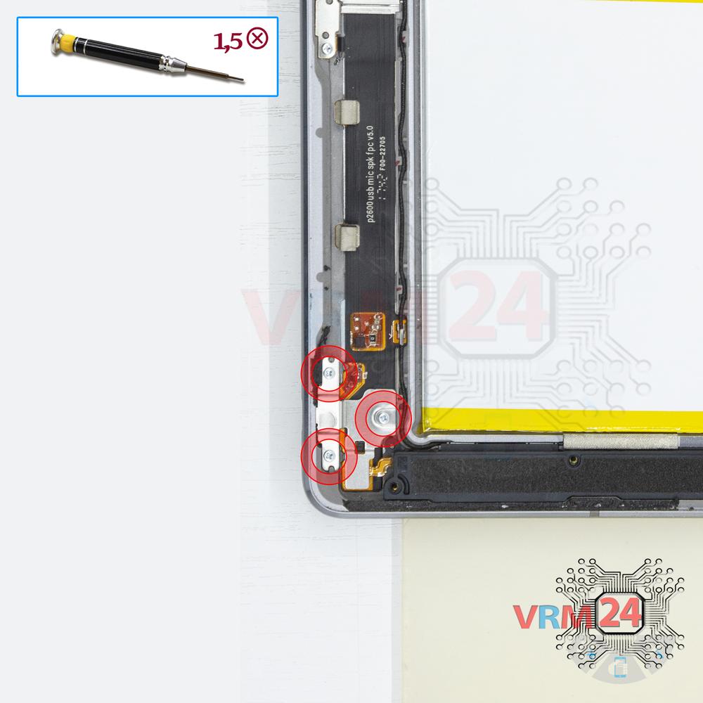
Using a screwdriver (Phillips 1.5 mm PH000), unscrew 3 screws.
Step 10.
Remove the bracket
Remove the bracket.
Step 11.
Remove the loudspeaker
Pry the connectors and remove the two buzzers (loudspeakers) assemblies.
Step 12.
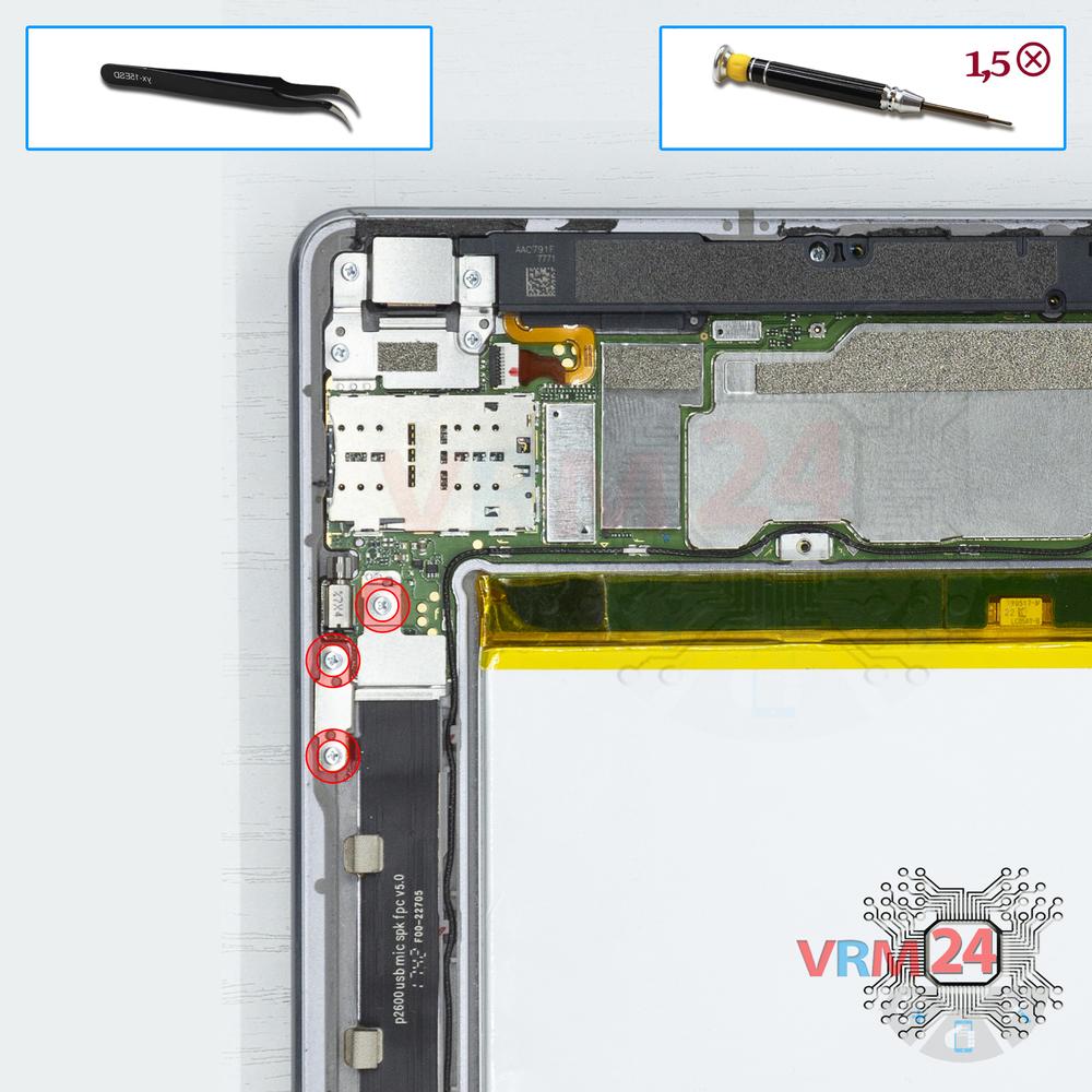
Remove the bracket
Using a screwdriver (Phillips 1.5 mm PH000), unscrew 3 screws and remove the bracket holding the connectors.
Step 13.
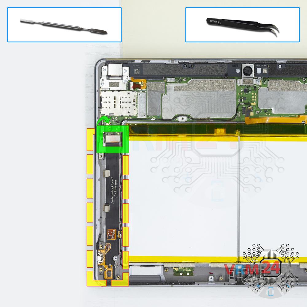
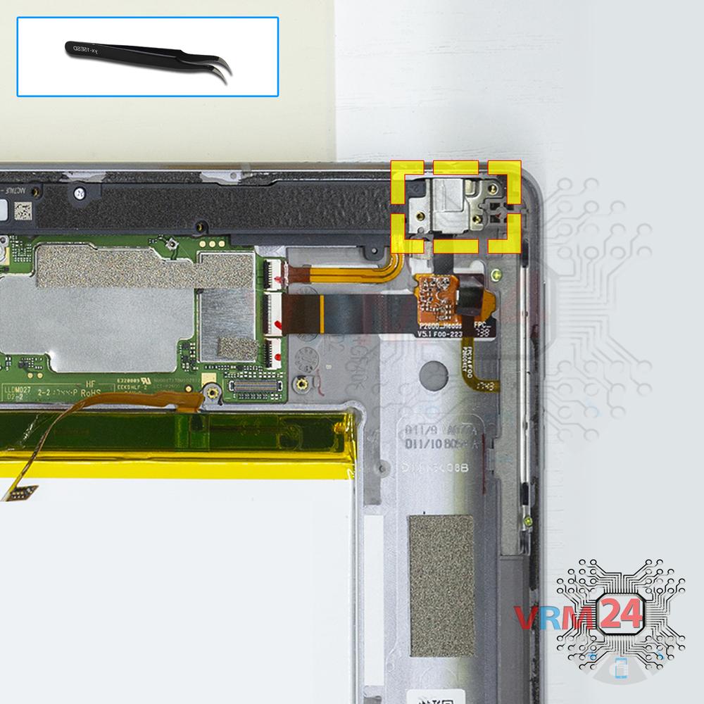
Remove the charging port
Disconnect the connector and remove the cable with a charging port.
Step 14.
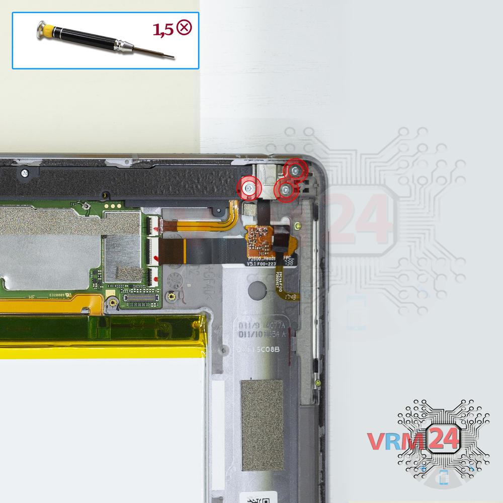
Remove the bracket
Using a screwdriver (Phillips 1.5 mm PH000), unscrew 3 screws and remove the bracket holding the connectors.
Step 15.
Remove the bracket
Remove the bracket.
Step 16.
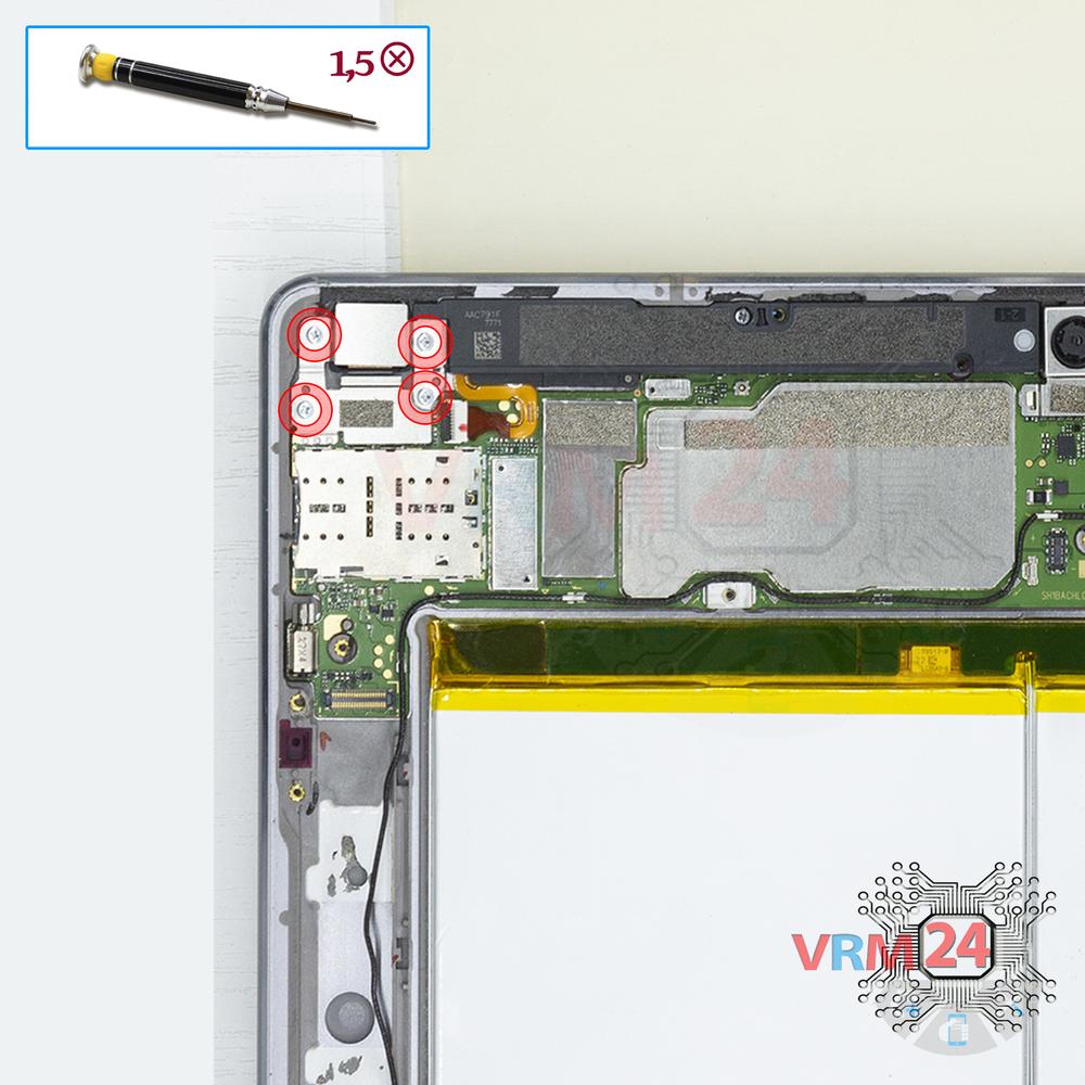
Unscrew the screws
Using a screwdriver (Phillips 1.5 mm PH000), unscrew 4 screws.
Step 17.
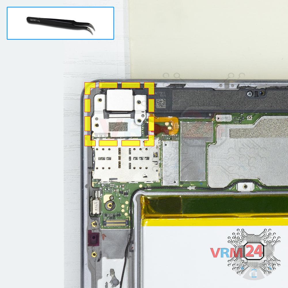
Remove the bracket
Remove the bracket of the main camera.
Step 18.
Remove the loudspeaker
Pry the connectors and remove the two buzzers (loudspeakers) assemblies.
Step 19.
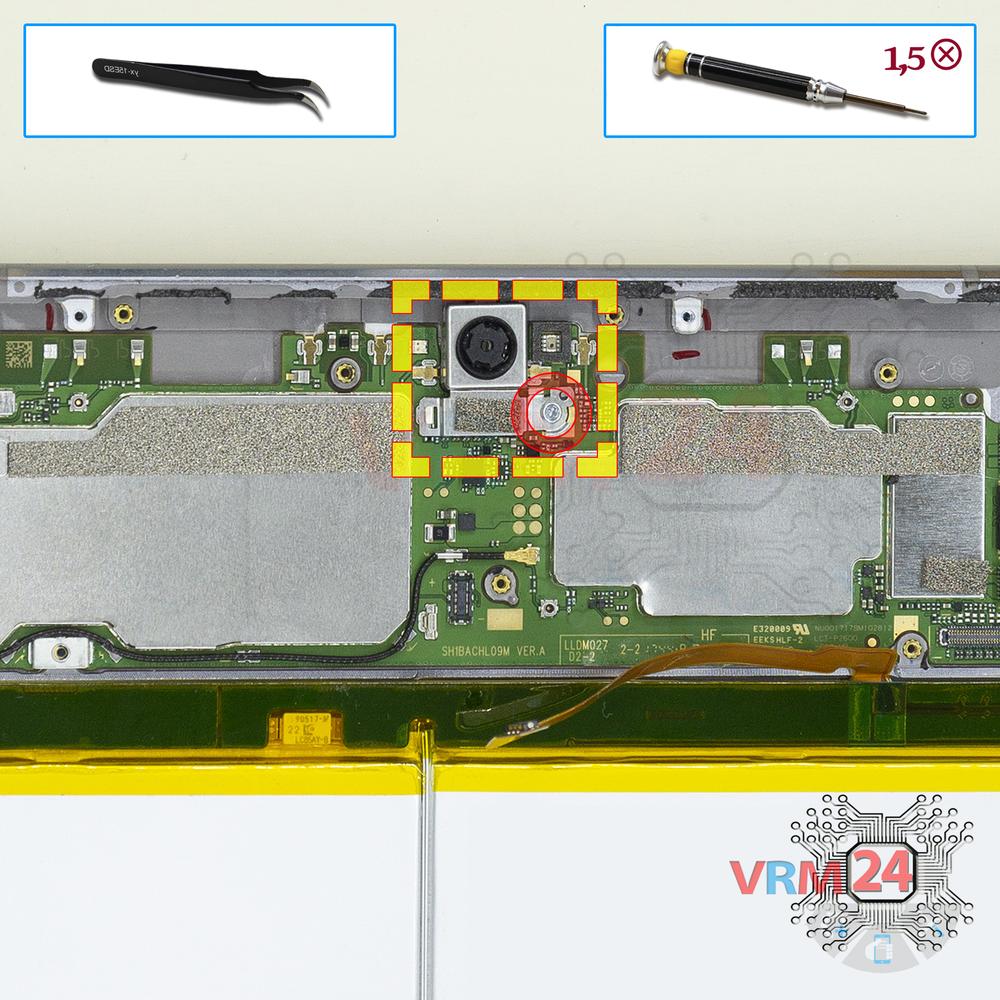
Unscrew one screw
Using a screwdriver (Phillips 1.5 mm PH000), unscrew 1 screw and remove the bracket holding the front (selfie) camera.
Step 20.
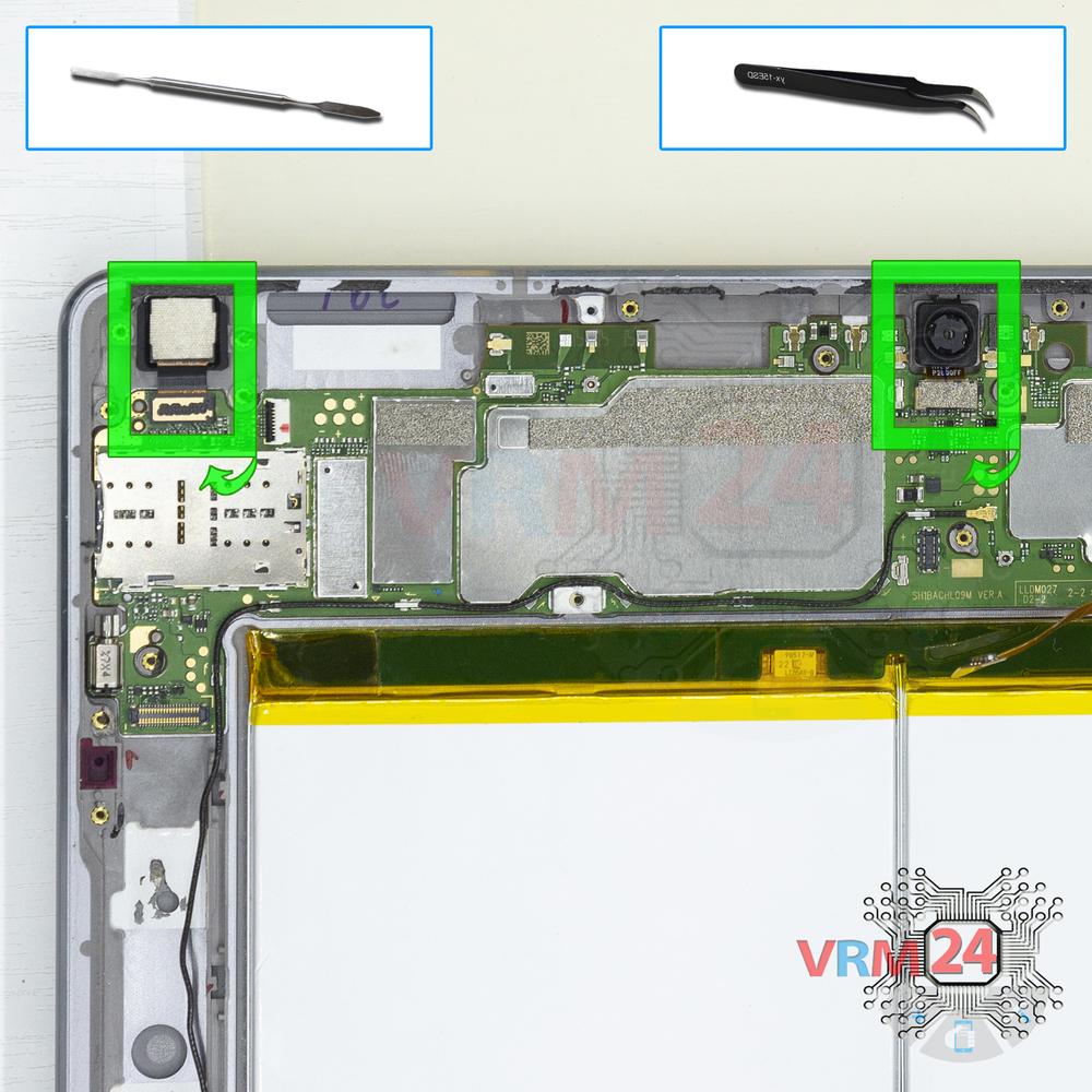
Remove the cameras
Disconnect connectors on PCB and remove the main and front (selfie) cameras.
Step 21.
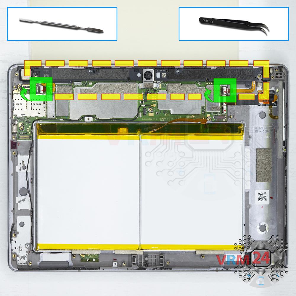
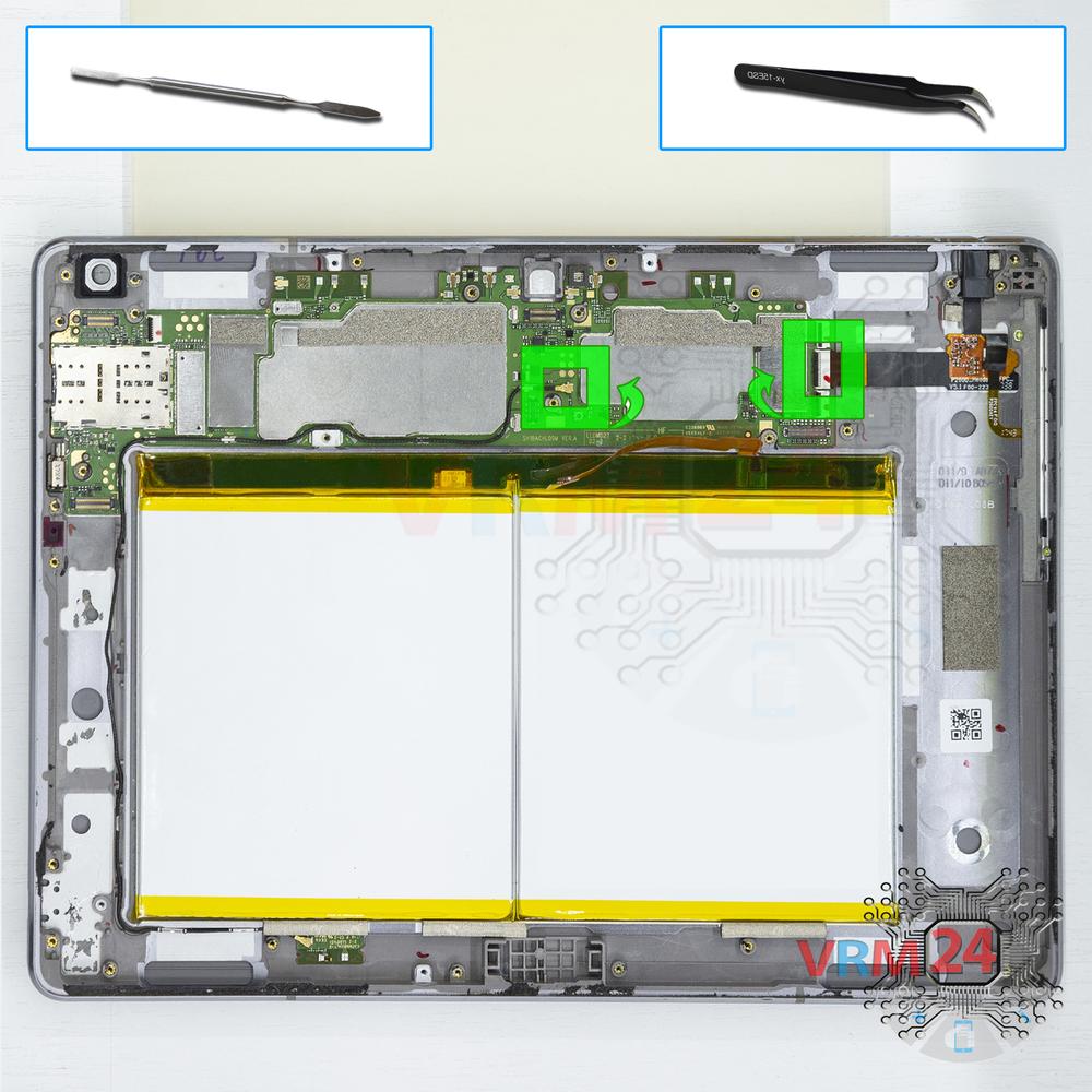
Disconnect the connectors
Disconnect connectors on the PCB.
Step 22.
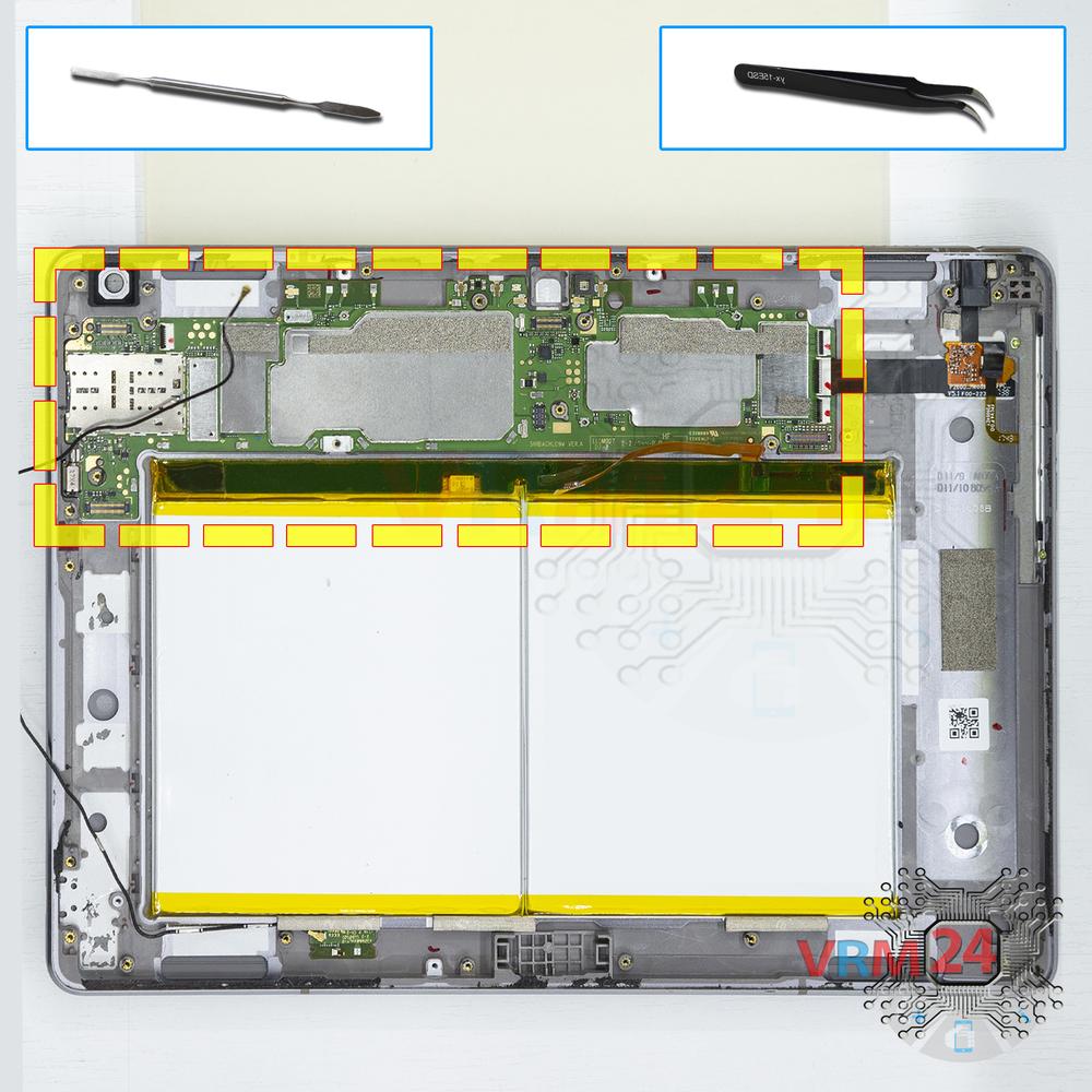
Remove the motherboard
Remove the PCB.
Step 23.
In the display frame remained
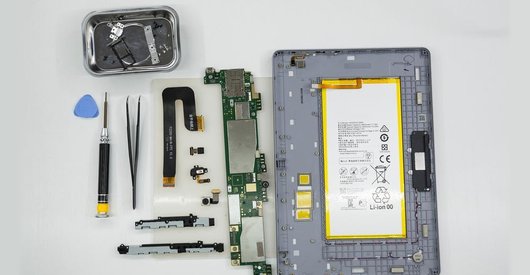
Parts are in the frame of the display module.

If you have a question, ask us, and we will try to answer in as much detail as possible. If this article was helpful for you, please rate it.

18510
Views
2
Likes
—
Share
19
Questions
Related Instructions
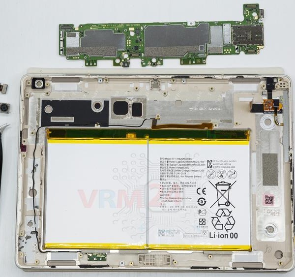
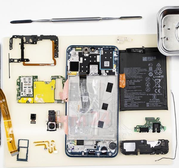
Related Reviews

Related Blog

Popular Questions
K
Huawei MediaPad M3 Lite 10''
Tnx dear Your video not go to west its to much useful 🥰
Khan Mobile7Huawei MediaPad M3 Lite 10''
Sir can i ask can i transfer the fingerprint sensor if i buy a lcd replacement that does not have a finger print sensor and why is my replacement scr…
landerjay
R
Huawei MediaPad M3 Lite 10''
T3 has the same battery like M3? Its the same dimension?
robson robsonovski17
A
Huawei P10 Lite
What fat did you use to soften the glue ? please
All mobile games15
D
Huawei Nova 2i
hi, what is the name of the song you used in the second half of video, i would really like to find it, thankyou. Also thankyou for the tutorial, even…
damien azzopardi3Top instructions
Check our
Top Huawei instructions most liked by readers
New instructions
Check our
New Huawei brand instructions on vrm24.com