
⚠️️ Before disassembling, do not forget to turn your phone off.
Teardown difficulty:
Moderate
Moderate
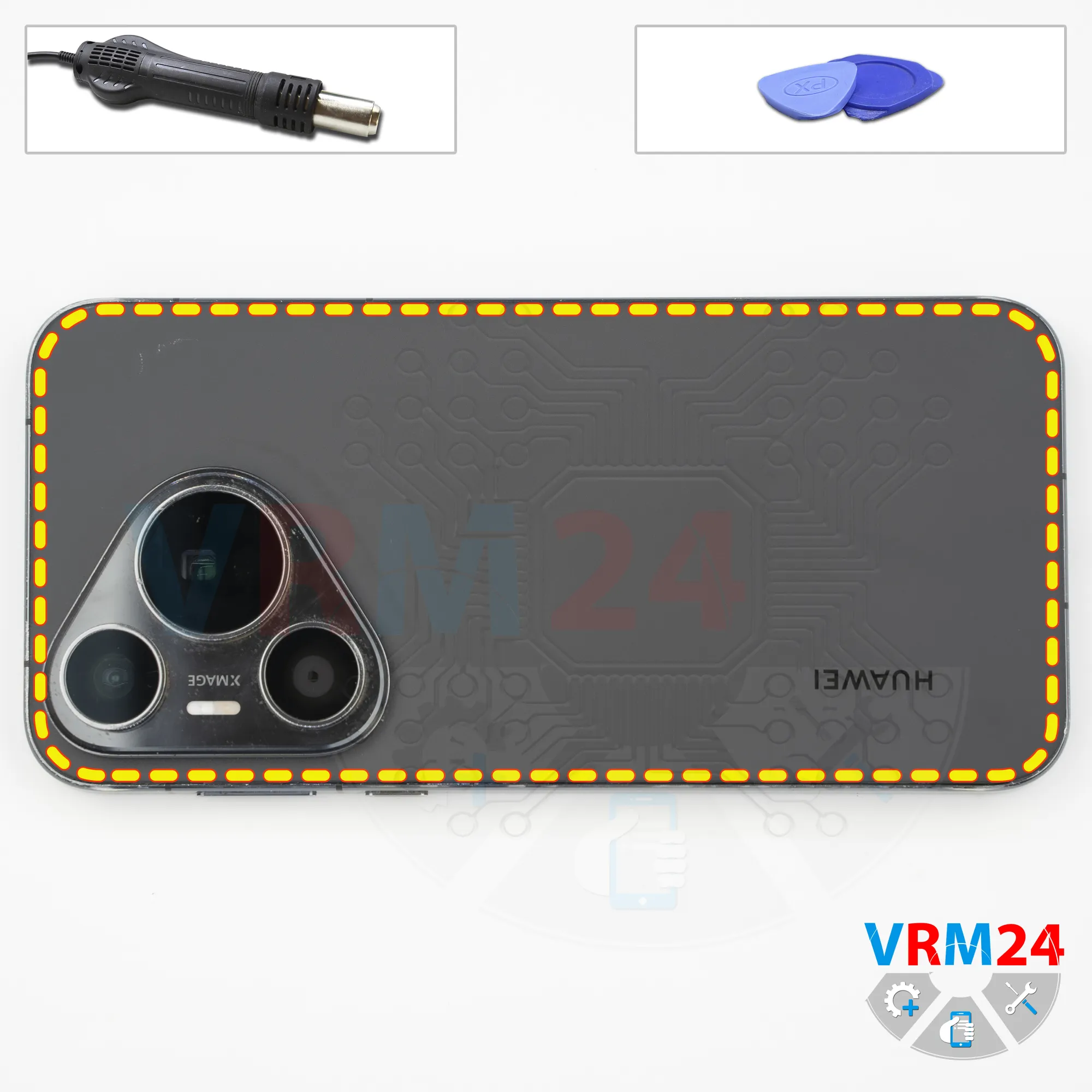
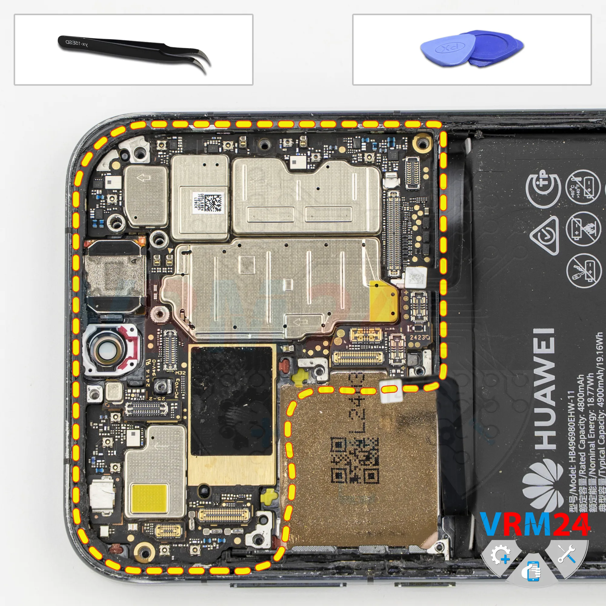
Recommended tools


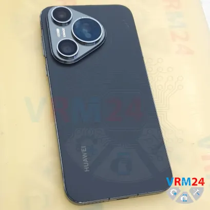
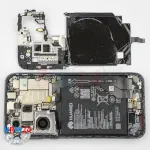
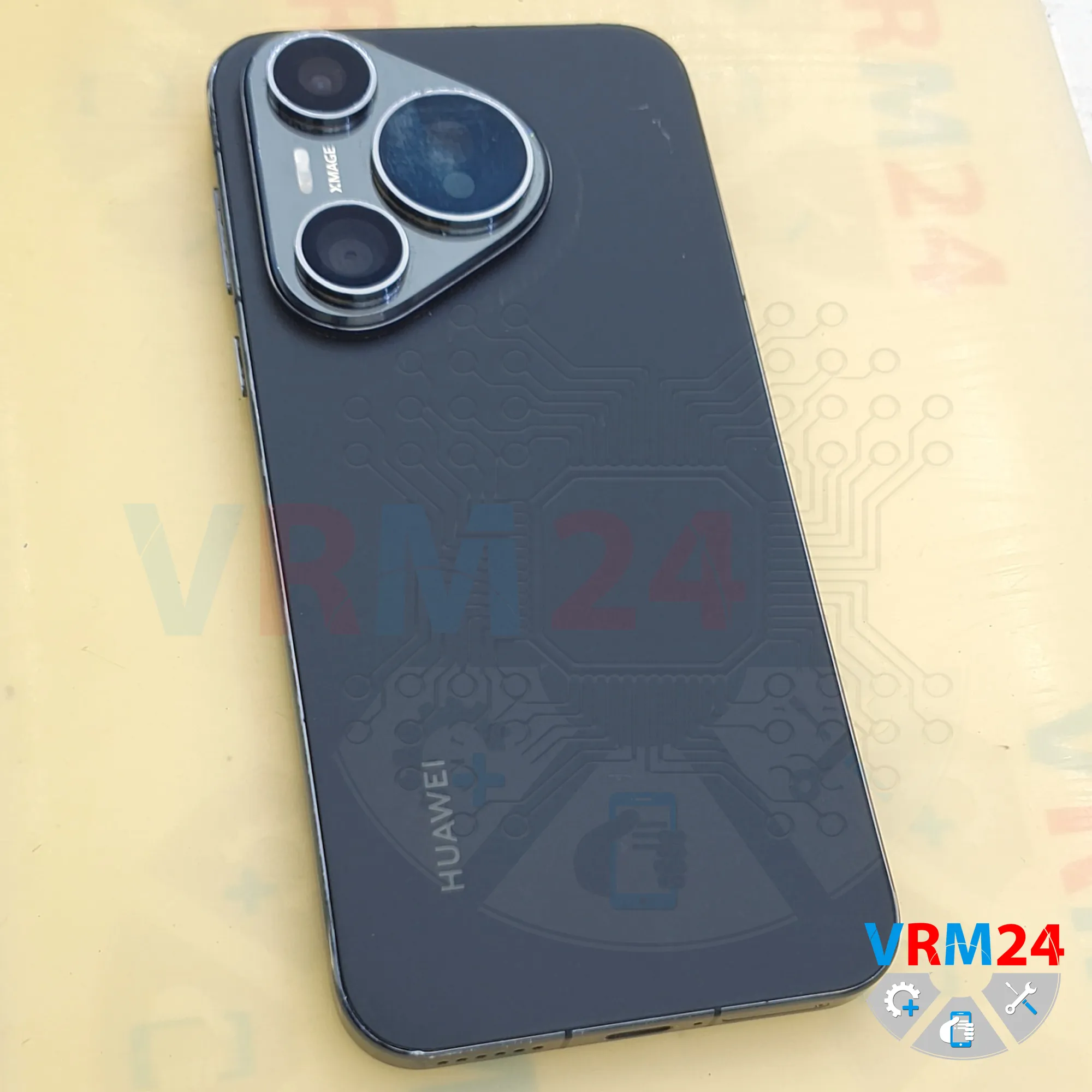
Disassembly/Repair of the mobile device Huawei Pura 70 (Huawei Pura 70 ADY-LX9) with each step description and the required set of tools.


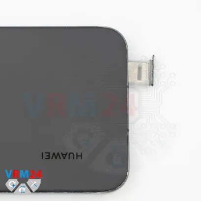
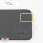
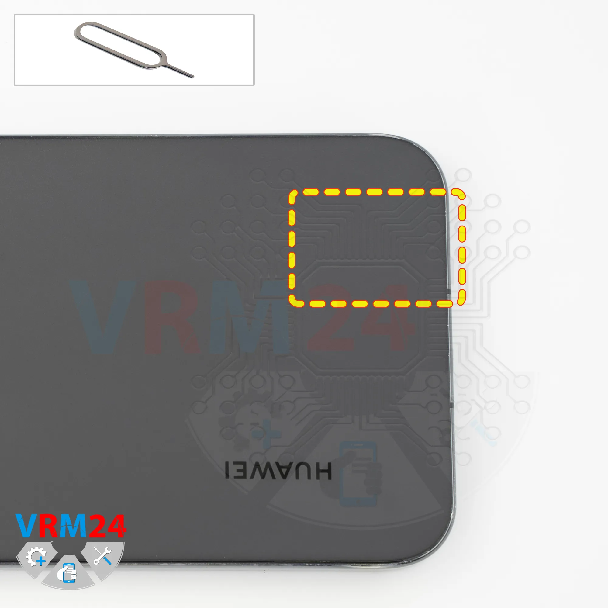
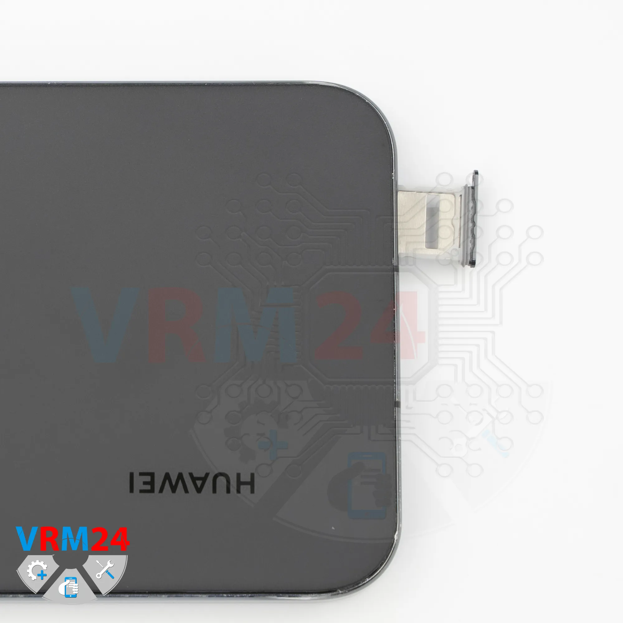
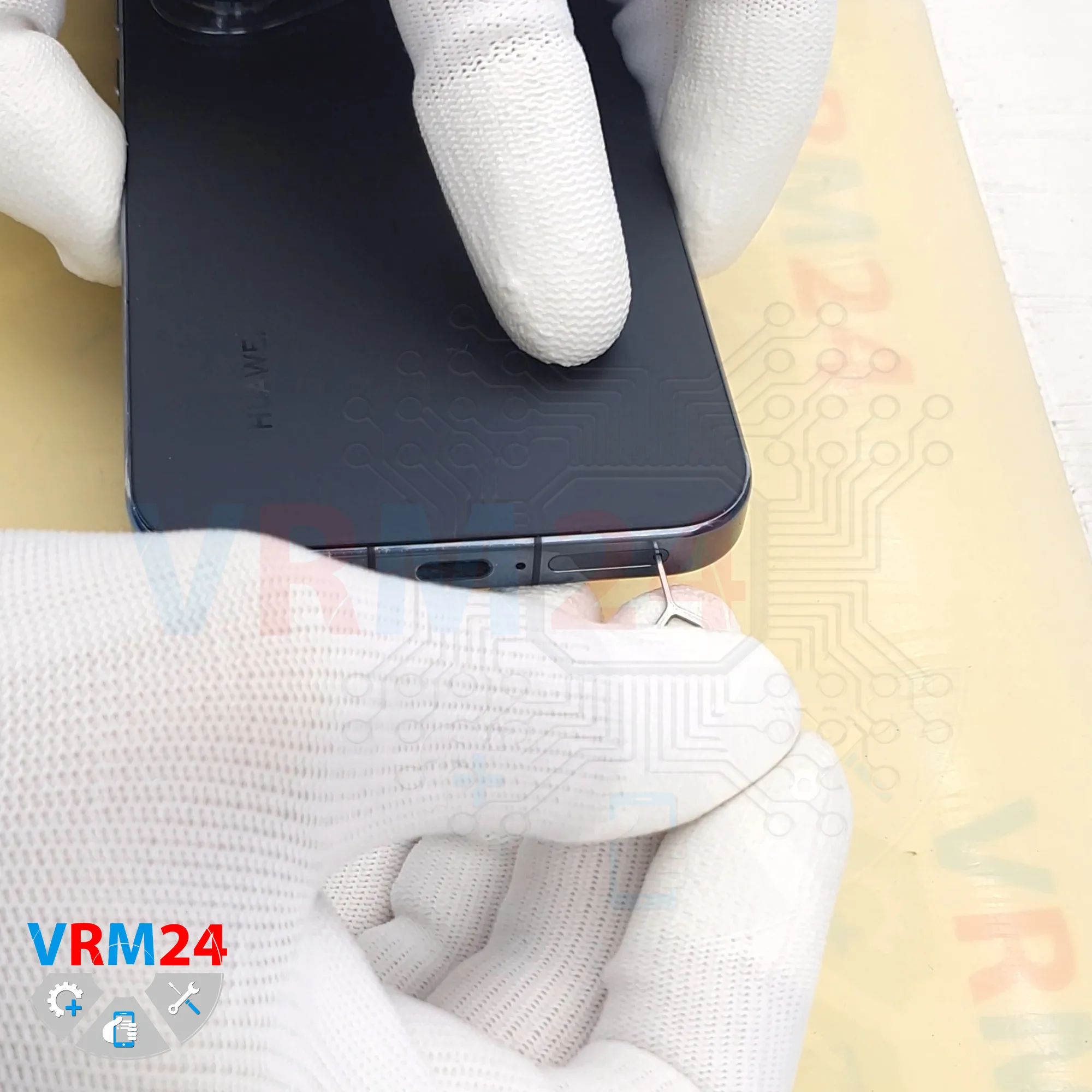
Step 2. Remove the tray
First, we need to remove the SIM card tray.
To do this, we use a SIM eject tool, insert it into the hole, push the tray out, and set it aside.
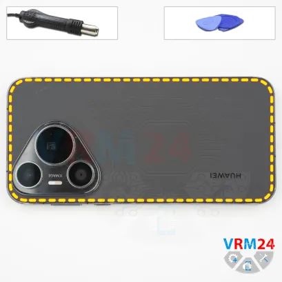


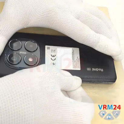


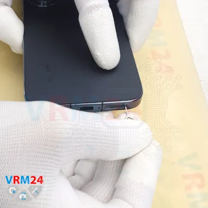
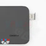
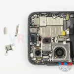
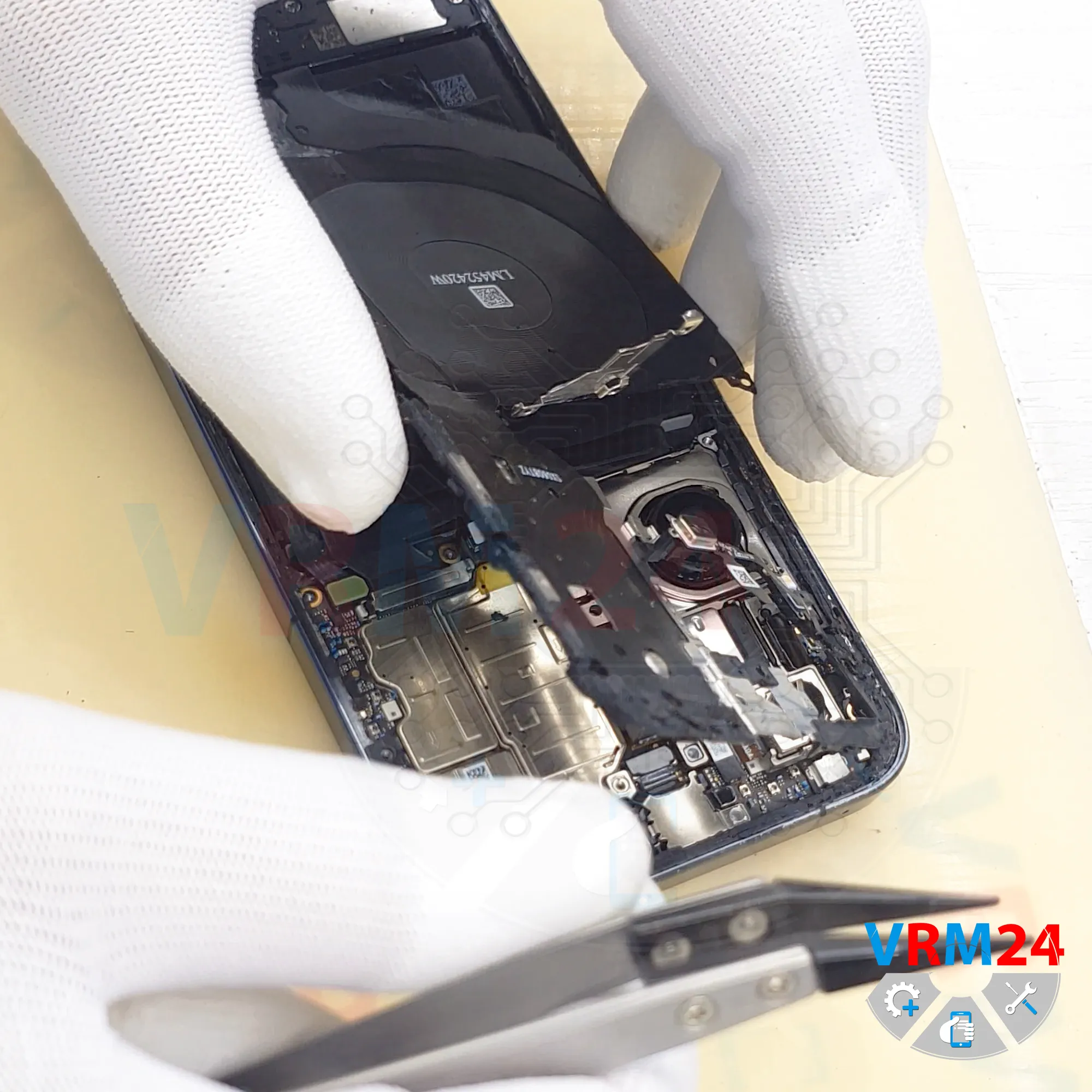
Step 3. Open the back cover
After that, we need to heat the surface of the back cover to approximately 70°C or 160°F. We’re using a heating mat for this, but you can also use a heat gun or a hair dryer.
After about 10 minutes, we can move on to separating or removing the back cover.
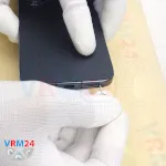
For this, we use a thin but fairly durable plastic film. We insert it into the gap between the back cover and the midframe, then carefully slide it along the edge, cutting through the adhesive layer.
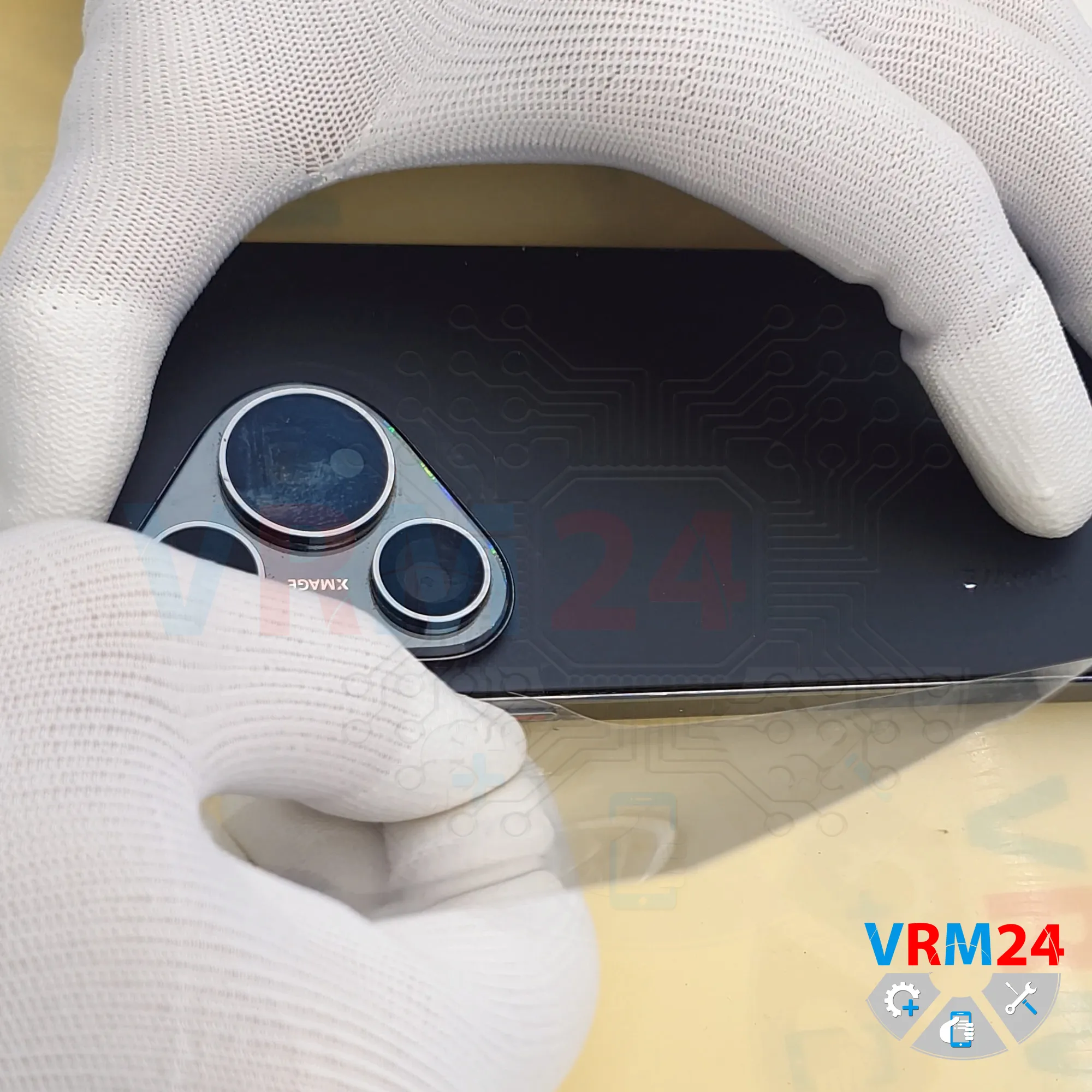
As always, you need to be careful around the camera area to avoid accidentally touching or damaging the lenses.
And of course, you shouldn’t push the film in too deeply, since we don’t know what components are located underneath the back cover.
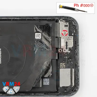
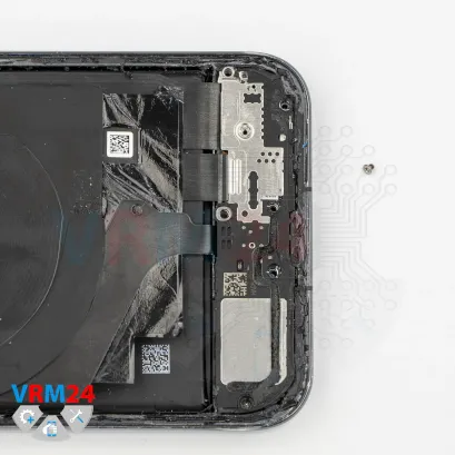
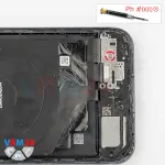
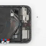
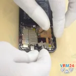
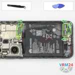
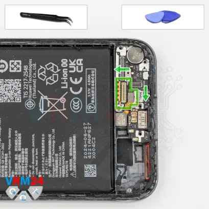
Step 4. Unscrew the screws
In this section we can unscrew three screws that hold the bracket that covers the battery connectors.

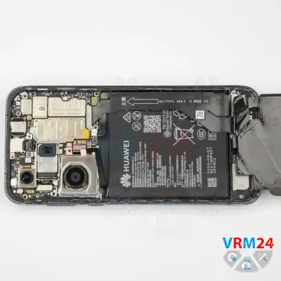
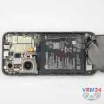
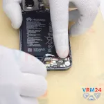
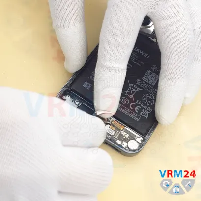
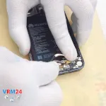
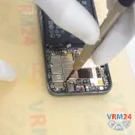
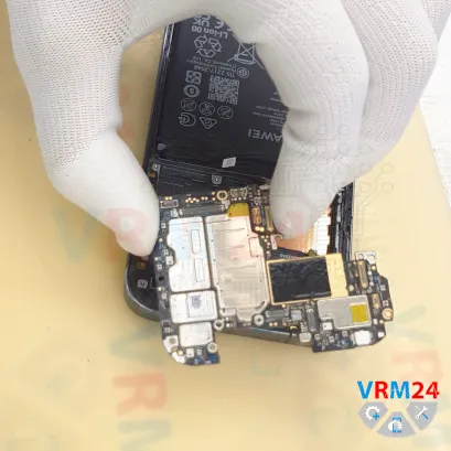
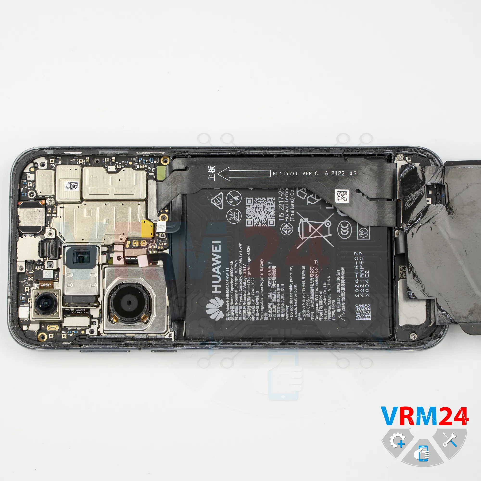
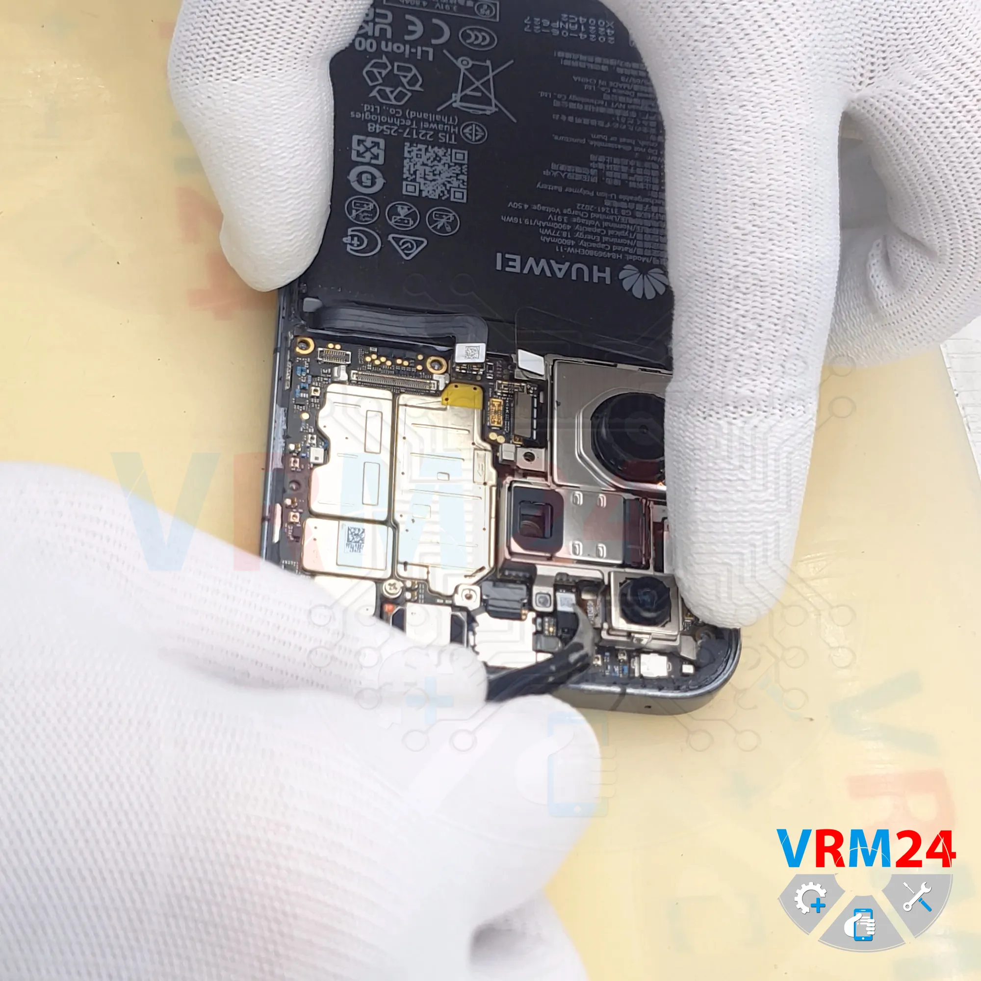
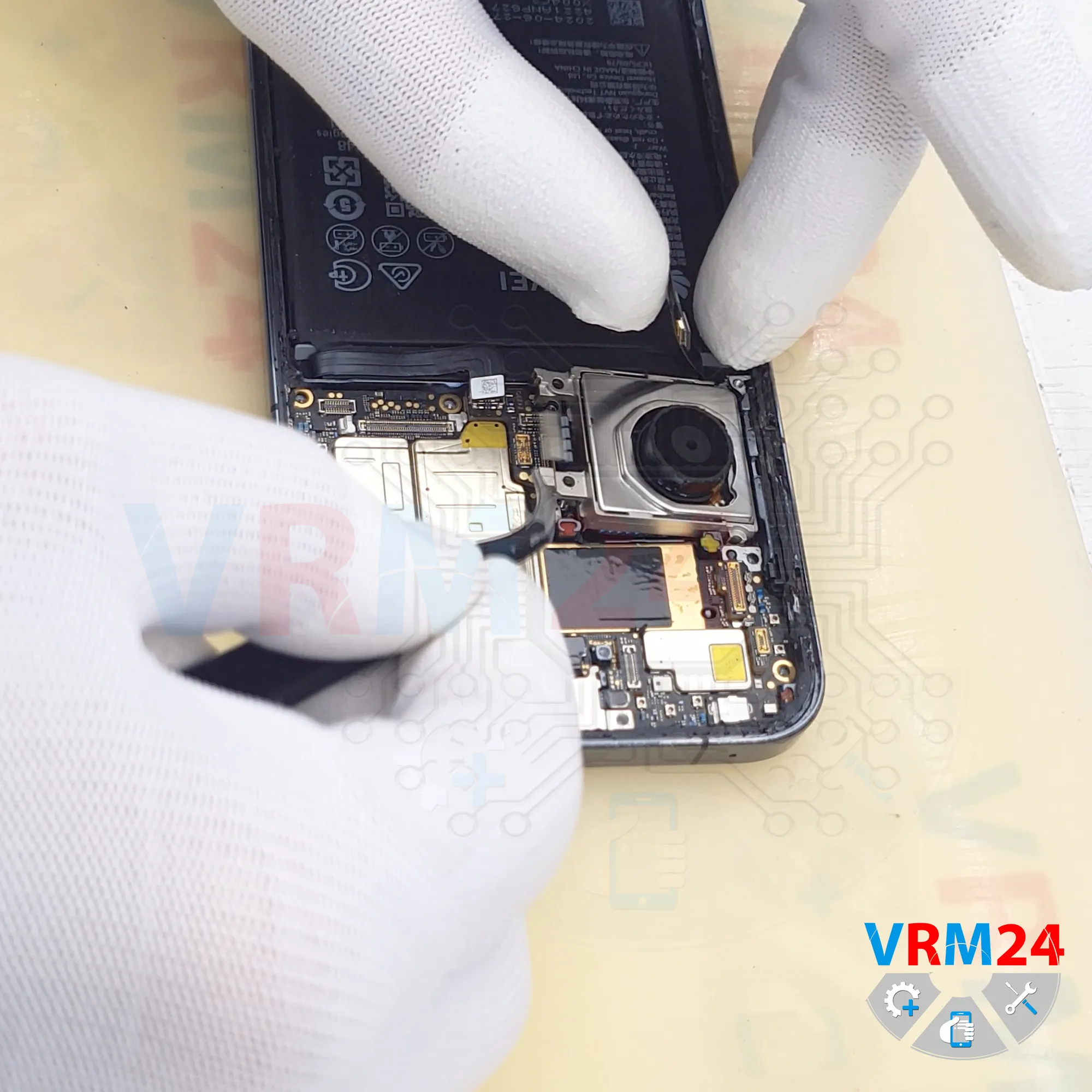
Step 5. Disconnect the battery connector
We lift the bracket and disconnect the two battery connectors.
ℹ️️ The Huawei Pura 70 ADY-LX9 uses a HB496980EHW-11 rechargeable battery with a capacity of 4900 mAh.
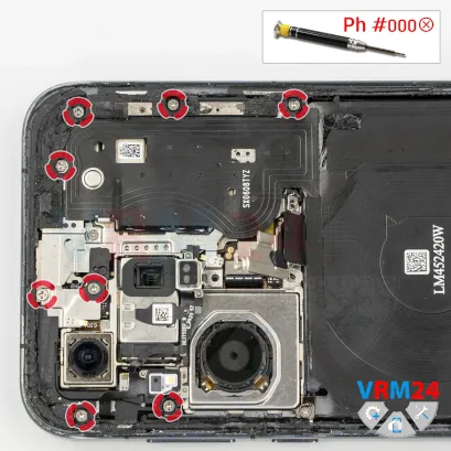


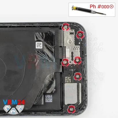
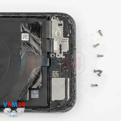
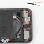
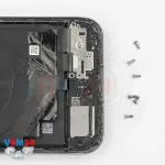
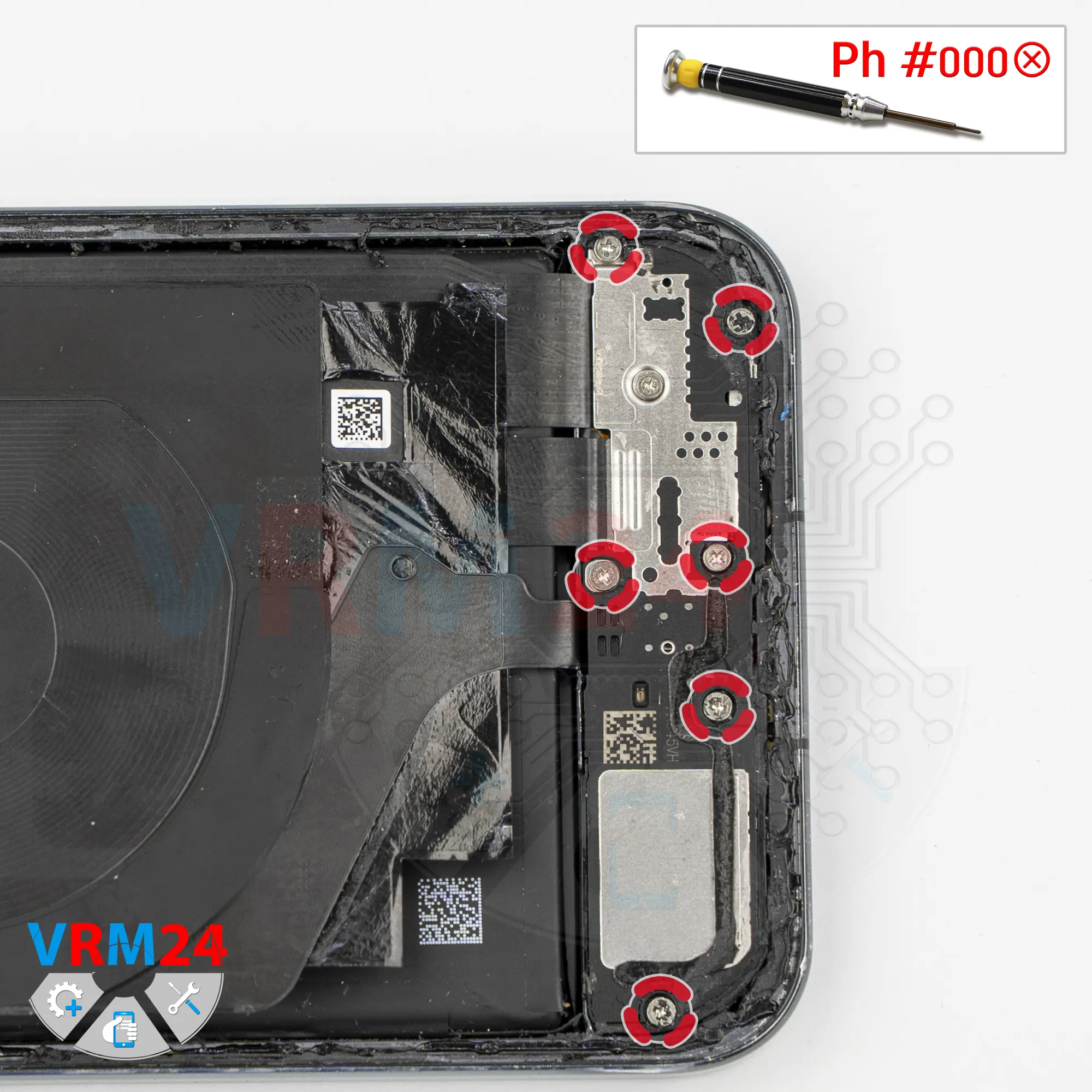
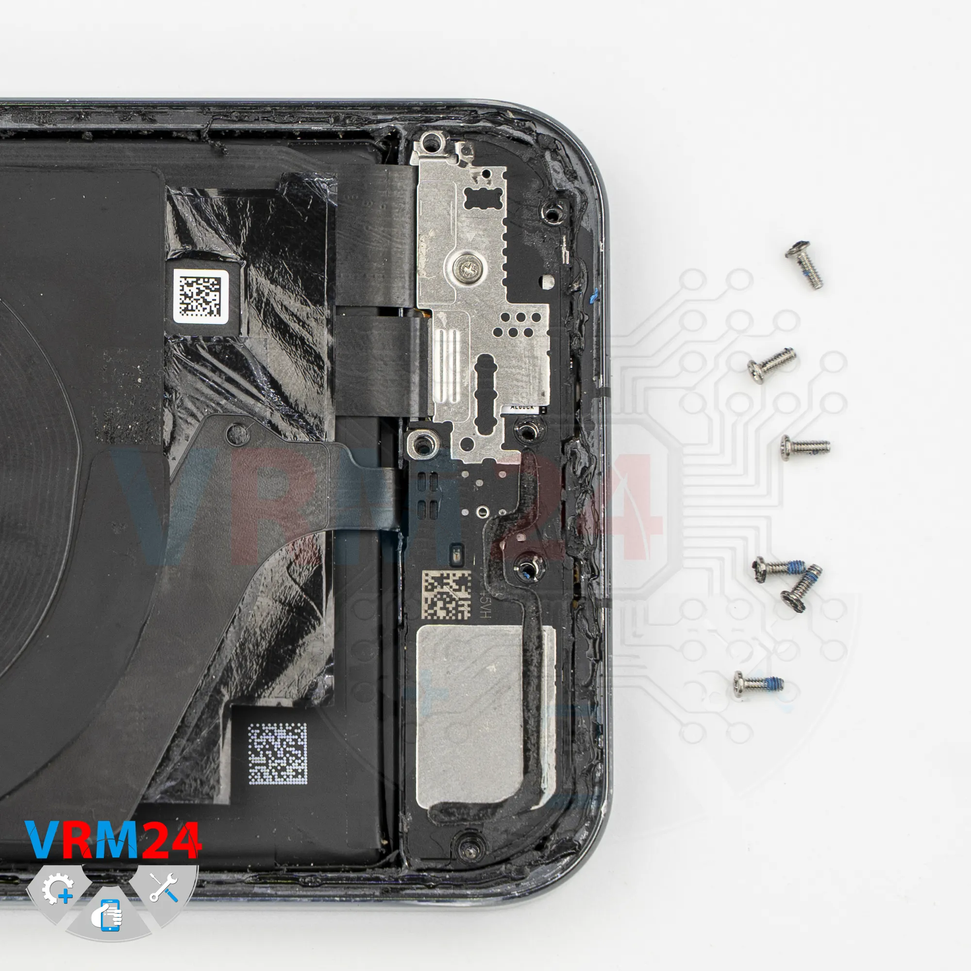
Step 6. Unscrew the screws
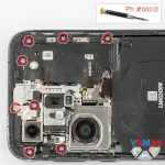
After that, we move on to removing the large screws from the upper section.
For this, we use a 1.5 mm Phillips screwdriver or a Phillips #000 screwdriver.
It’s best to arrange the screws in a specific order on a dedicated surface, since the screws vary in size and are installed in different locations.


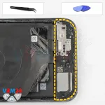
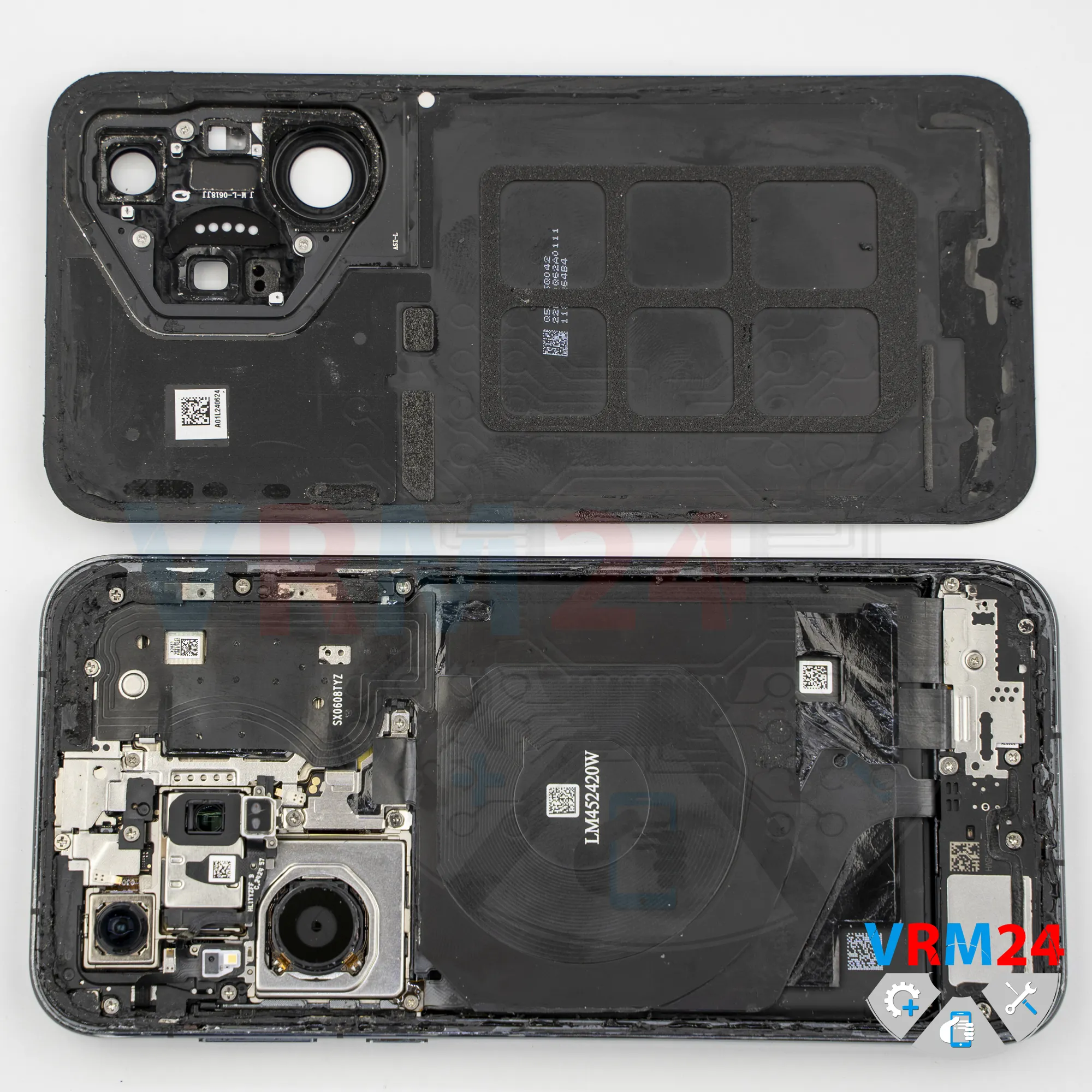
Step 8. Open the cover
After that, we’ll need to detach the upper cover assembly.
And we check where the flex cable runs. There’s probably a connector on the opposite side.
So, we carefully lift from the edge, gently raise the cover, and try to disconnect it.
And indeed, there is a connector on the opposite side, and the flex cable runs exactly to that location.
We need to carefully disconnect the connector to avoid damaging it or the flex cable, which most likely goes to the flash module.


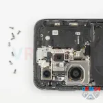
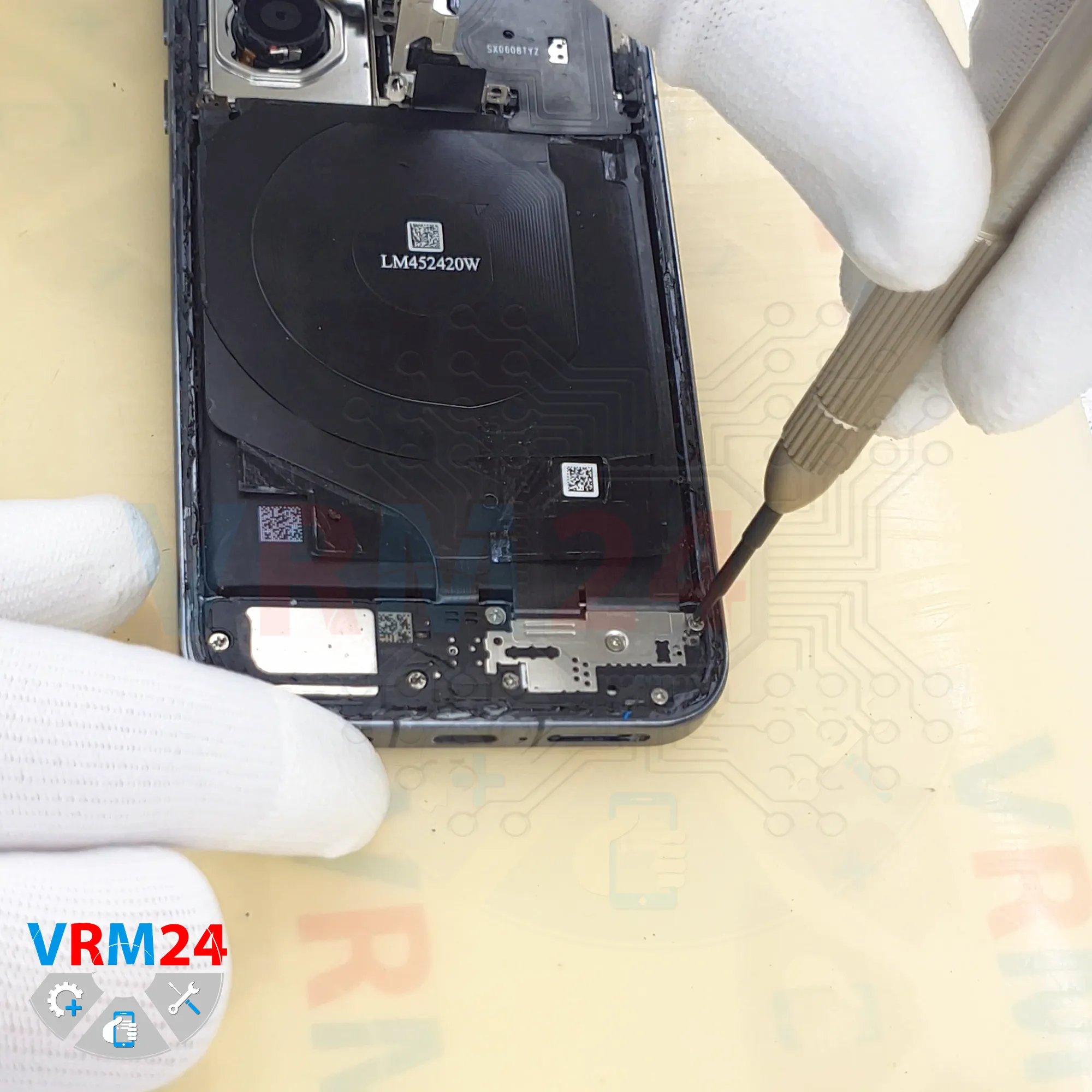
Step 9. Unscrew the screws
In the lower section, we also unscrew the large screws using the same Phillips #000 screwdriver.

Step 10. Unscrew one screw
We unscrew the one screw that is also different in size.
So the screws should likewise be arranged in order on a dedicated surface, photographed, or marked to avoid mixing them up during reassembly.


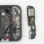
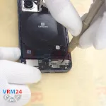
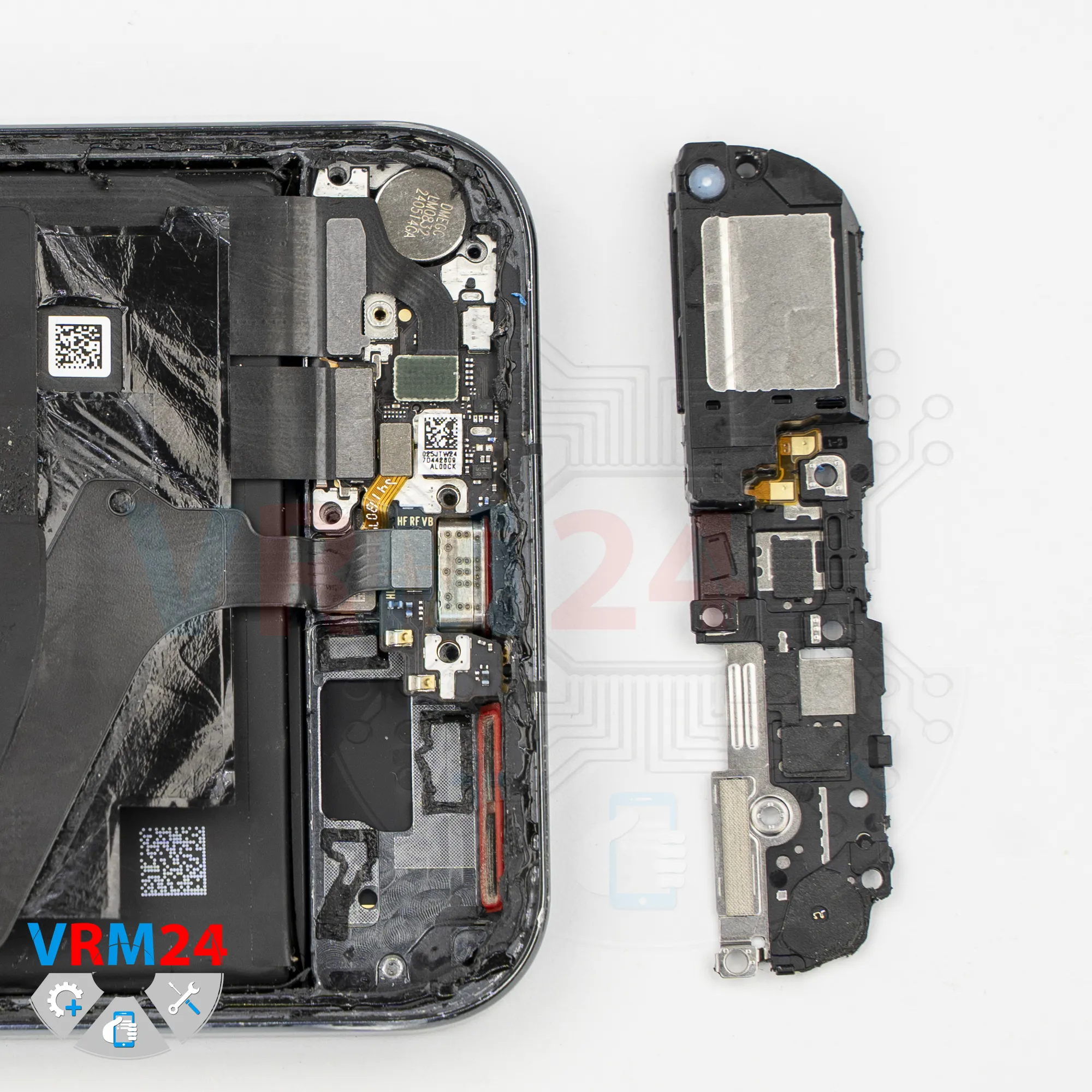
Step 11. Remove the loudspeaker
After that, we can disconnect the cover.
Carefully lift from the edge in the correct location and try to raise it.
We should not lift the cover in areas where connectors and flex cables are located, in order to avoid damaging the flex cables or the traces on them.
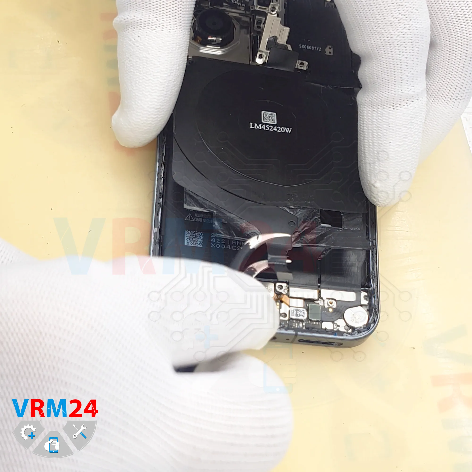
Carefully lift and disconnect it. As we can see, the loudspeaker is mounted on the cover.

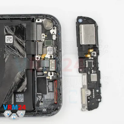
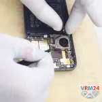
Step 12. Remove the wireless charging
Then disconnect the wireless charging connector and remove the cover assembly, which most likely includes the NFC module.
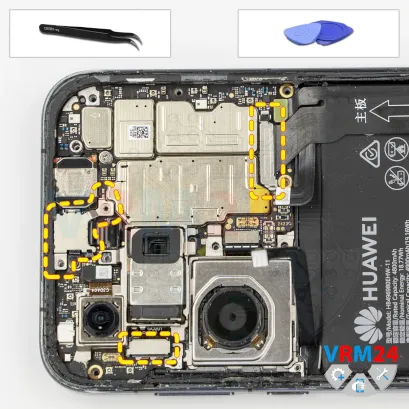


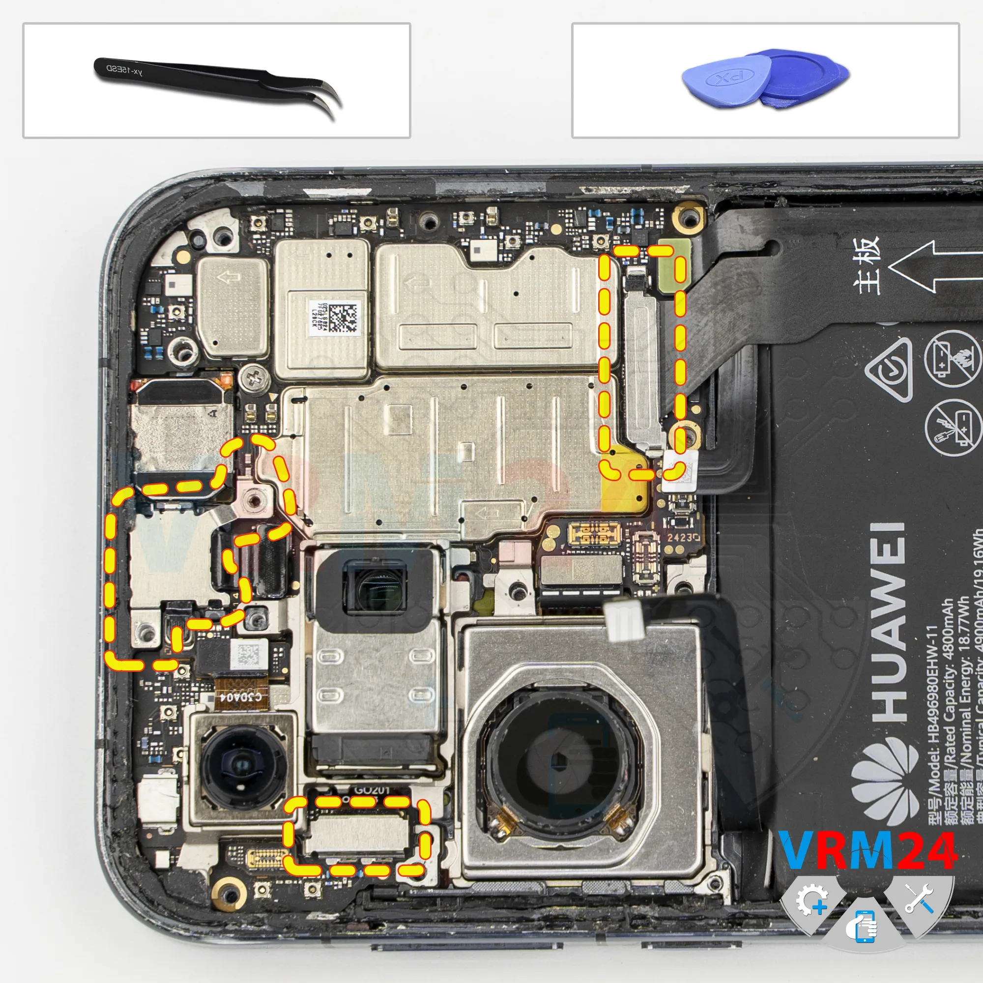
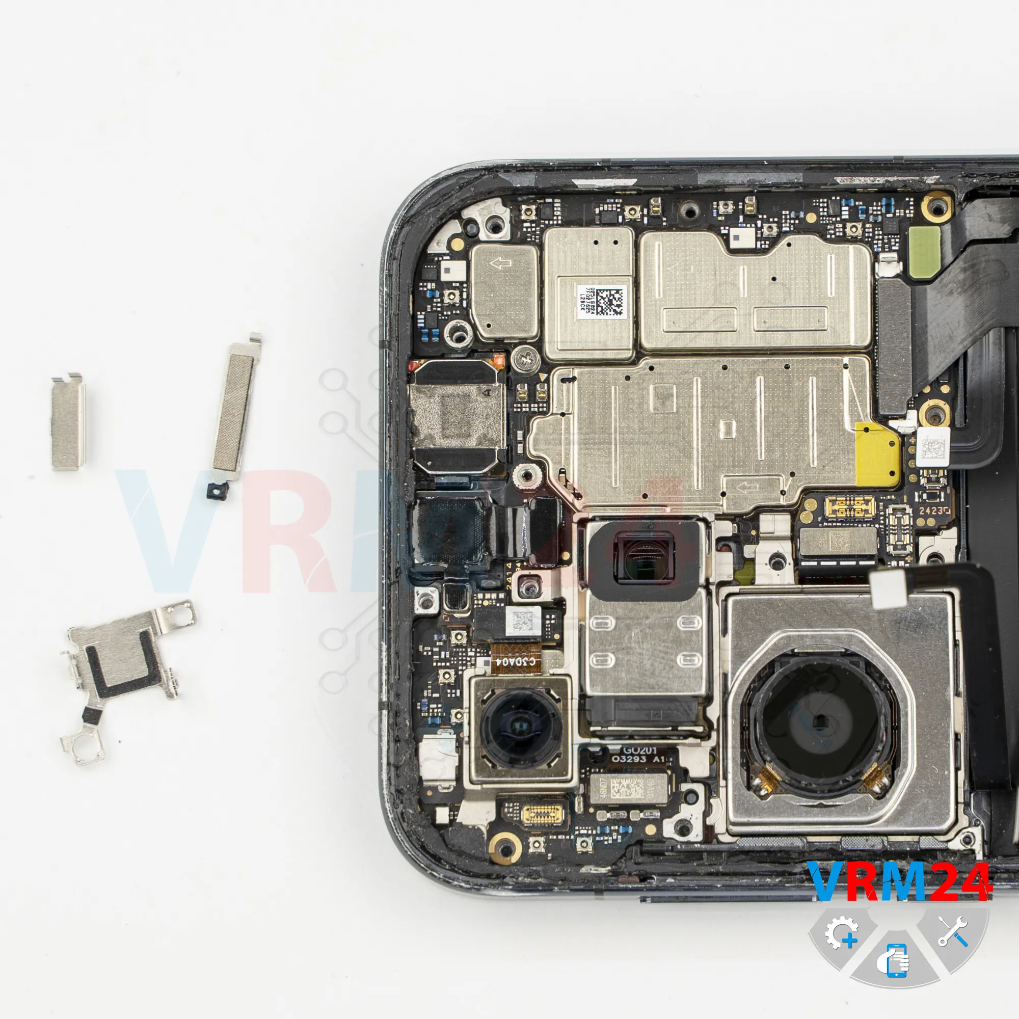
Step 13. Remove the bracket
Now we can remove the brackets that hold the front camera, rear camera, interconnect cable.


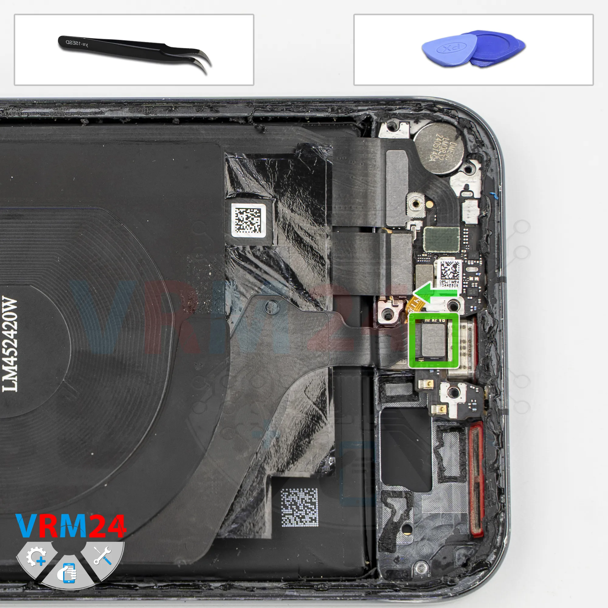
Step 14. Remove the interconnect cable
After that, we need to disconnect the interconnect flex cable connectors.
We disconnect them on the sub-board side. As we can see, there are three connectors.
Then we disconnect them on the motherboard side. And we set the cable aside.
And as we can see, the cable has an arrow indicating the direction toward the motherboard.

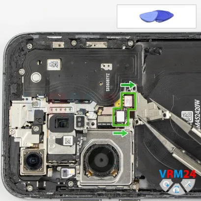
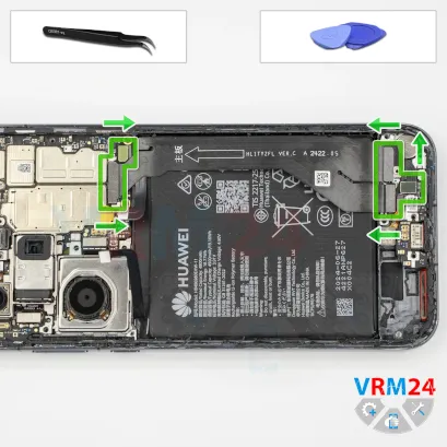
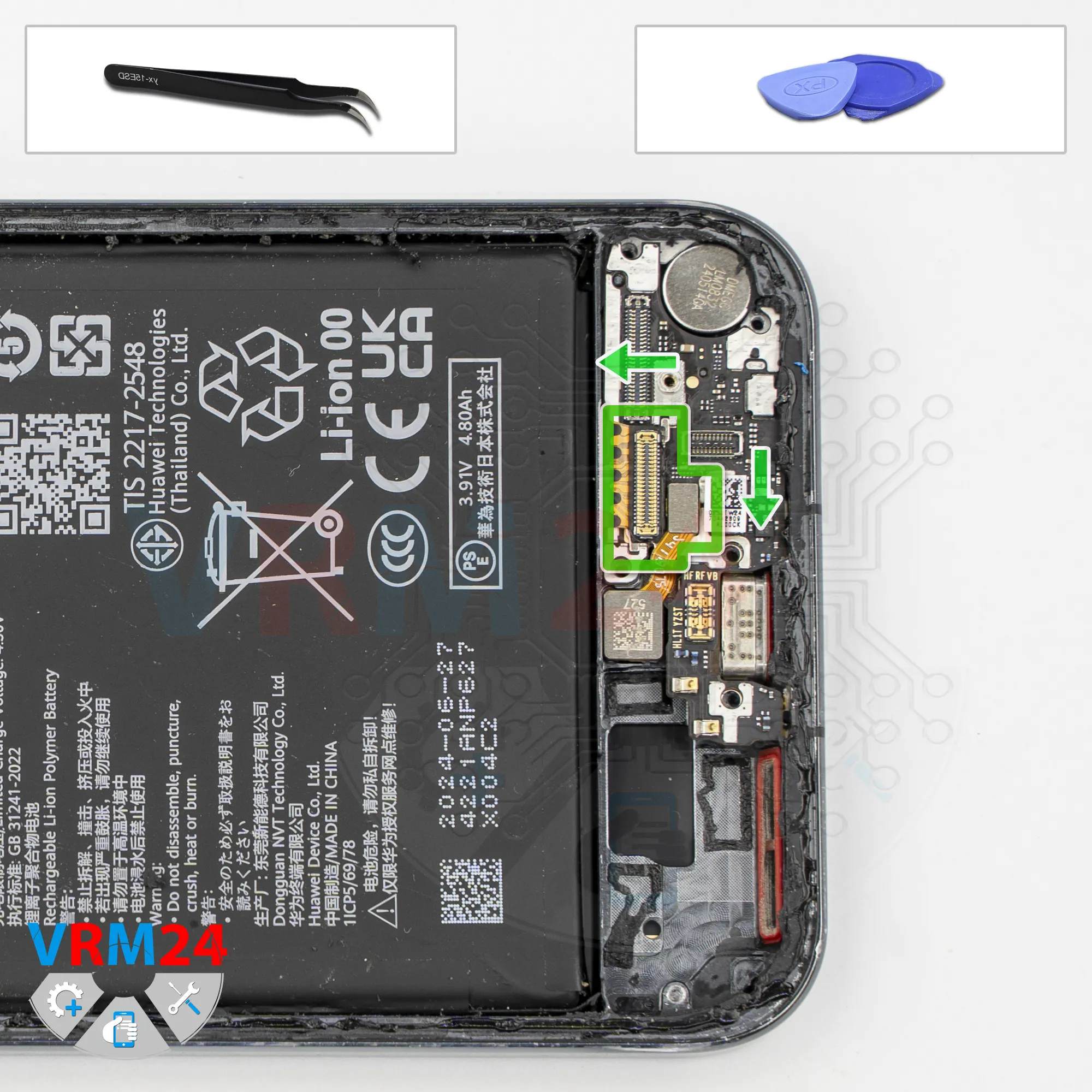
Step 15. Disconnect the connectors
Now we disconnect the remaining connectors. We disconnect the fingerprint sensor connector.
We also need to disconnect the display flex cable connector. We need to lift it carefully by the thin metal tab on the edge.
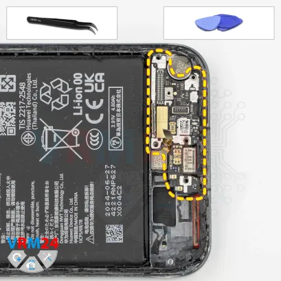
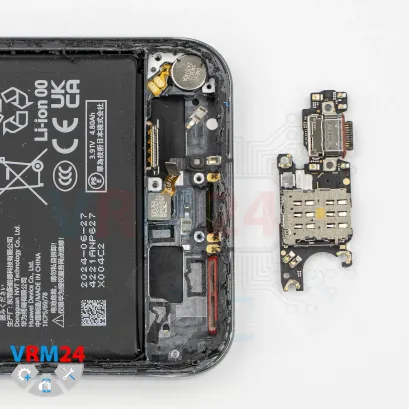


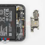
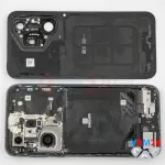
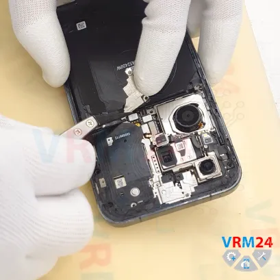
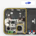
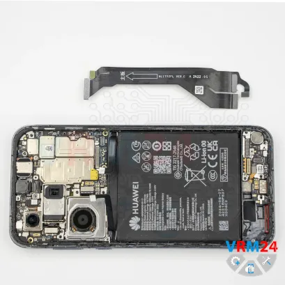
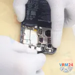
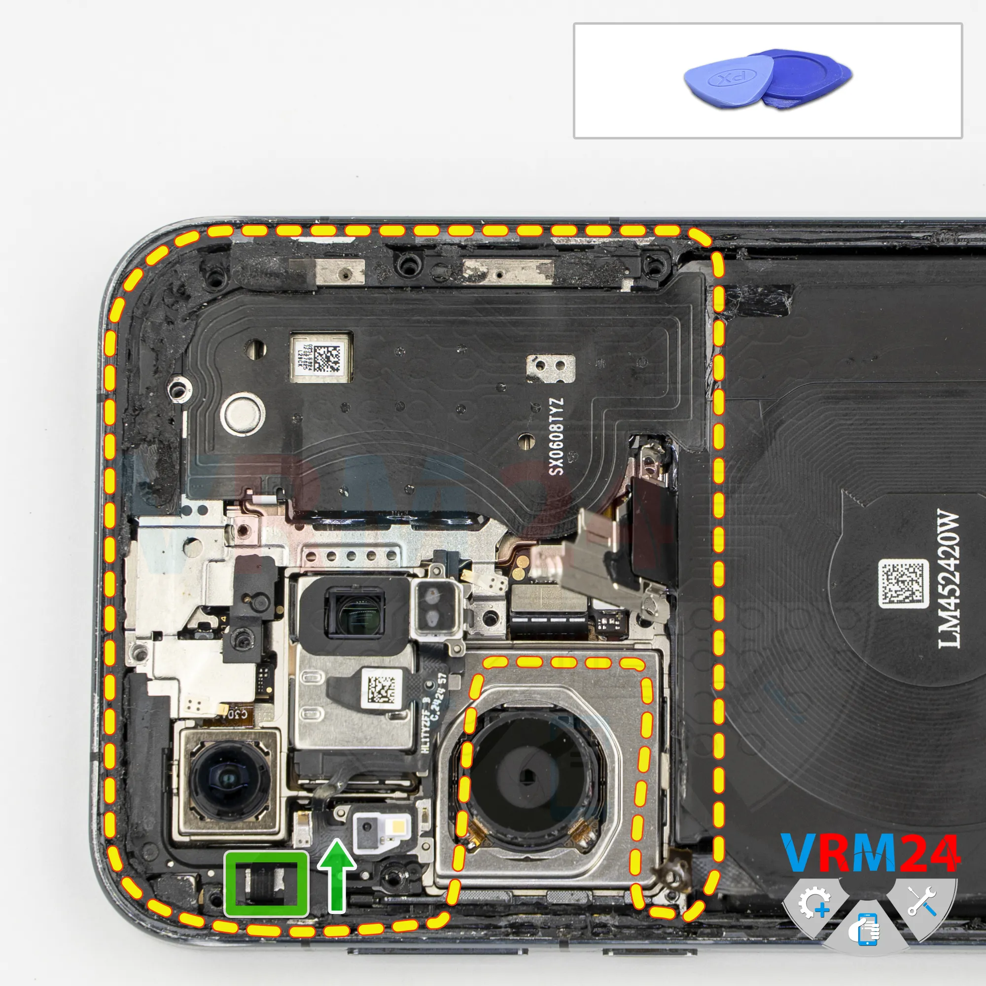
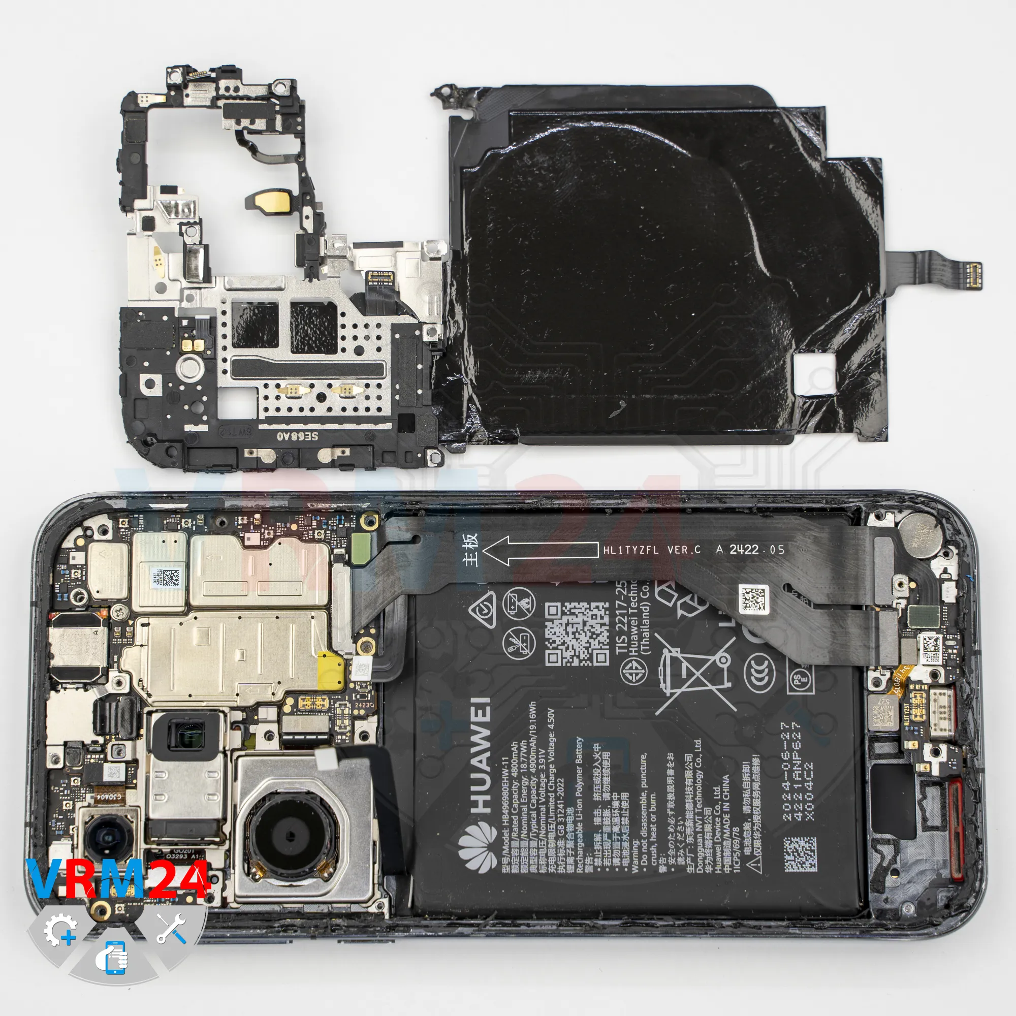
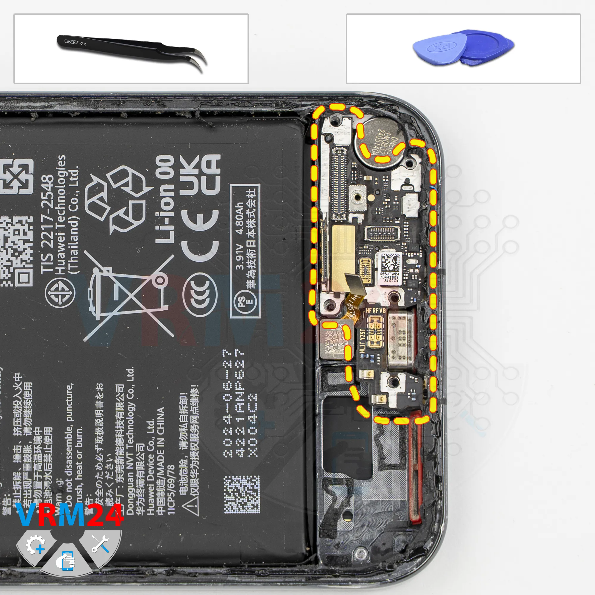
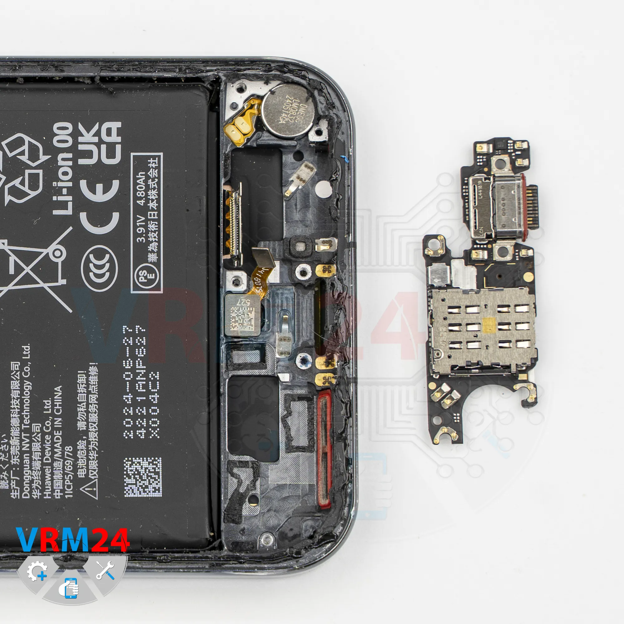
Step 16. Remove the sub-board
And now we can remove the sub-board, which is recessed into the frame.
Carefully lift it, gently rock it side to side, remove it, and bend the flex cables out of the way so they don’t interfere.
So, the sub-board contains the charging port, the microphone under the shield, and on the opposite side, the SIM card connector.
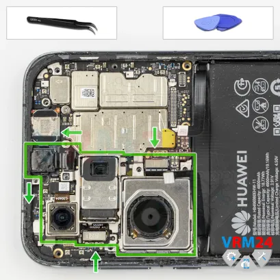

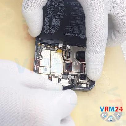

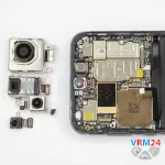
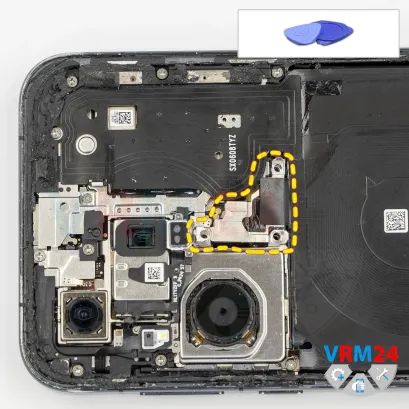
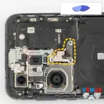
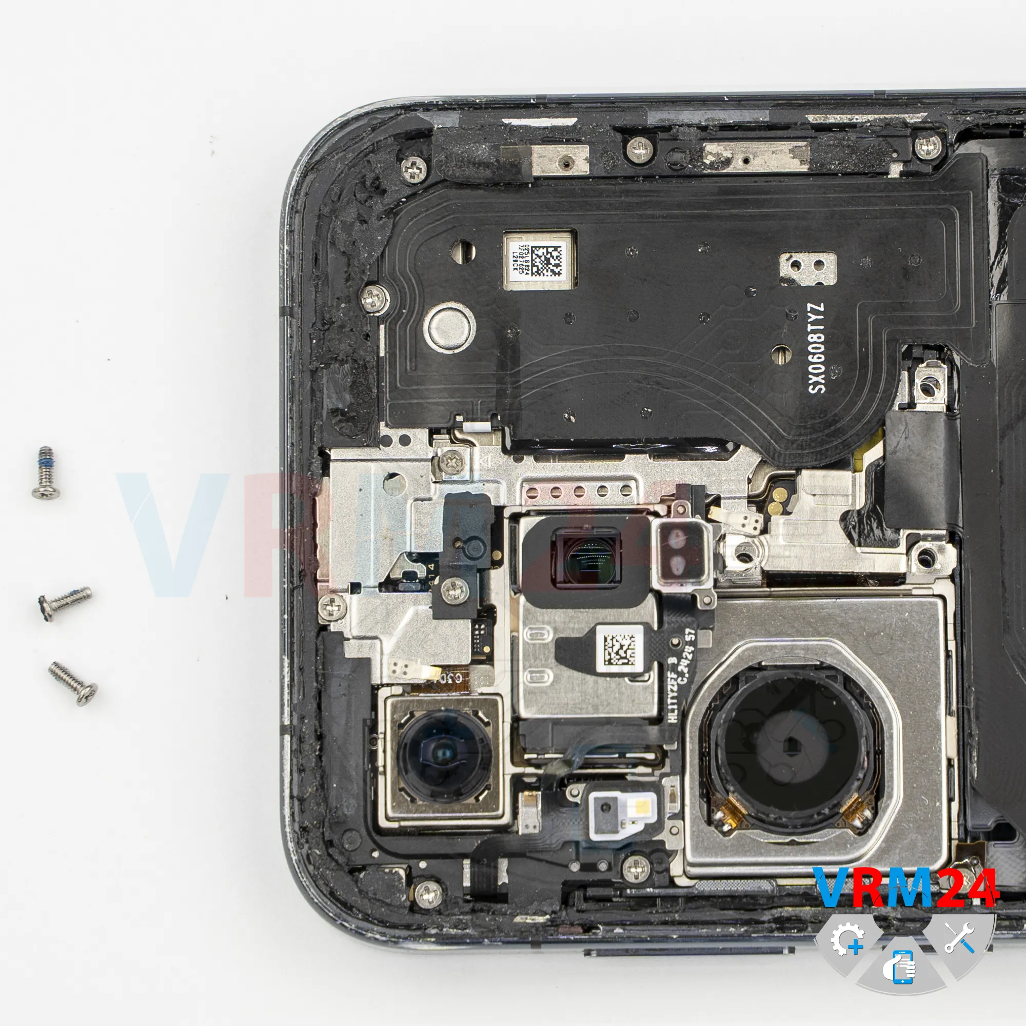
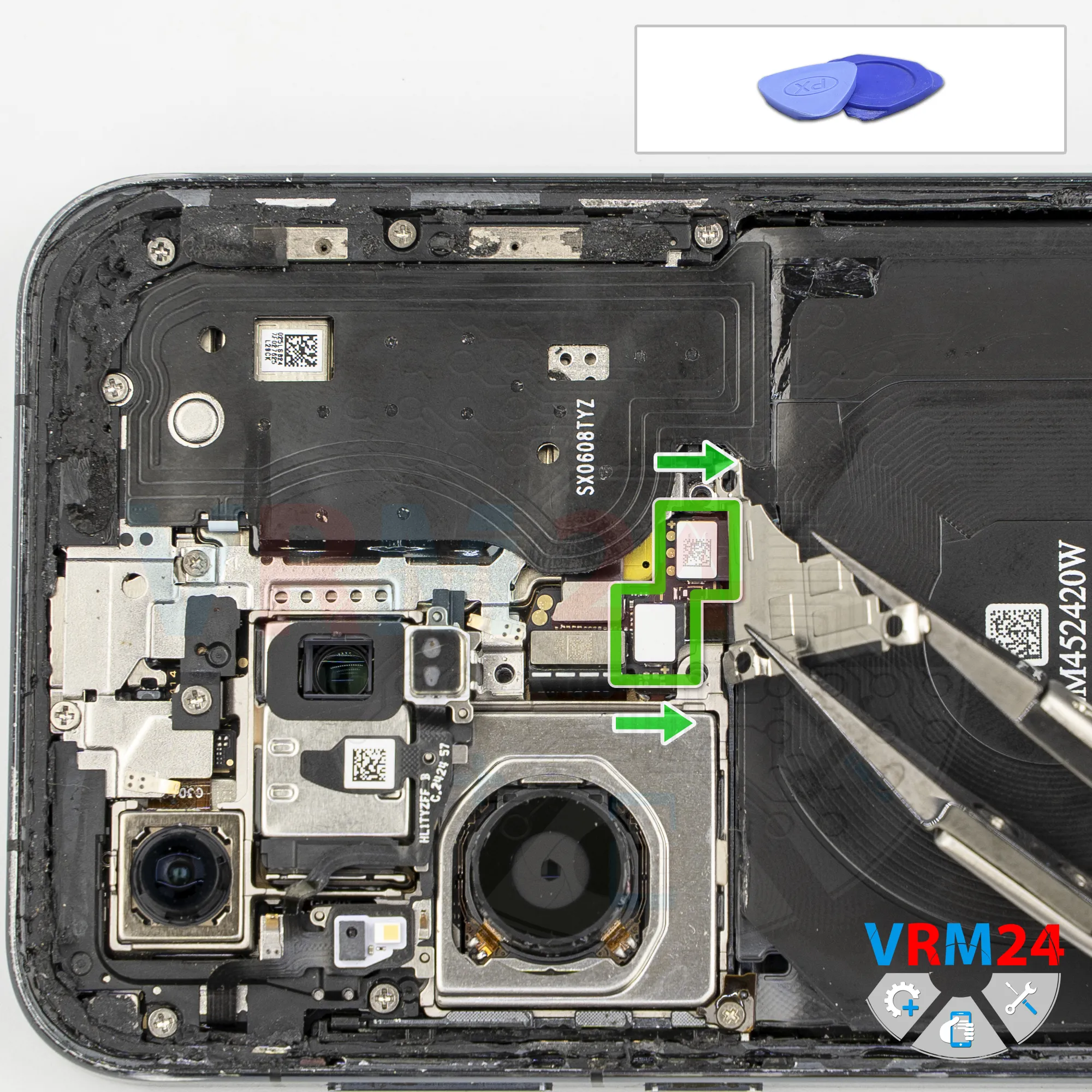
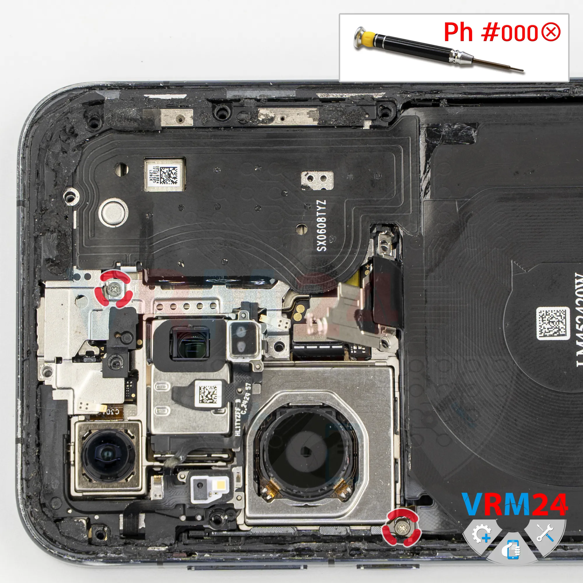
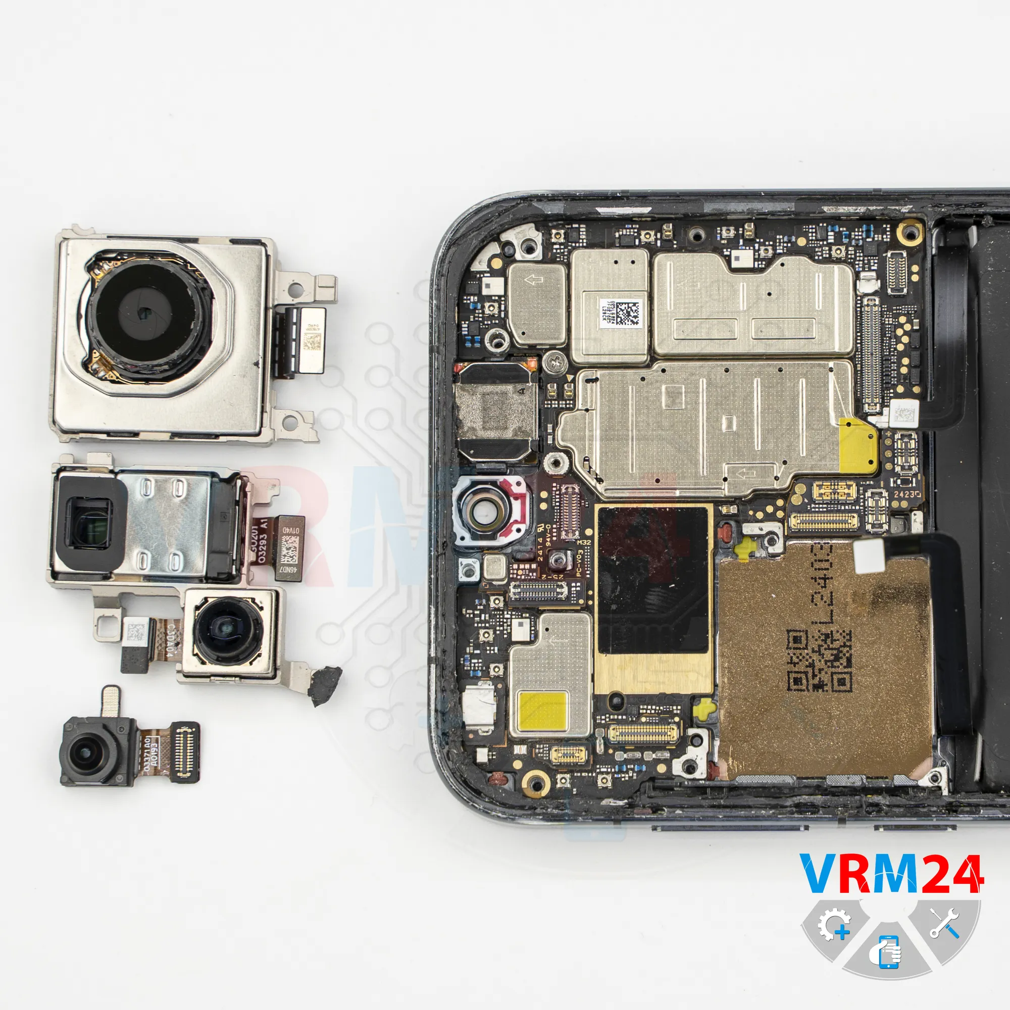
Step 17. Remove the cameras
And at some point, we can try removing the camera assembly.
Carefully. We check the order and determine what needs to be disconnected first. There’s no need to use force - simply lift carefully and remove the cameras.
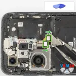
So, first we disconnect the dual rear camera assembly...
And after that, we can disconnect the large rear camera, also known as the main camera. We set the camera aside.
We also need to disconnect the front-facing camera. Disconnect the connector and carefully remove the front camera. Then set it aside.
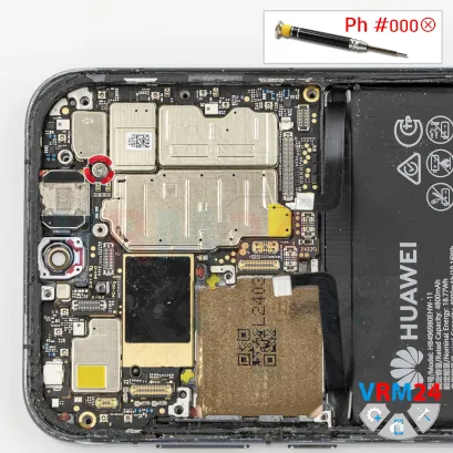
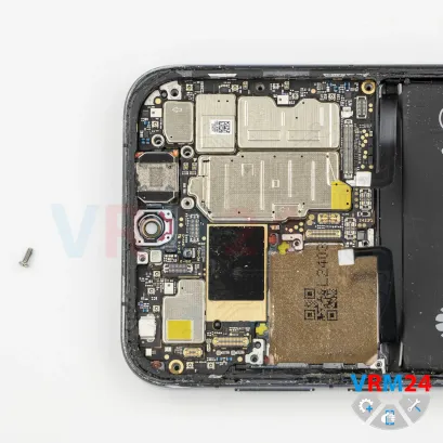
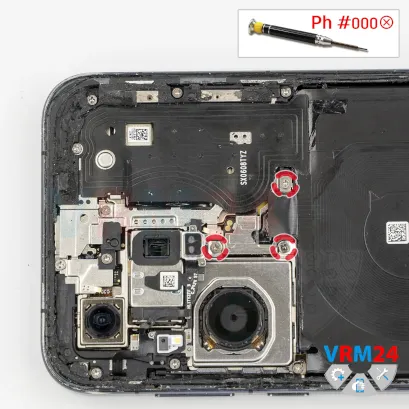
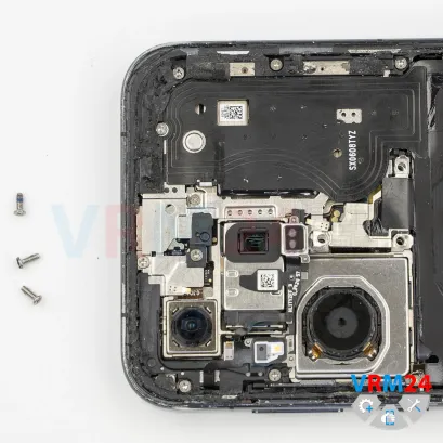
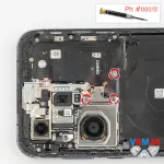
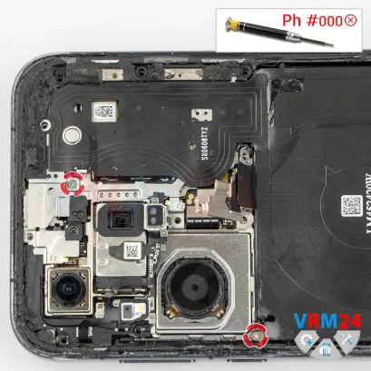
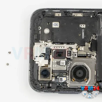
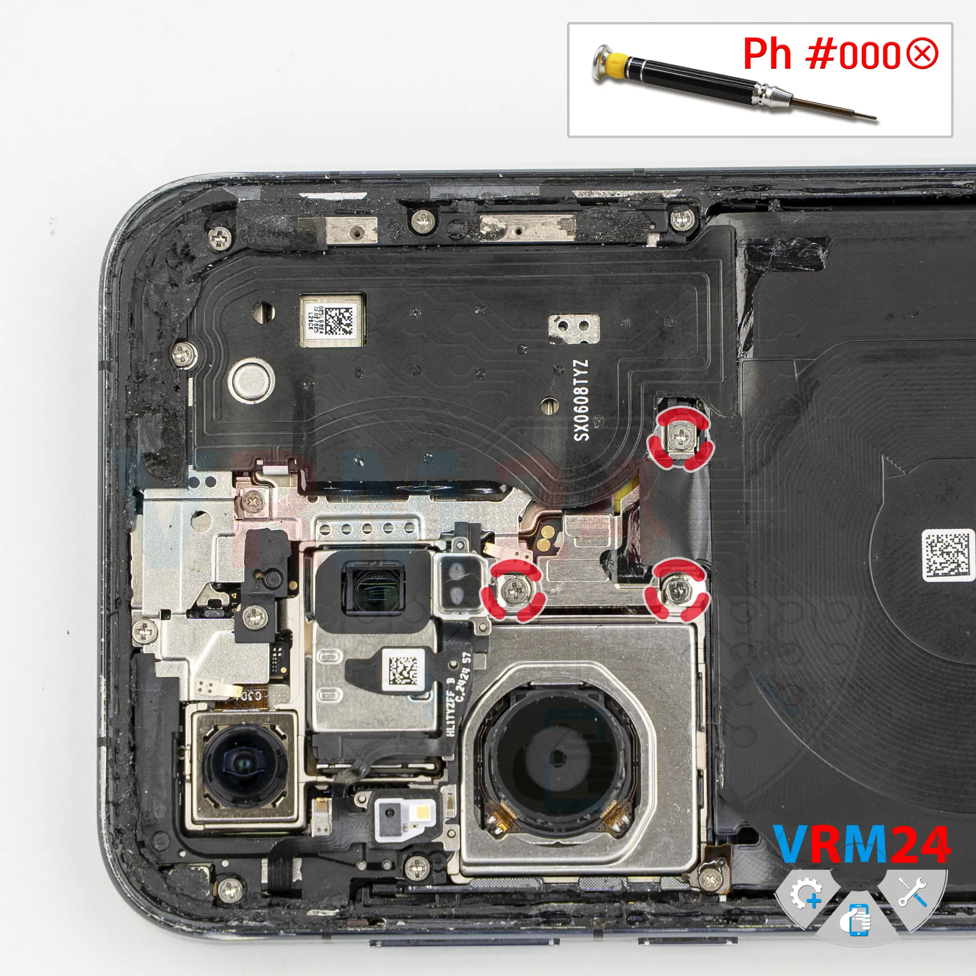
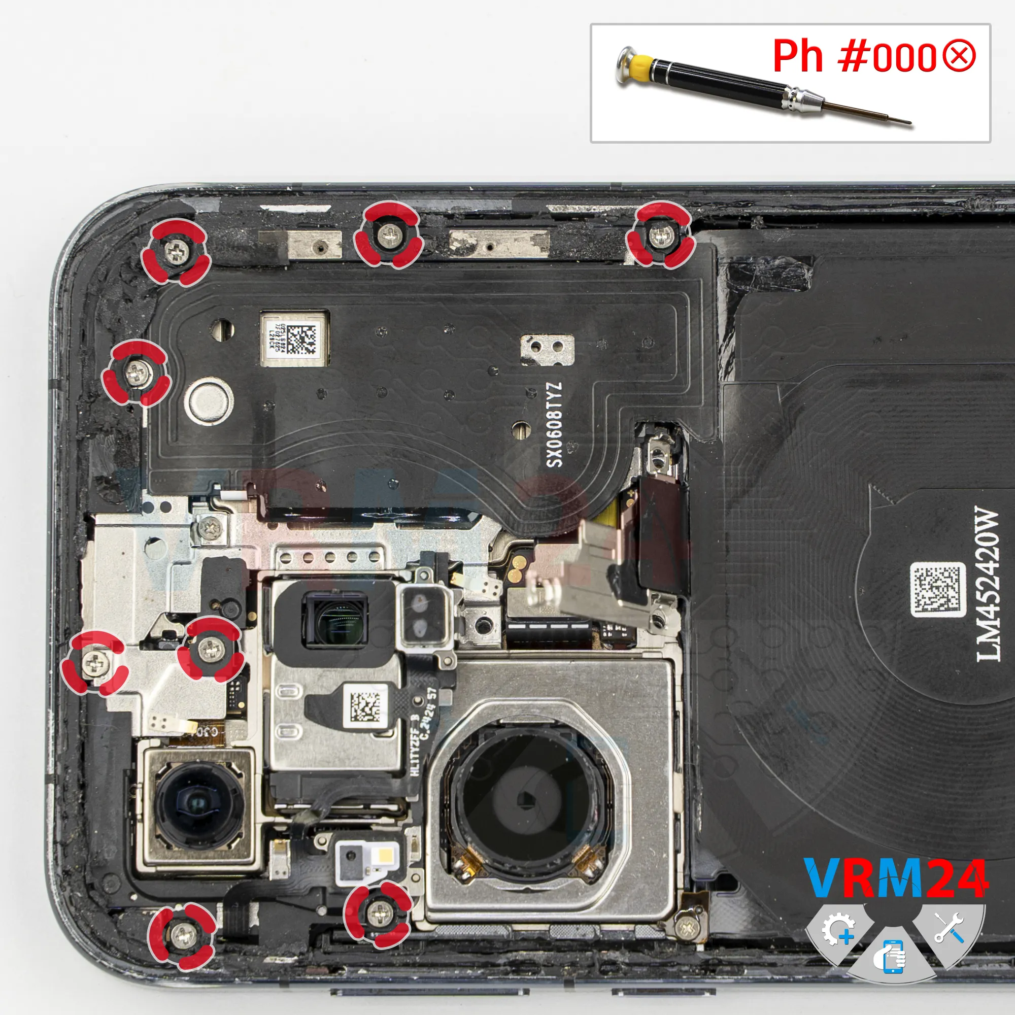
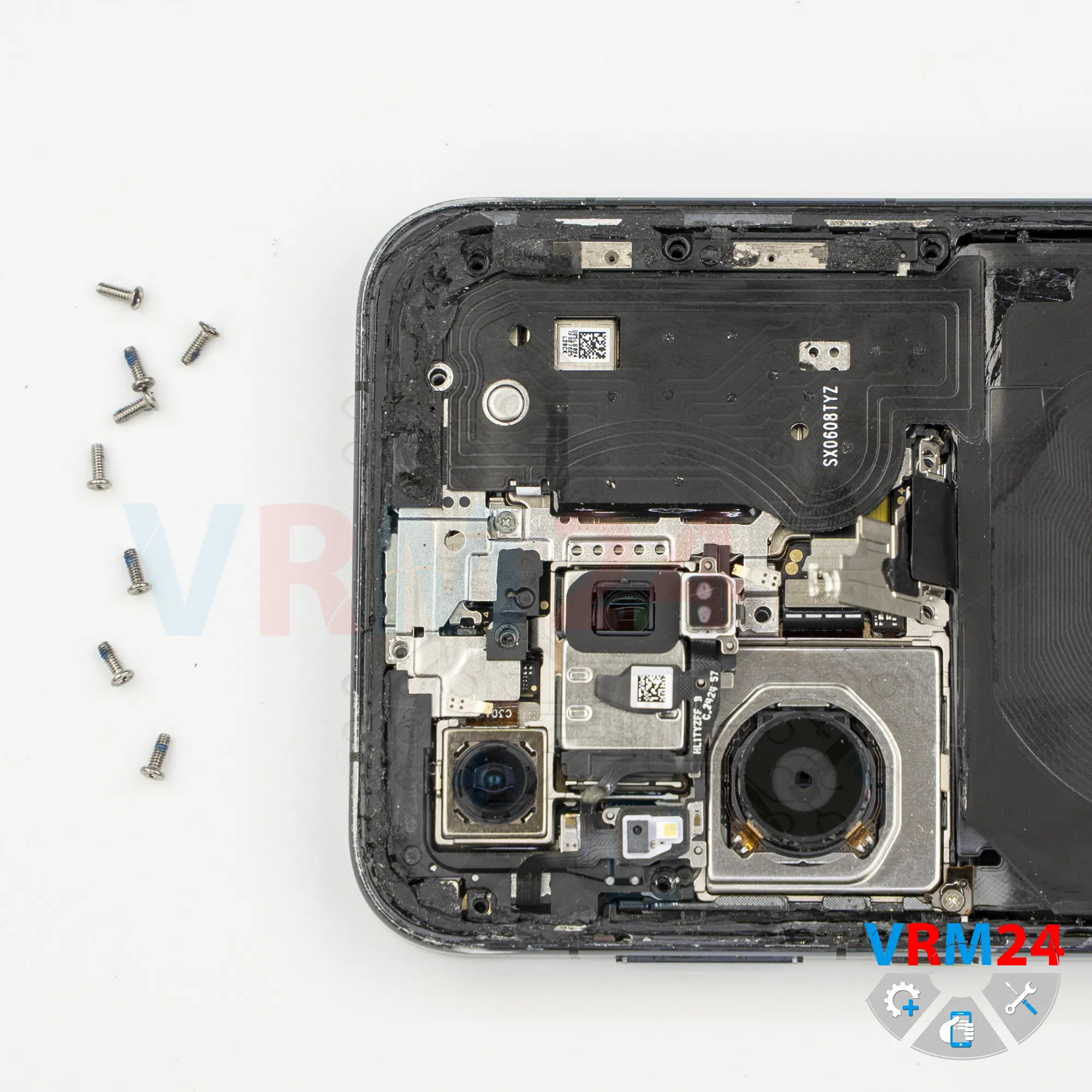
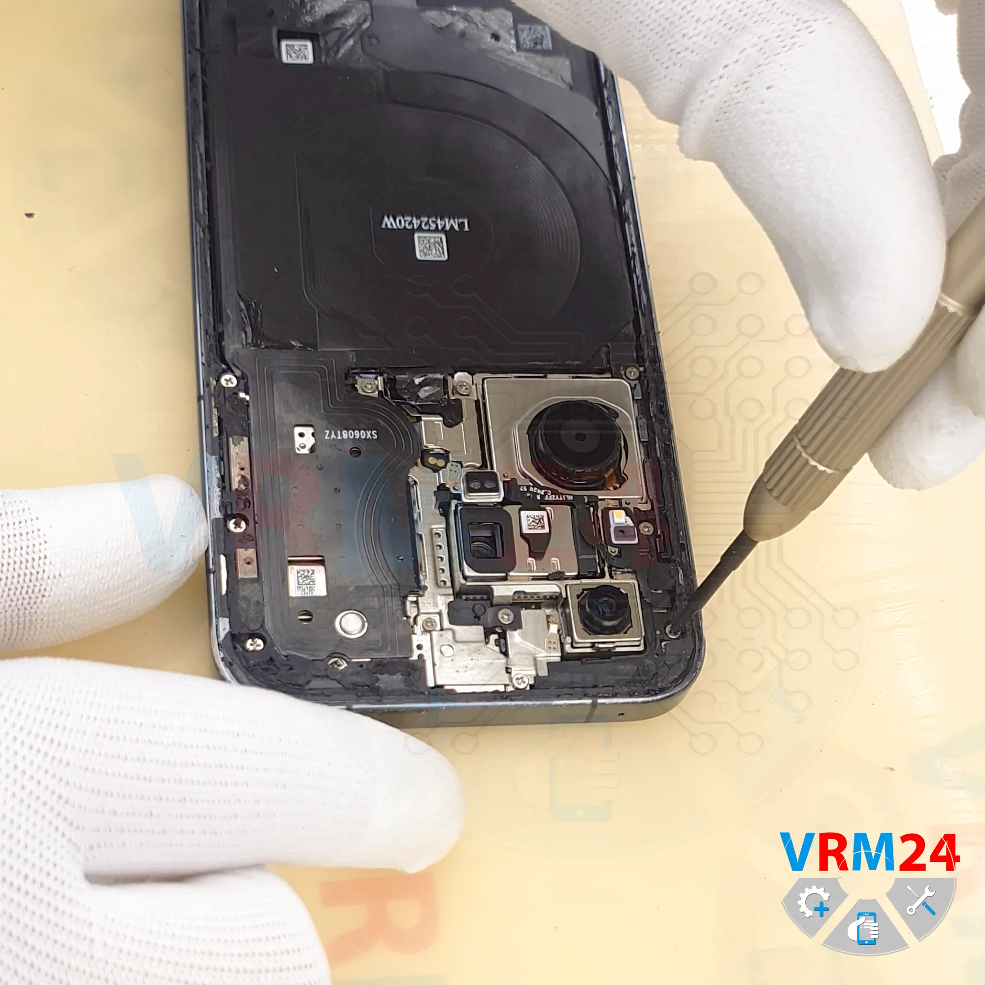
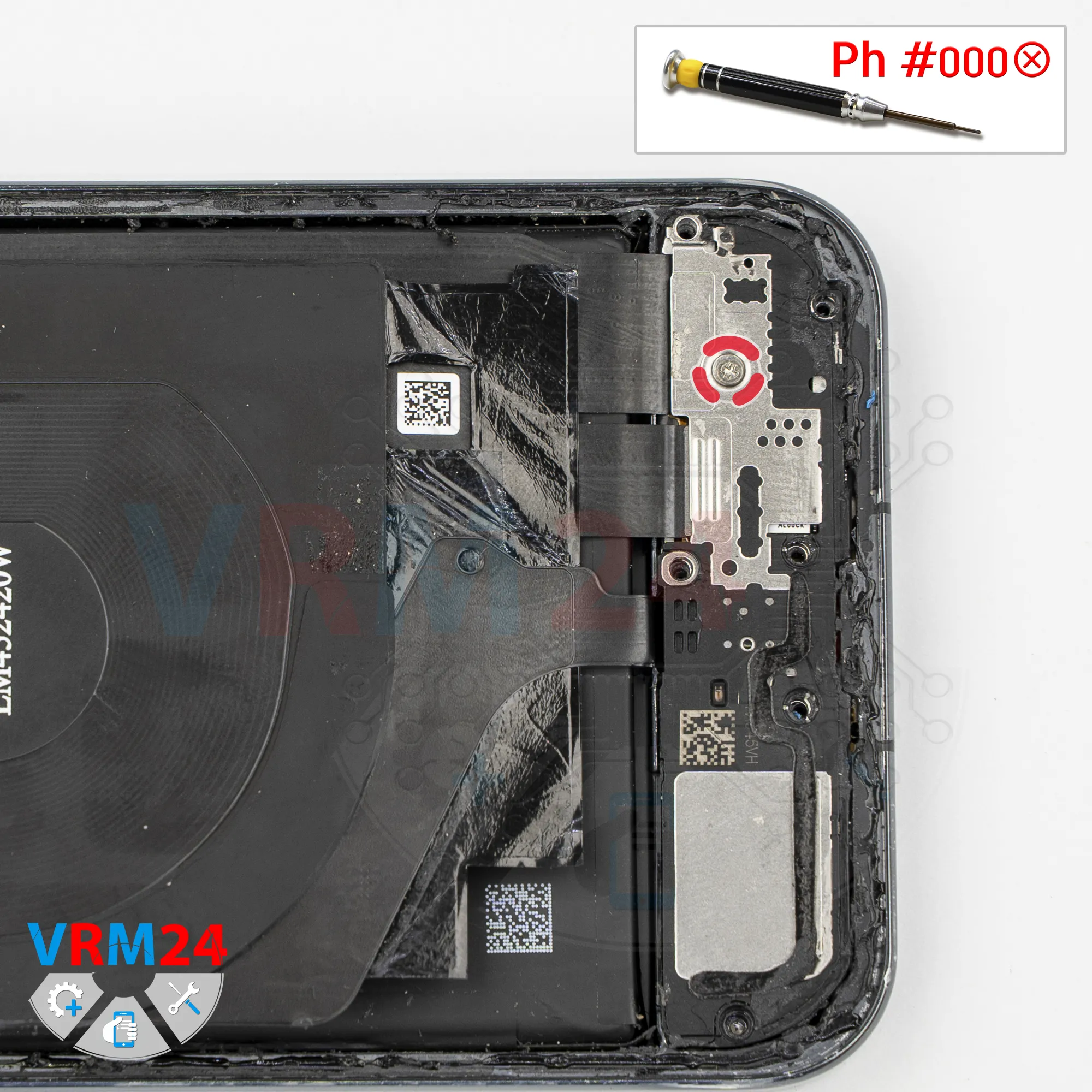
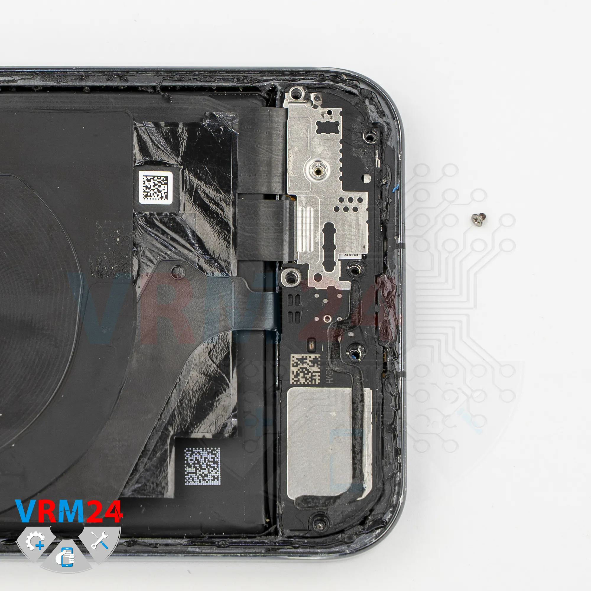
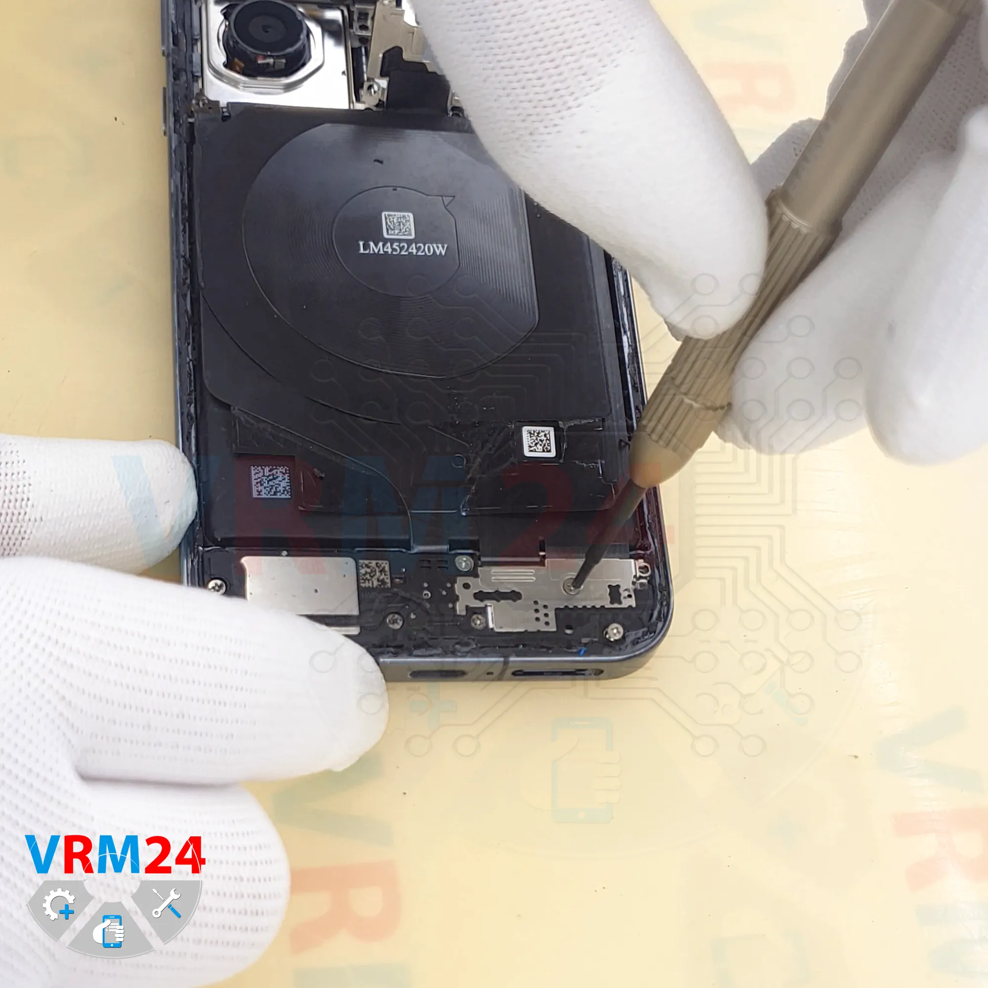
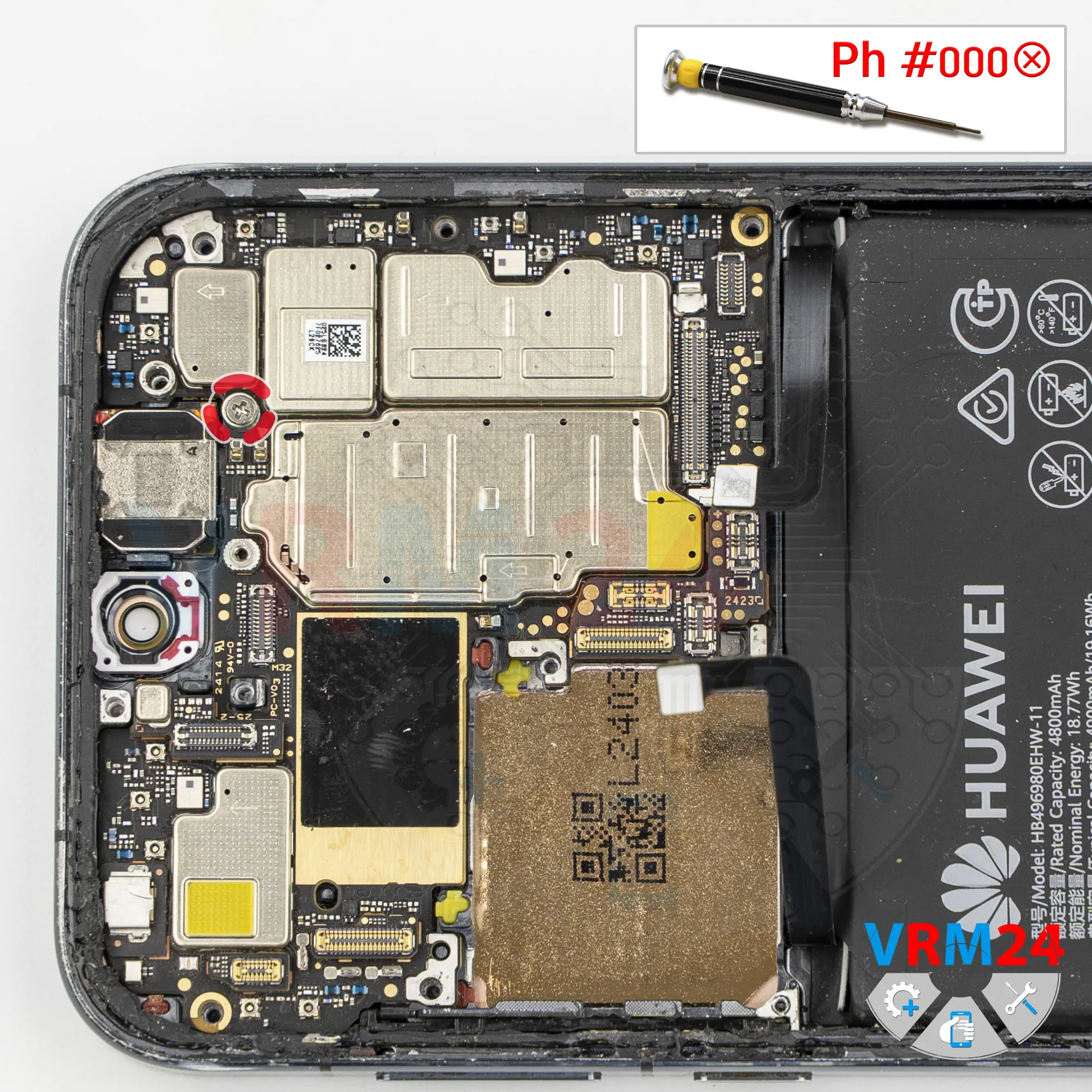
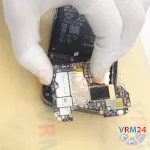
Step 18. Unscrew one screw
Now we need to remove one screw securing the motherboard, again using a Phillips #000 screwdriver.
This screw is also different from the previous ones, so it should be kept separately.
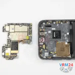
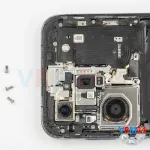
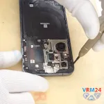
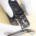
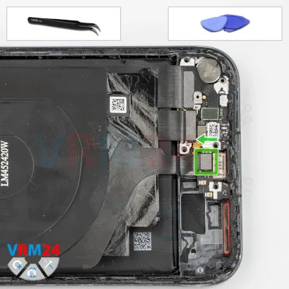
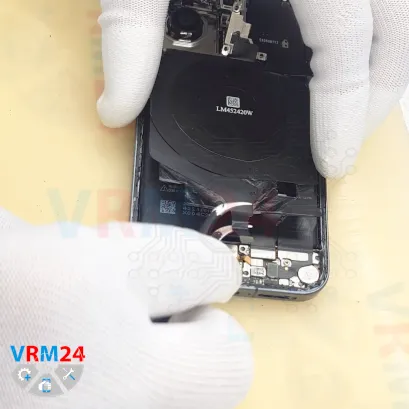
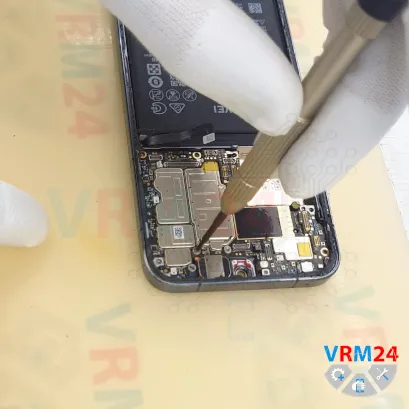
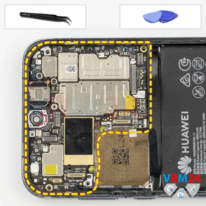
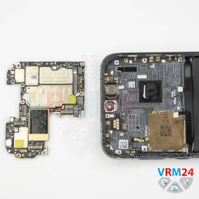
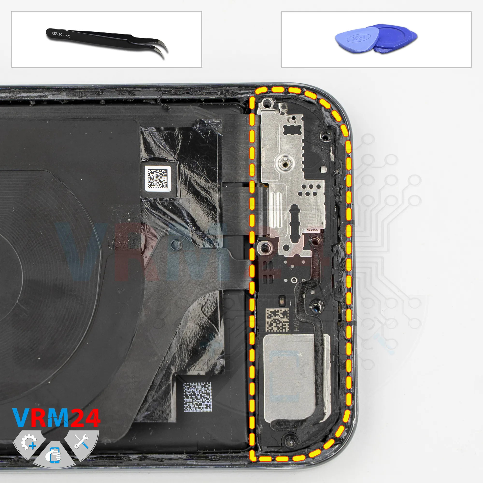
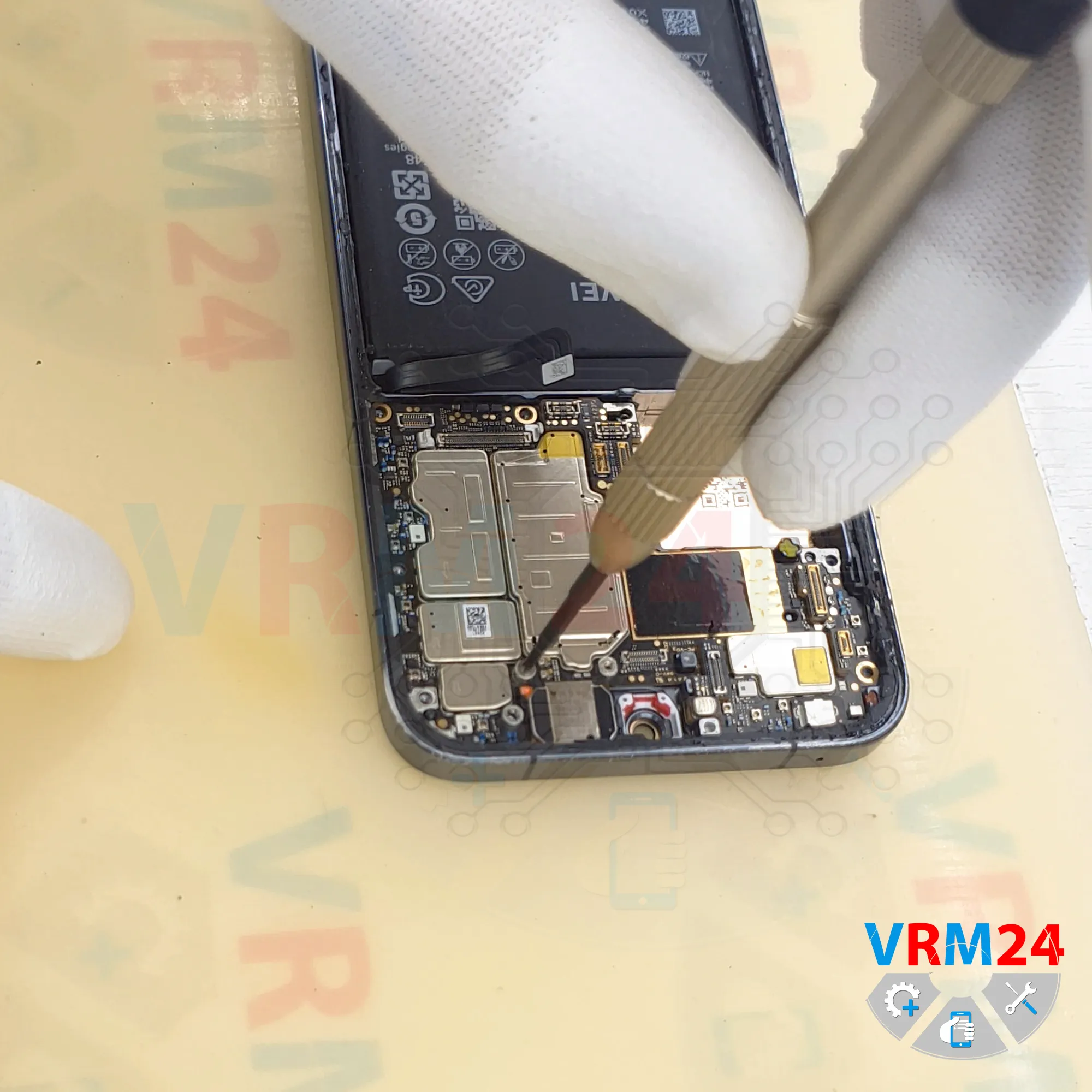
Step 19. Remove the motherboard
And now nothing is preventing us from removing the motherboard.
As before, we need to carefully lift it from the edge in the correct spot, raise it, and remove it.
On the reverse side, the motherboard may still be held in place by thermal paste.
Detailed disassembly instructions of Huawei Pura 70 in the video, made by our mobile repair & service center:
If you have a question, ask us, and we will try to answer in as much detail as possible. If this article was helpful for you, please rate it.

Disassembling\Repair has medium complexity and takes about minutes in time.
Our manual is suitable for all models Huawei Pura 70 — Huawei Pura 70 ADY-LX9 released for markets in different countries.
Back to the list