

⚠️️ Before disassembling, do not forget to turn your phone off.
Teardown difficulty:
Easy
Easy
Recommended tools


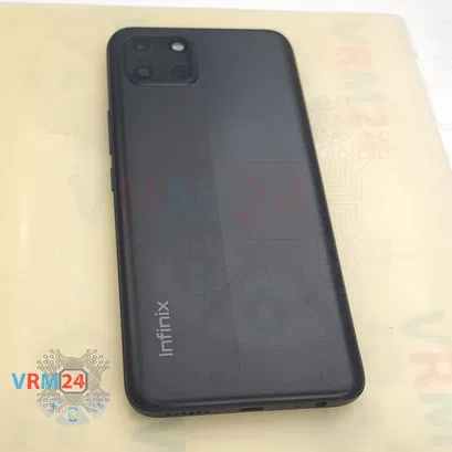
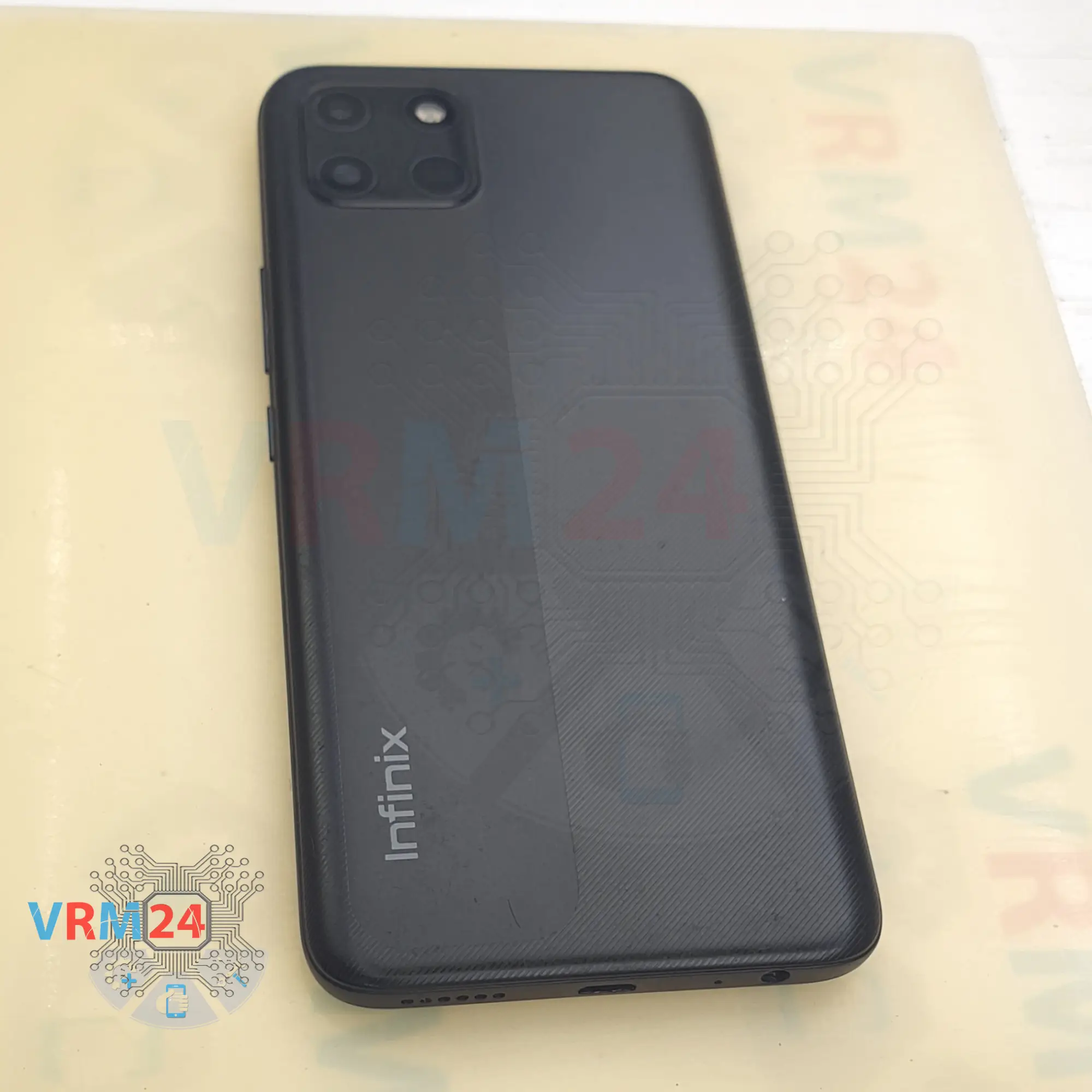
Disassembly/Repair of the mobile device Infinix Smart 6 HD with each step description and the required set of tools.


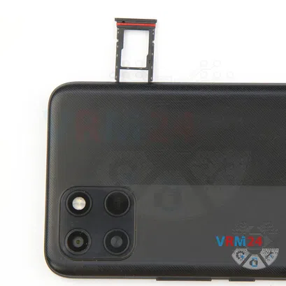
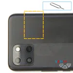
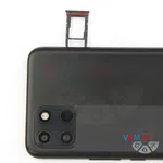
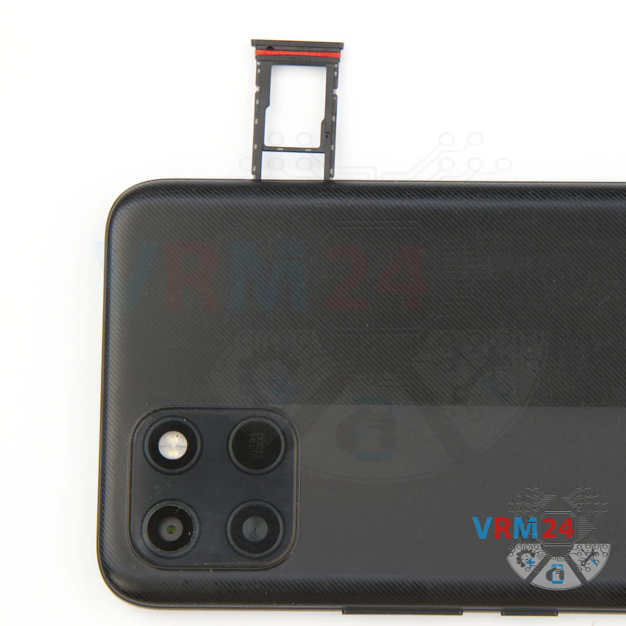
Step 2. Remove the tray
First, we need to remove the card tray. To do this, we use a special tool, insert it into the hole and carefully push out the SIM and memory card tray.

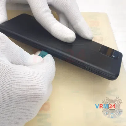
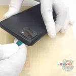

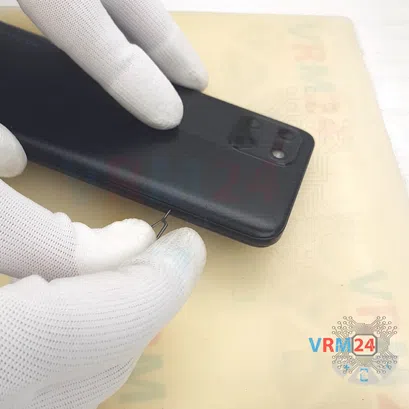
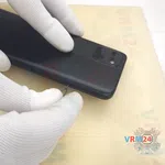
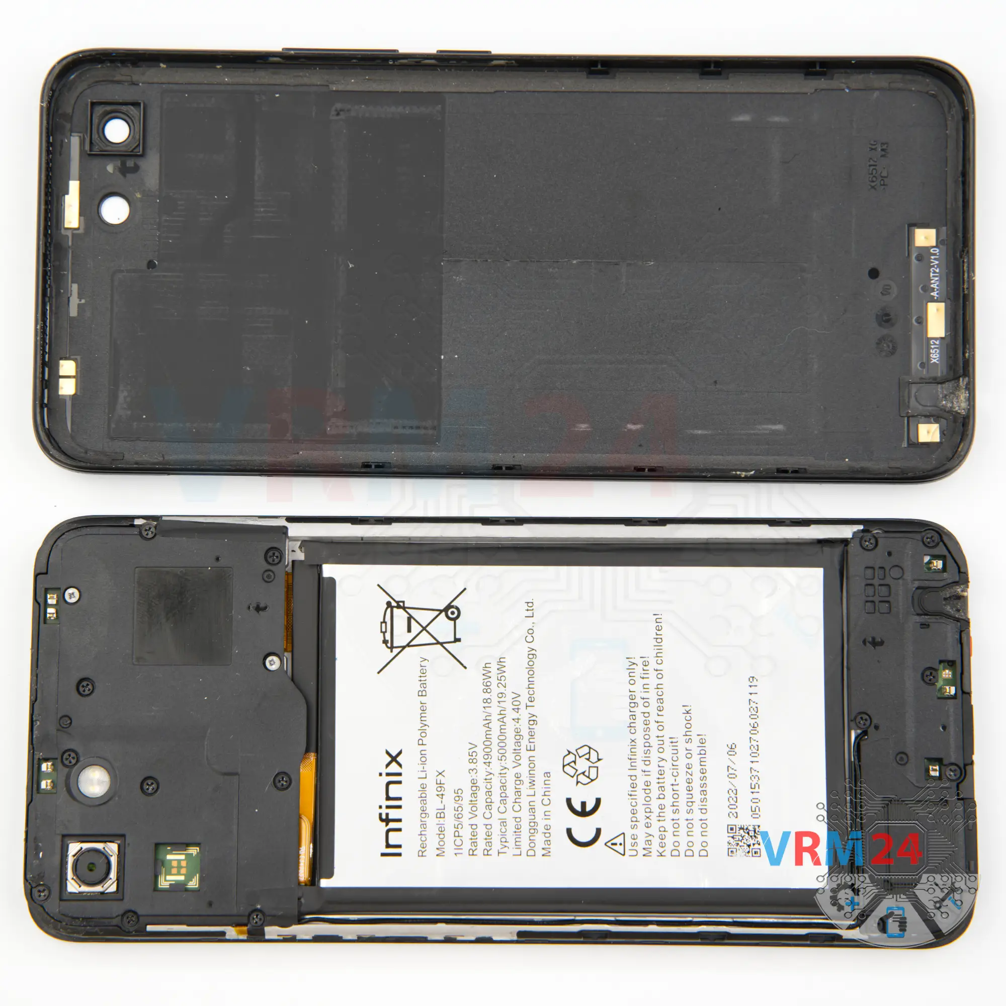
Step 3. Open the back cover
We need to detach the back cover. For this we use a plastic tool.
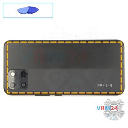
We carefully insert it into the gap between the back cover and the display frame and gently run it along the edge, detaching the back cover.
We always need to be careful around the side buttons, as they are physically located in these places, and we also need to be careful on the corners, as the cover is held tightly on the corners.
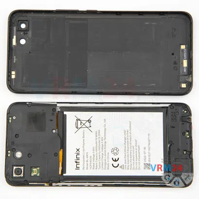
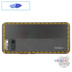
On the back cover, we have the antenna contact pads.

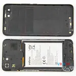
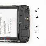
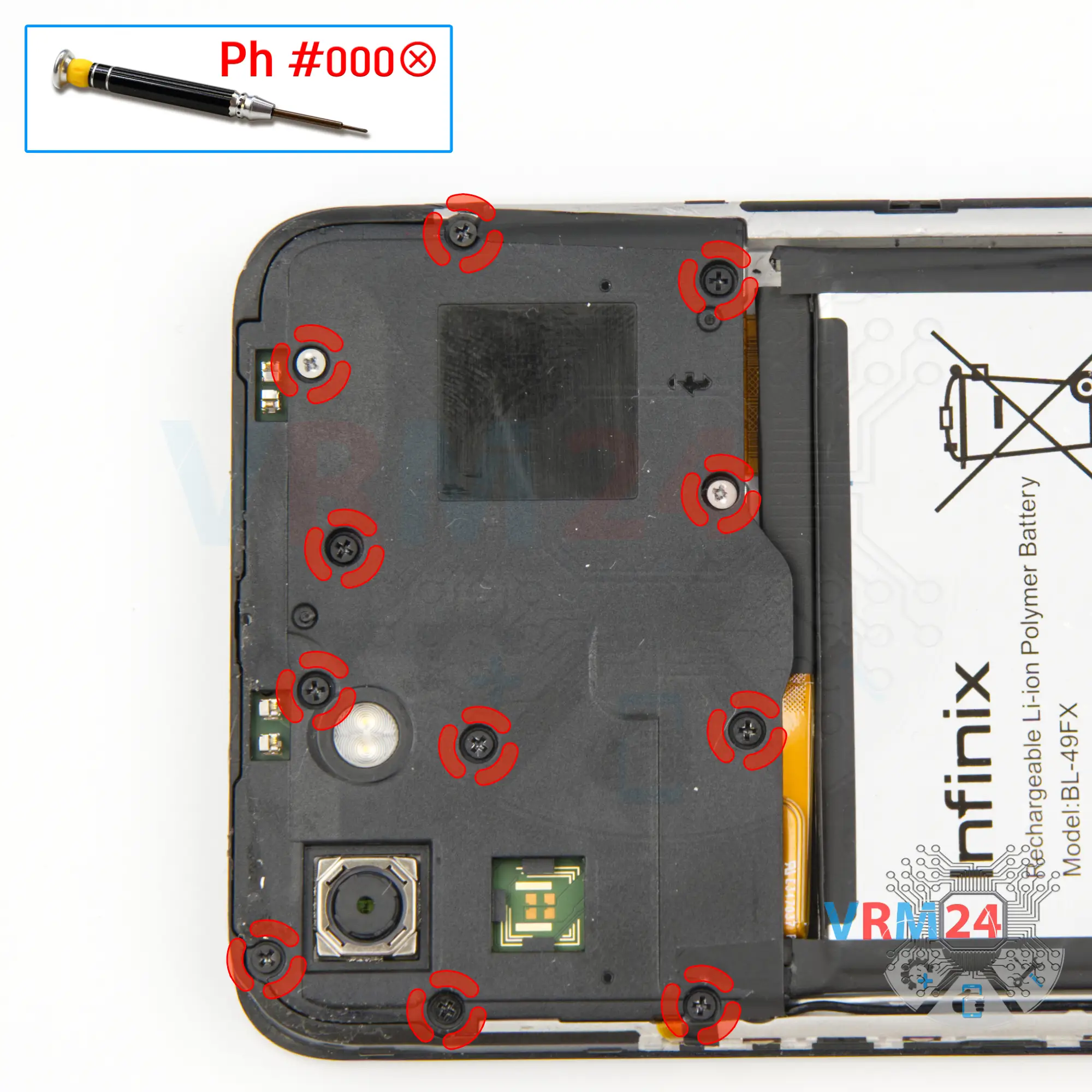
Step 4. Unscrew the screws
We move on to removing the screws at the top. For this we use a 1.5mm Phillips screwdriver or a Philips #000.
Please note that the screws we have are different, so it is better to place them on a special surface in a certain order, so as not to confuse anything when reassembling.


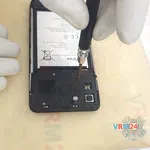
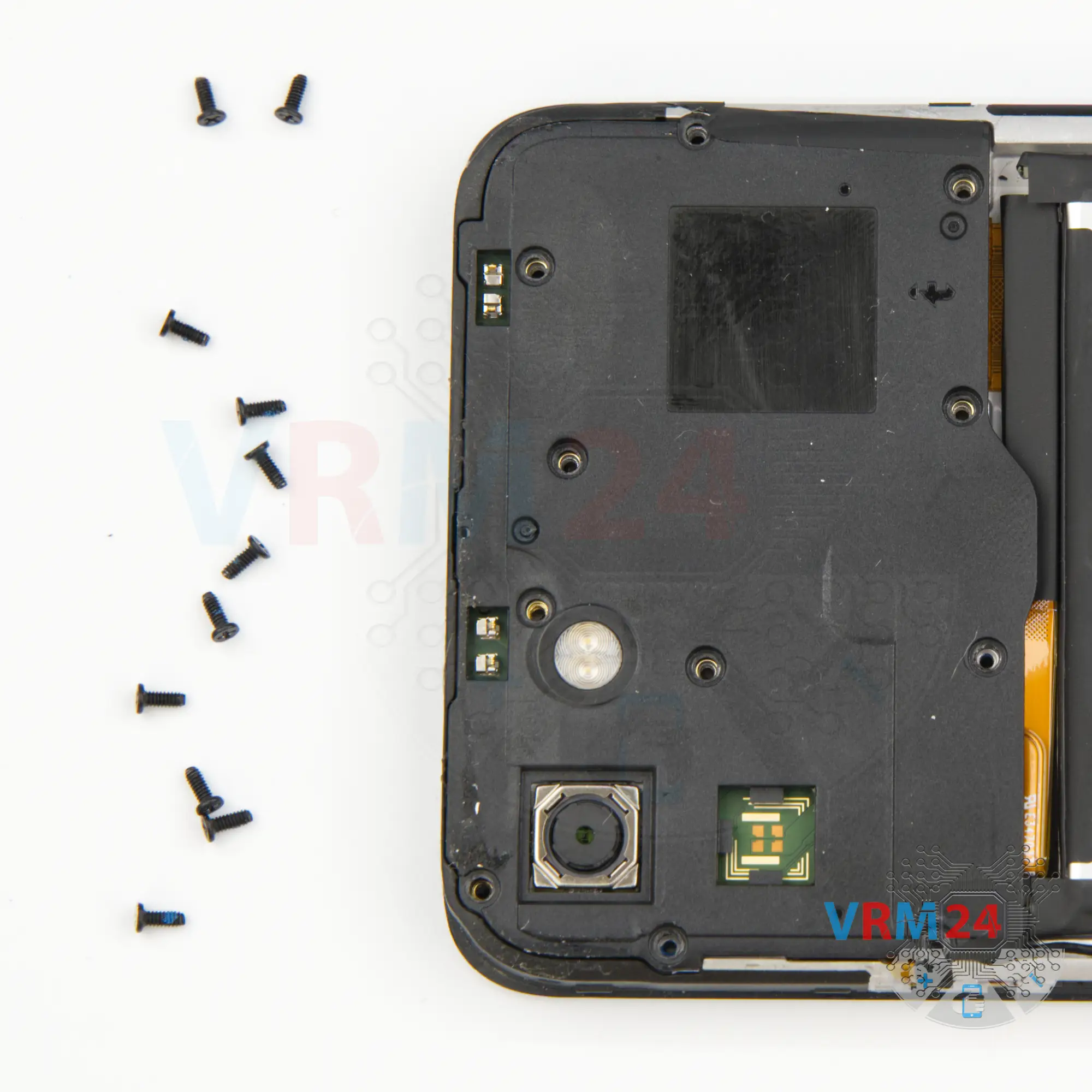
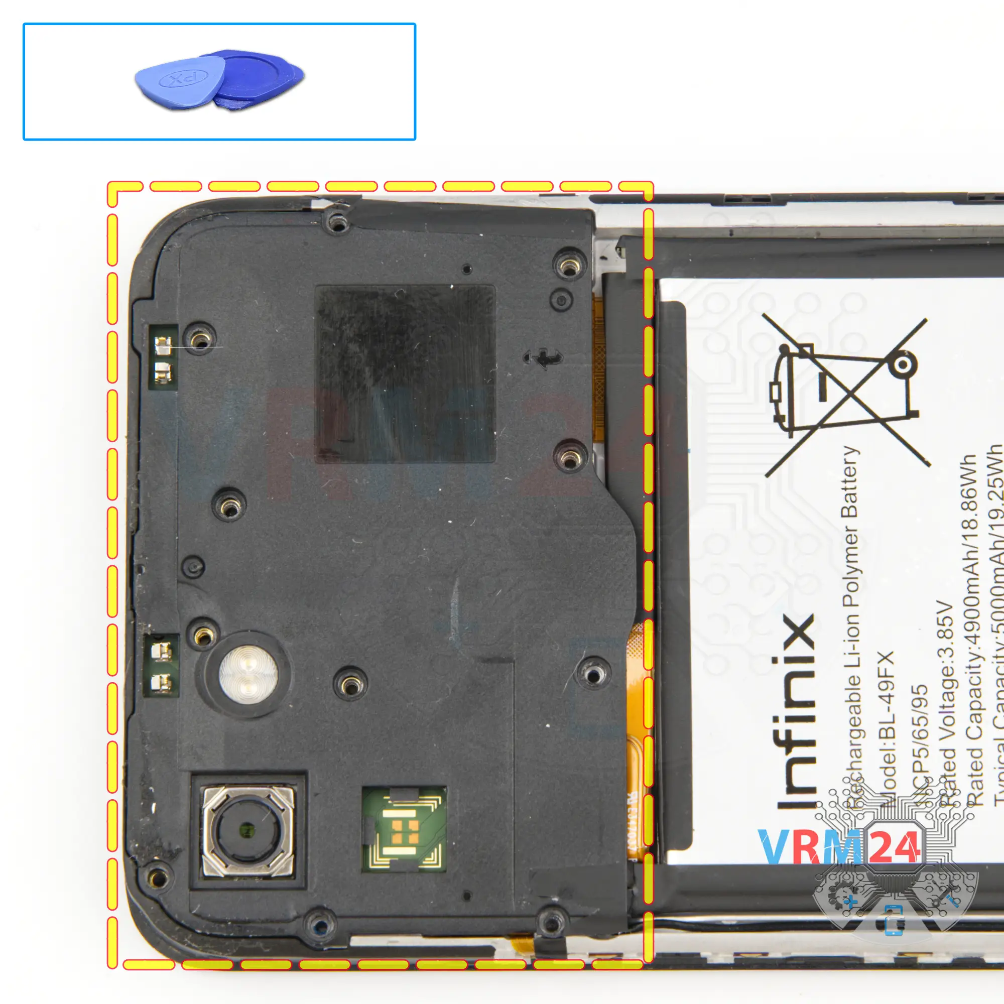
Step 5. Open the cover
So, after removing the screws, we need to detach the cover at the top. To do this, we use a non-metallic tool.
Carefully pry in the right place, lift and try to detach the cover.
The cover turned out to be also glued on one side with tape. Unstick the cover and carefully remove the cover.


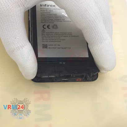
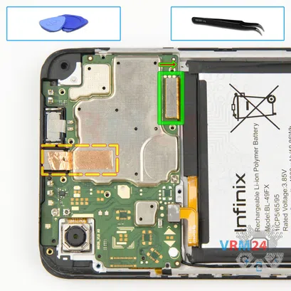
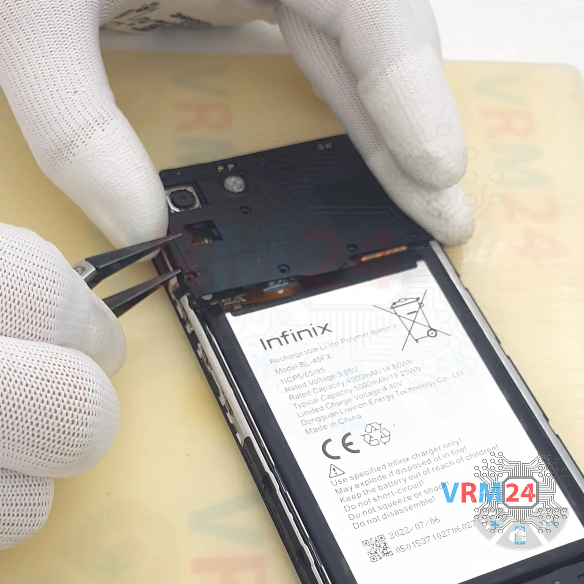
Step 6. Disconnect the battery connector
Disconnect the battery connector as soon as you can. Use a non-metallic or plastic tool to avoid any damage.
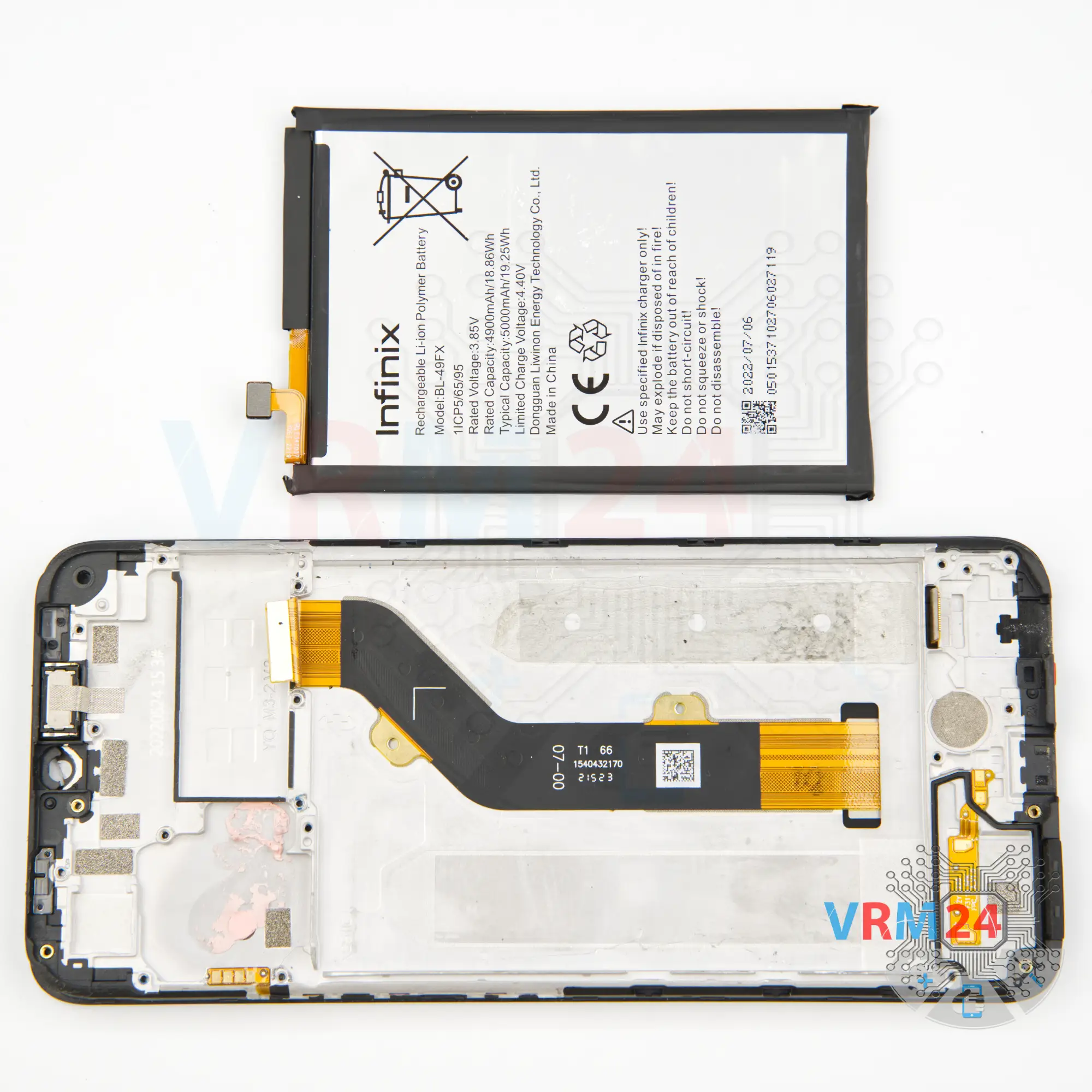
ℹ️️ The Infinix Smart 6 HD model has a battery BL-49FX with a capacity of 5000 mAh (also known as a rechargeable battery).


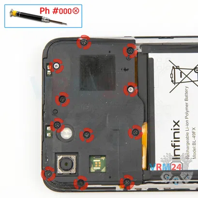
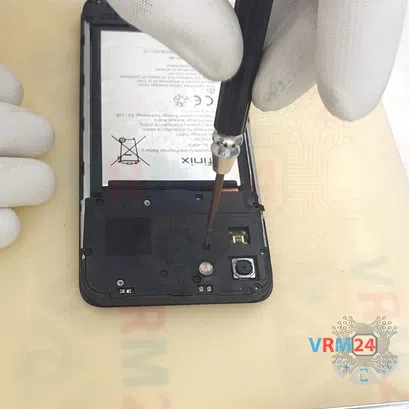
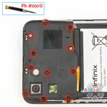
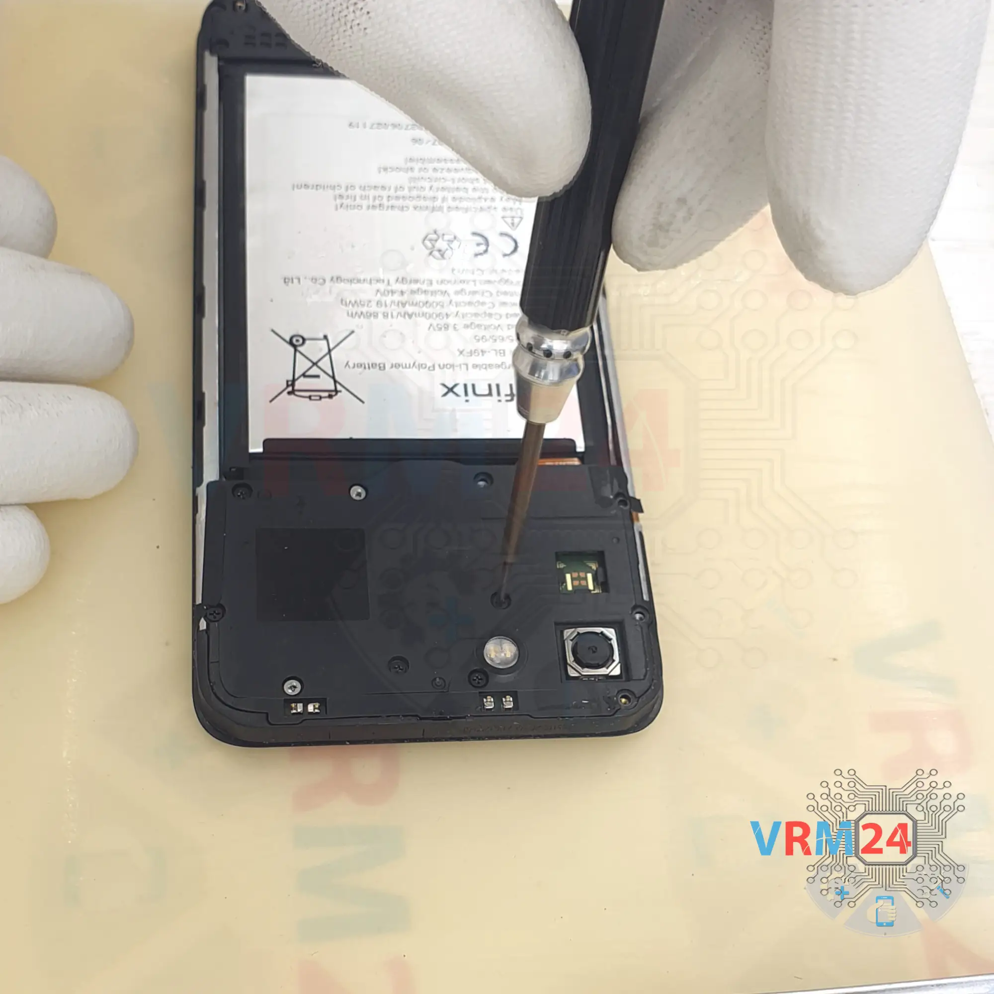
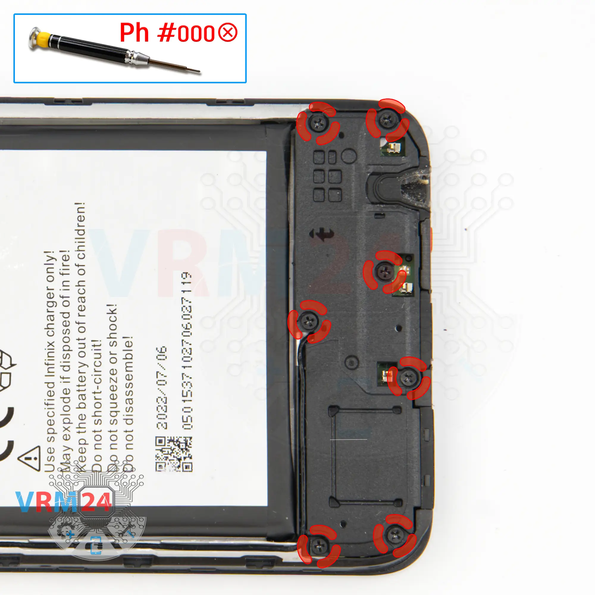
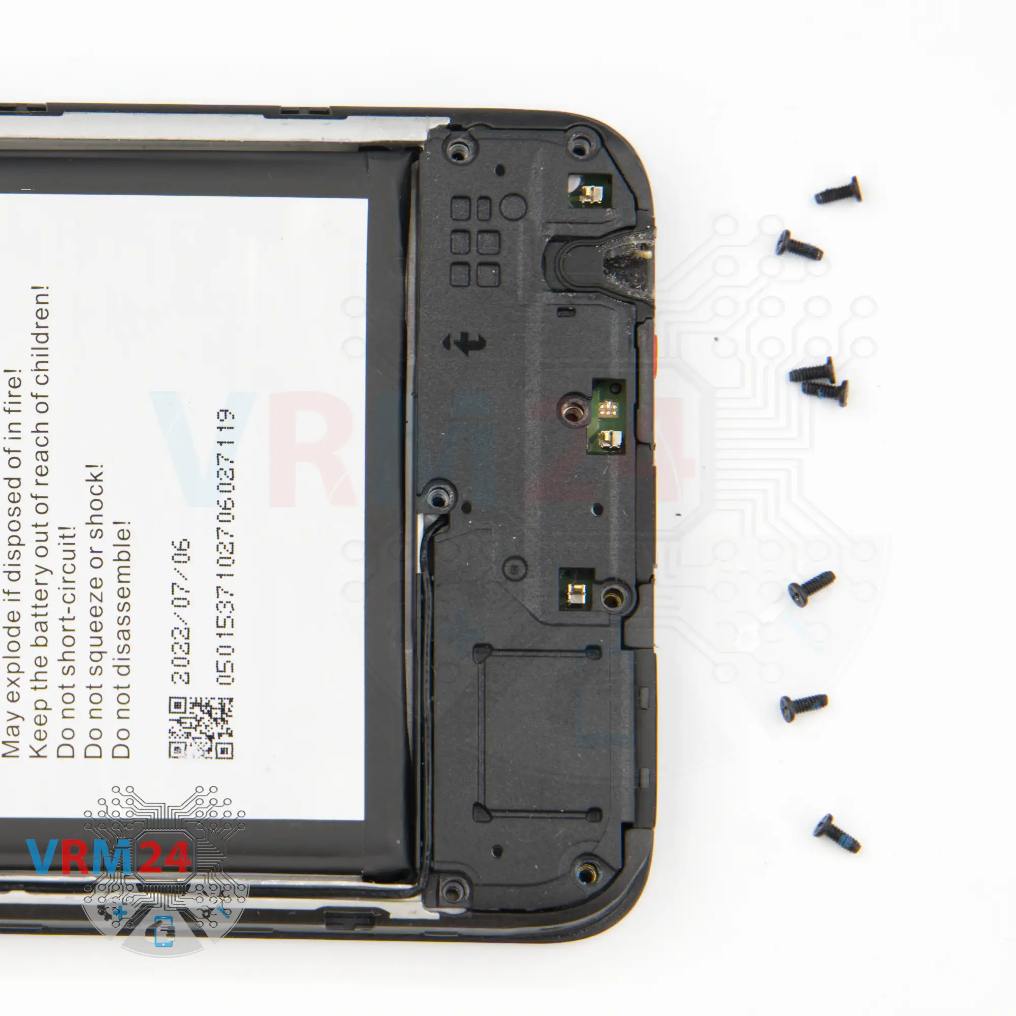
Step 7. Unscrew the screws
We move on to unscrewing the seven screws at the bottom. We use 1.5mm Phillips screwdriver or a Philips #000.
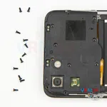
The screws at the bottom may be different from the screws at the top, so we also recommend that they are placed on a special surface and in a specific order.

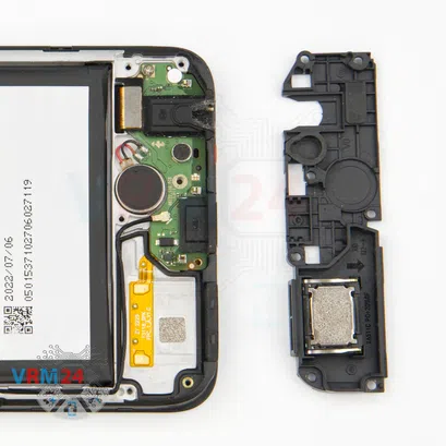

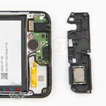
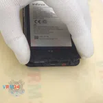
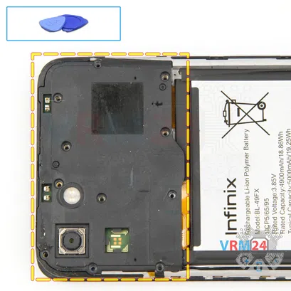
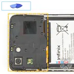
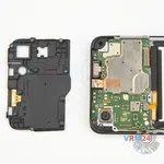
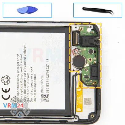
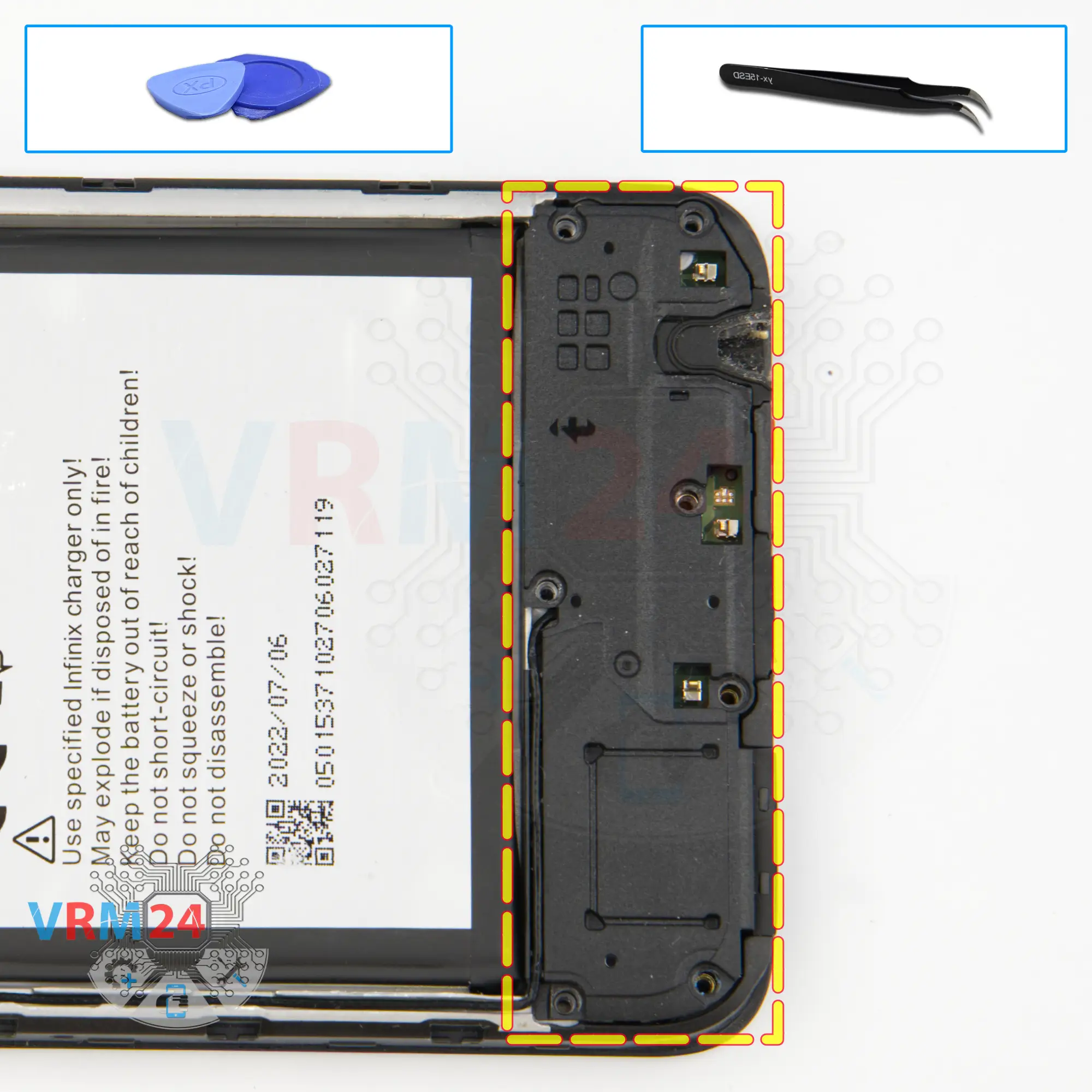
Step 8. Remove the loudspeaker
Then we can detach the cover with the loudspeaker. We remove the cover and put it aside.

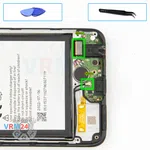
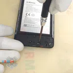
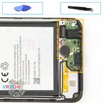
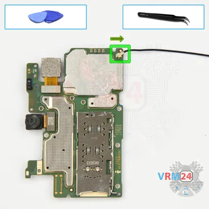
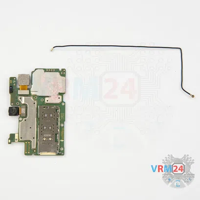
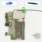
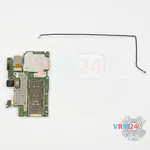
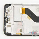
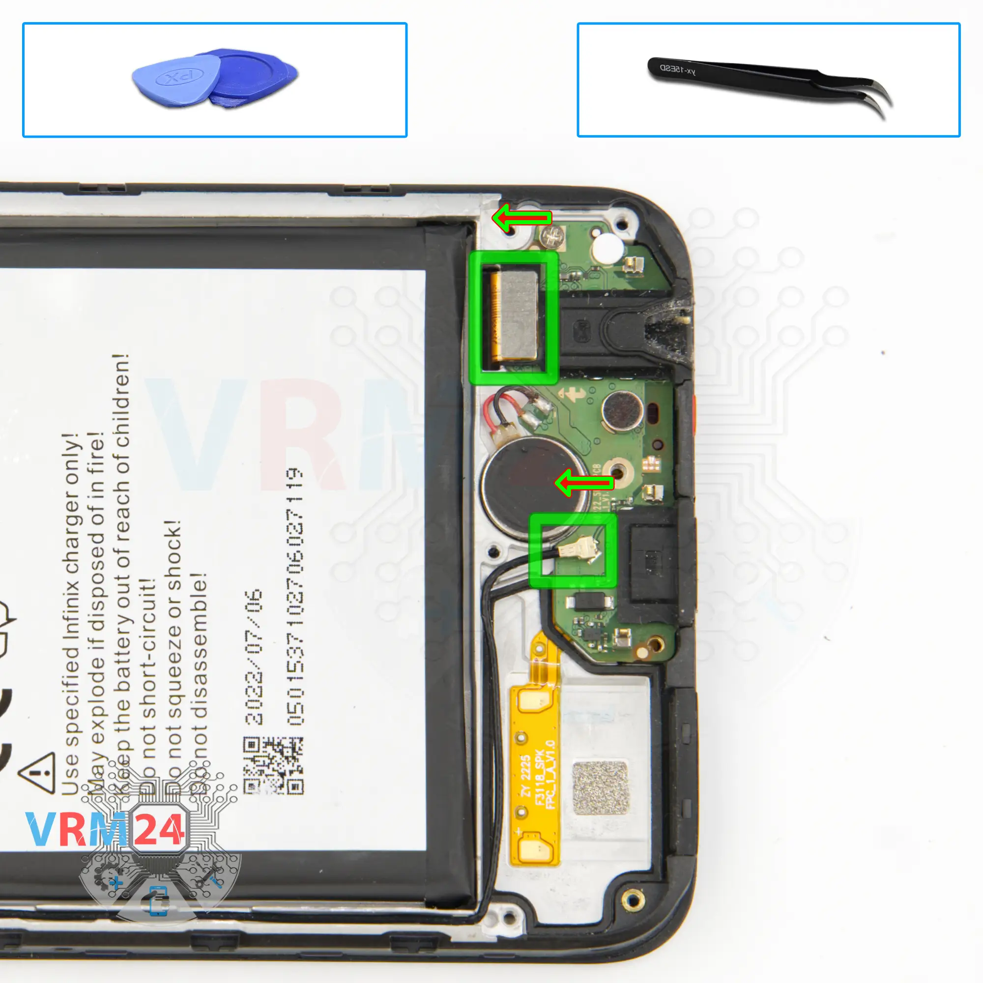
Step 9. Disconnect the connectors
We can disconnect the coaxial cable connector and inter-board cable connector on the sub-board.
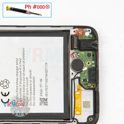
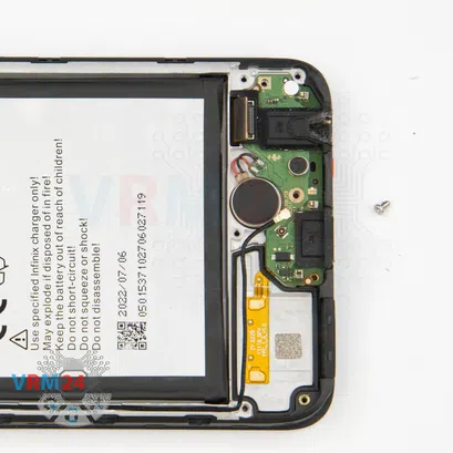
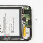
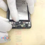
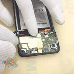
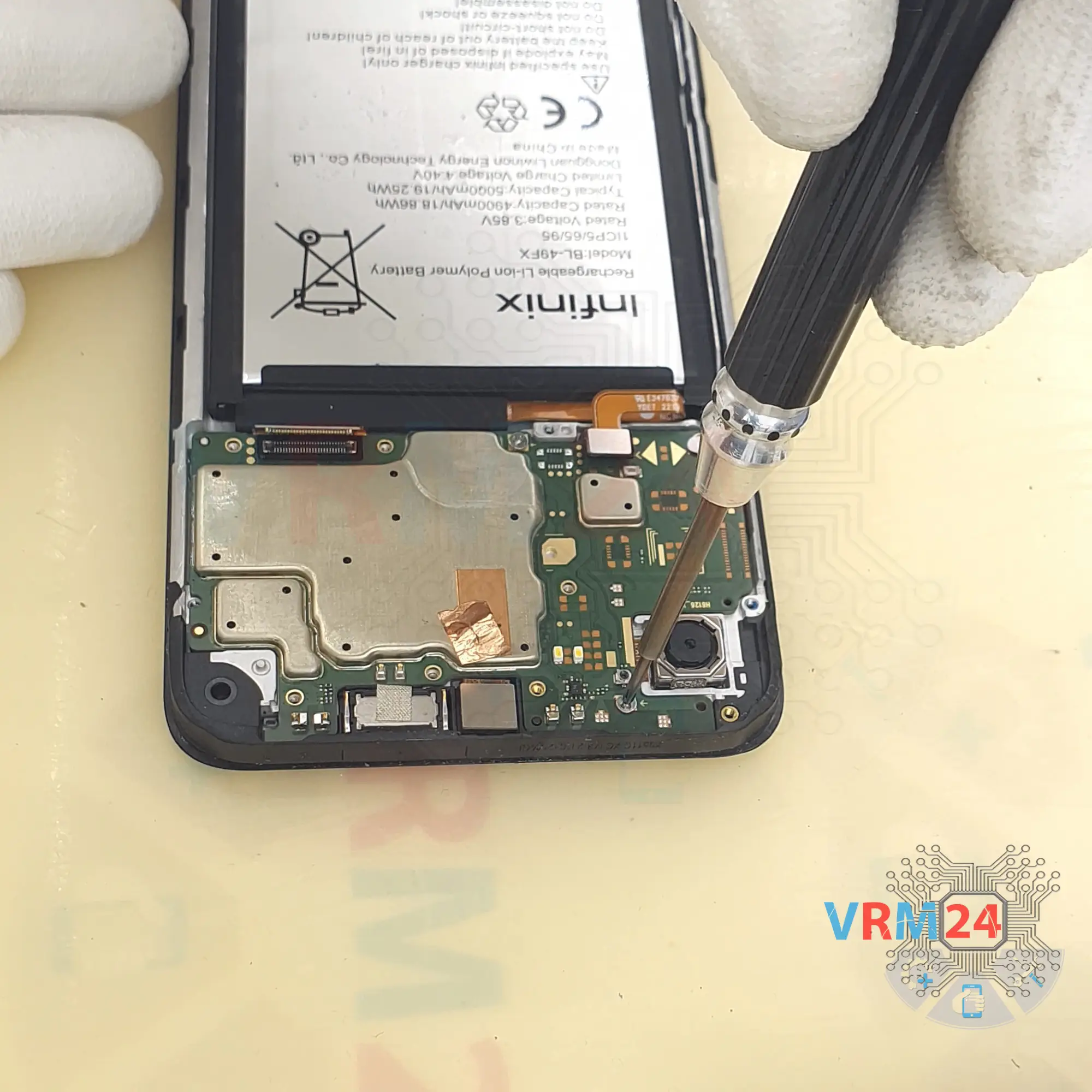
Step 10. Unscrew one screw
We need to unscrew one screw that holds the sub-board. For this we use a one and a half millimeter Phillips screwdriver. The screw we have is different from the previous ones.

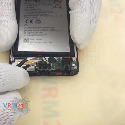
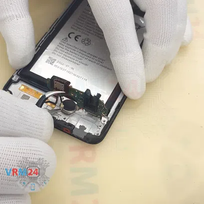

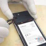
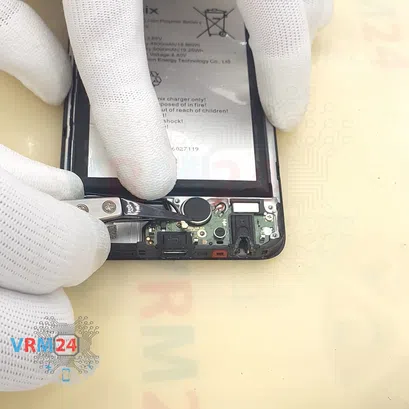
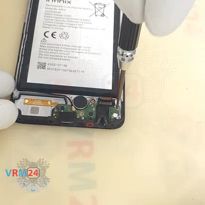
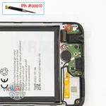
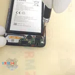
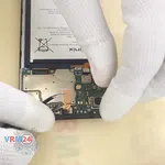
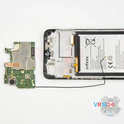
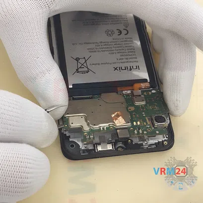
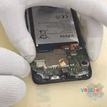
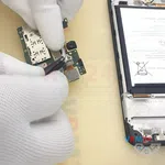
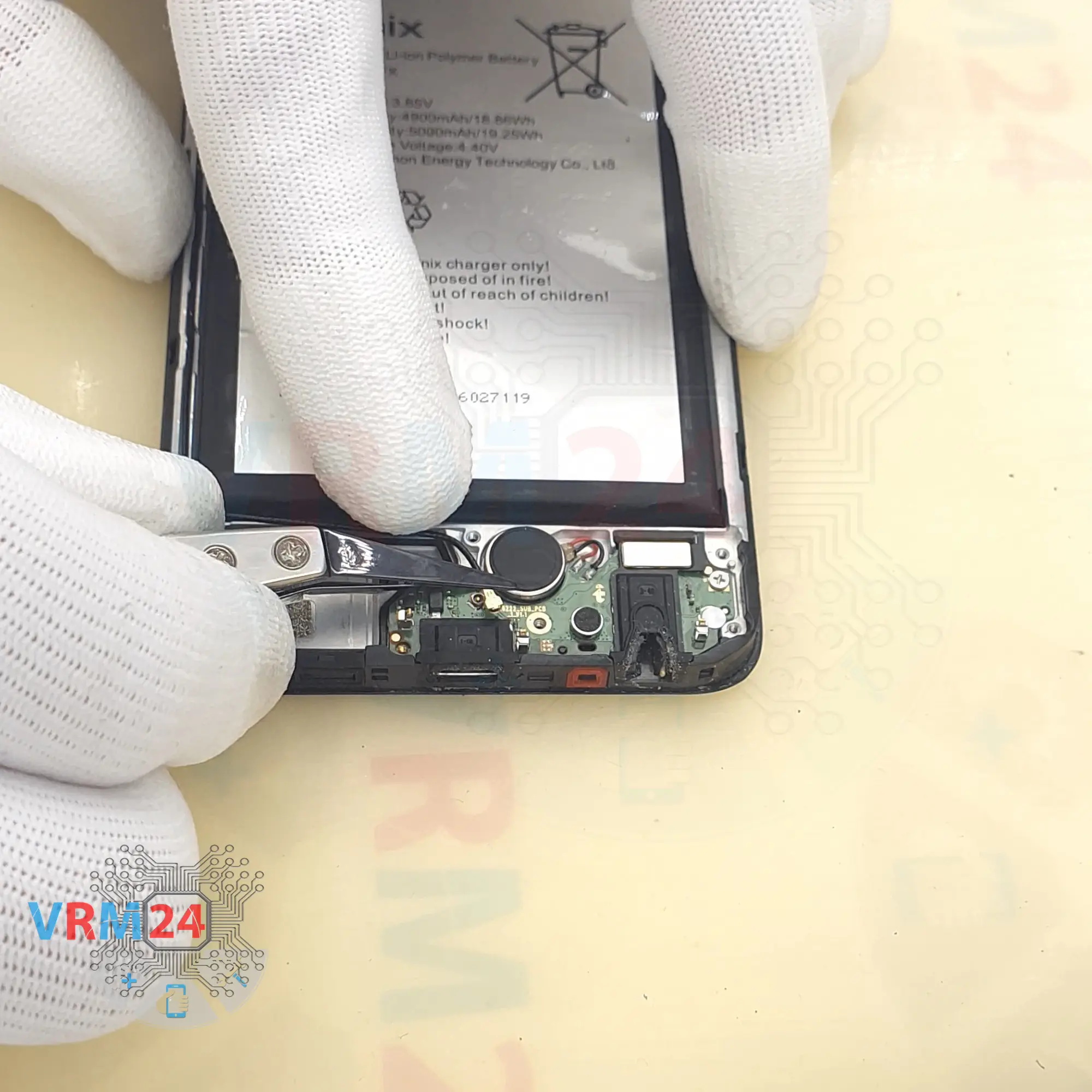
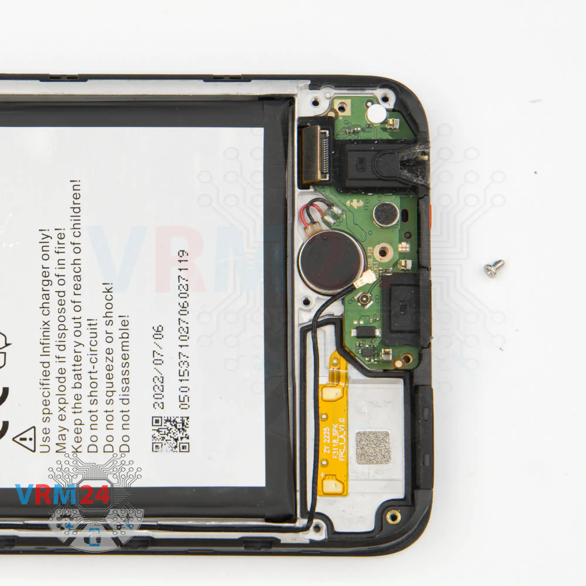
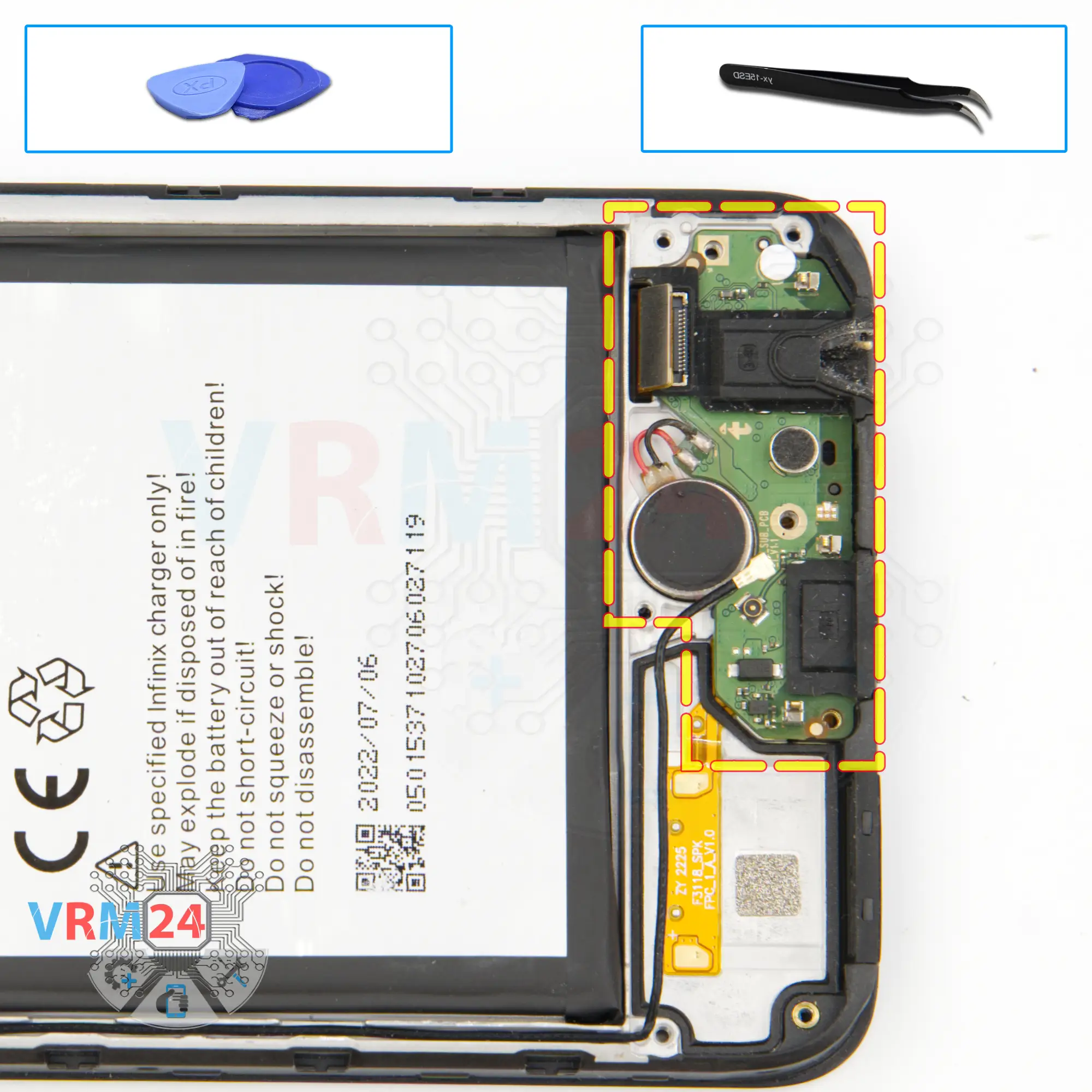
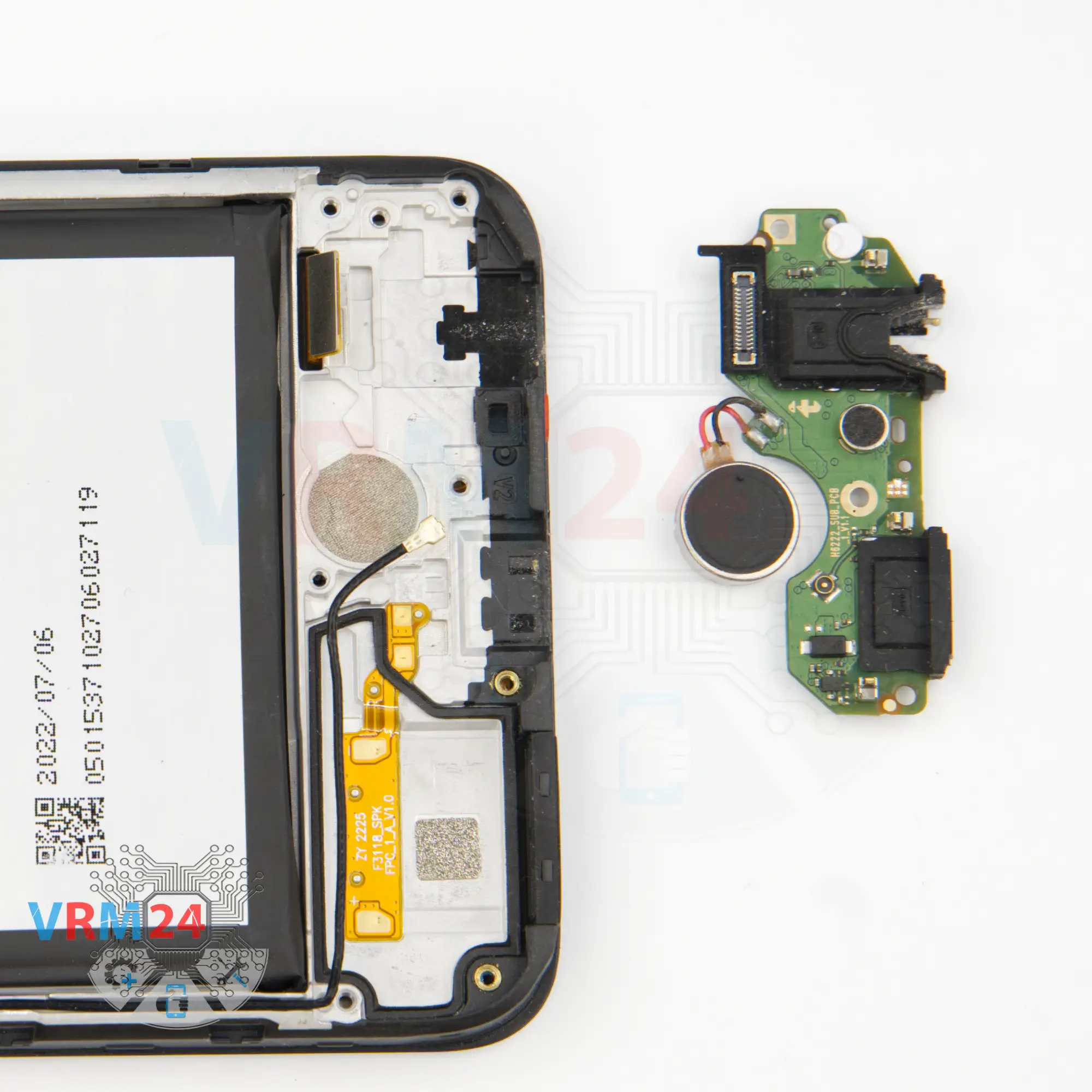
Step 11. Remove the sub-board
After that, we can detach the sub-board. We find the right place, pry it up, carefully lift the sub-board, and turn it over.
And as we can notice we need to detach the vibration motor which is glued with tape to the display frame and wired to the sub-board.
On the sub-board we have a charging port, microphone, headset jack port, vibration motor and other elements on the back side.


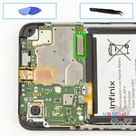
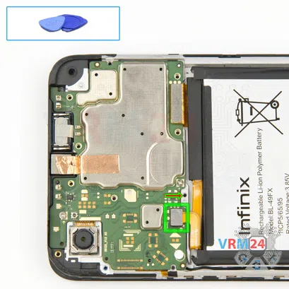
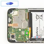
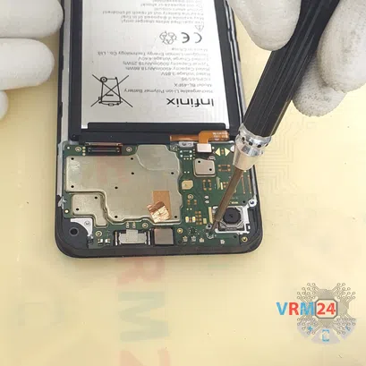
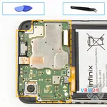
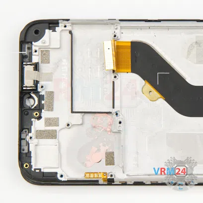
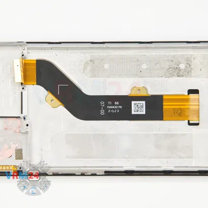
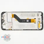
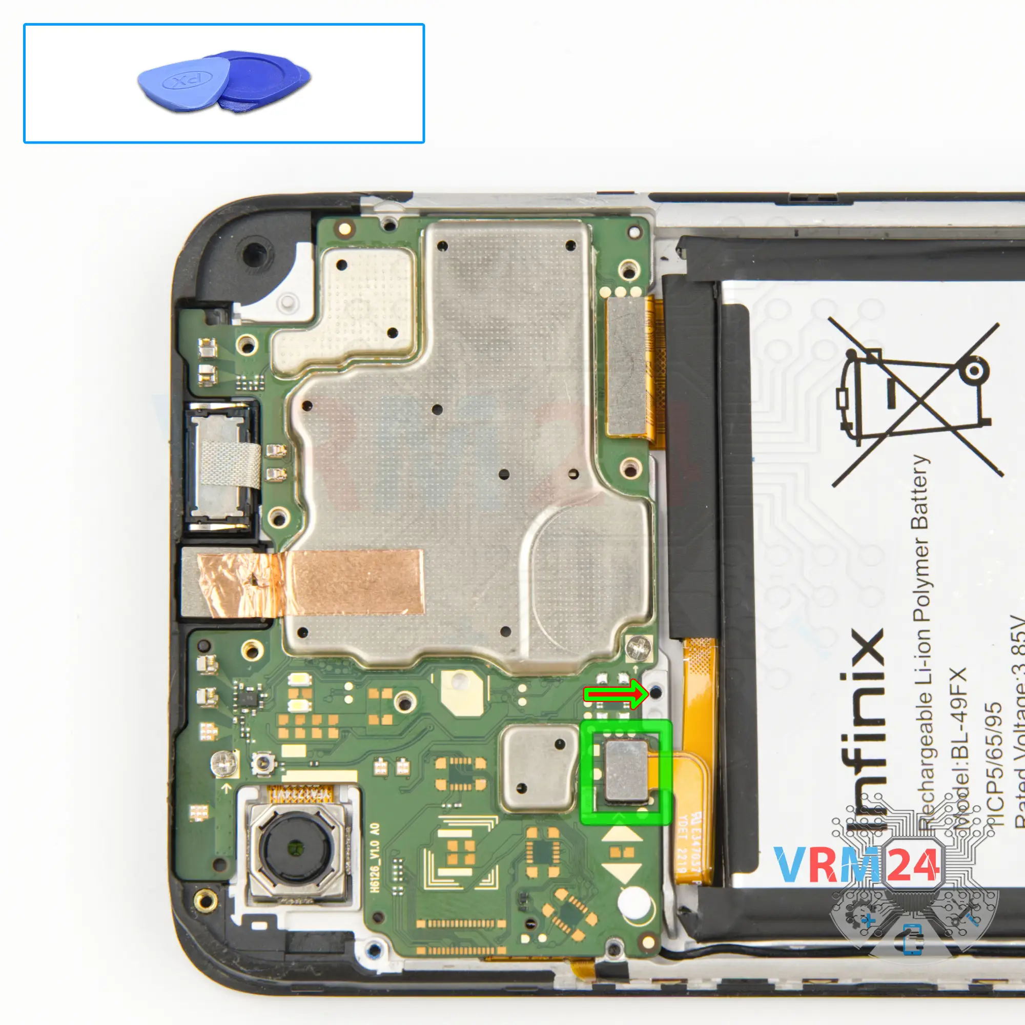
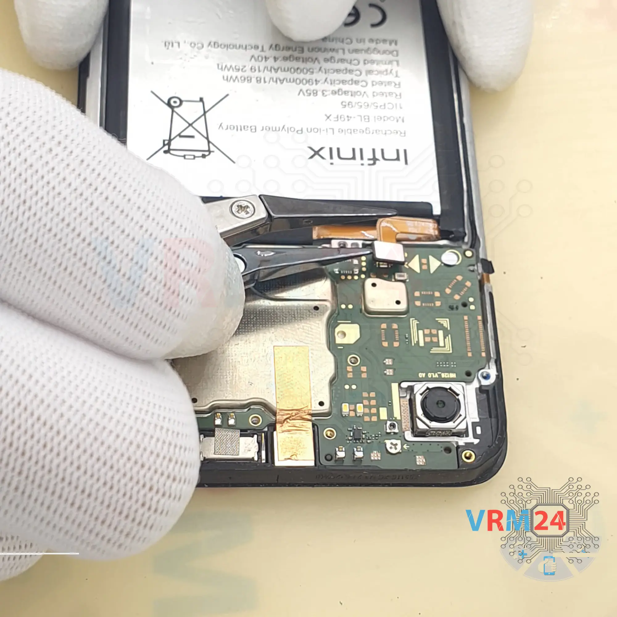
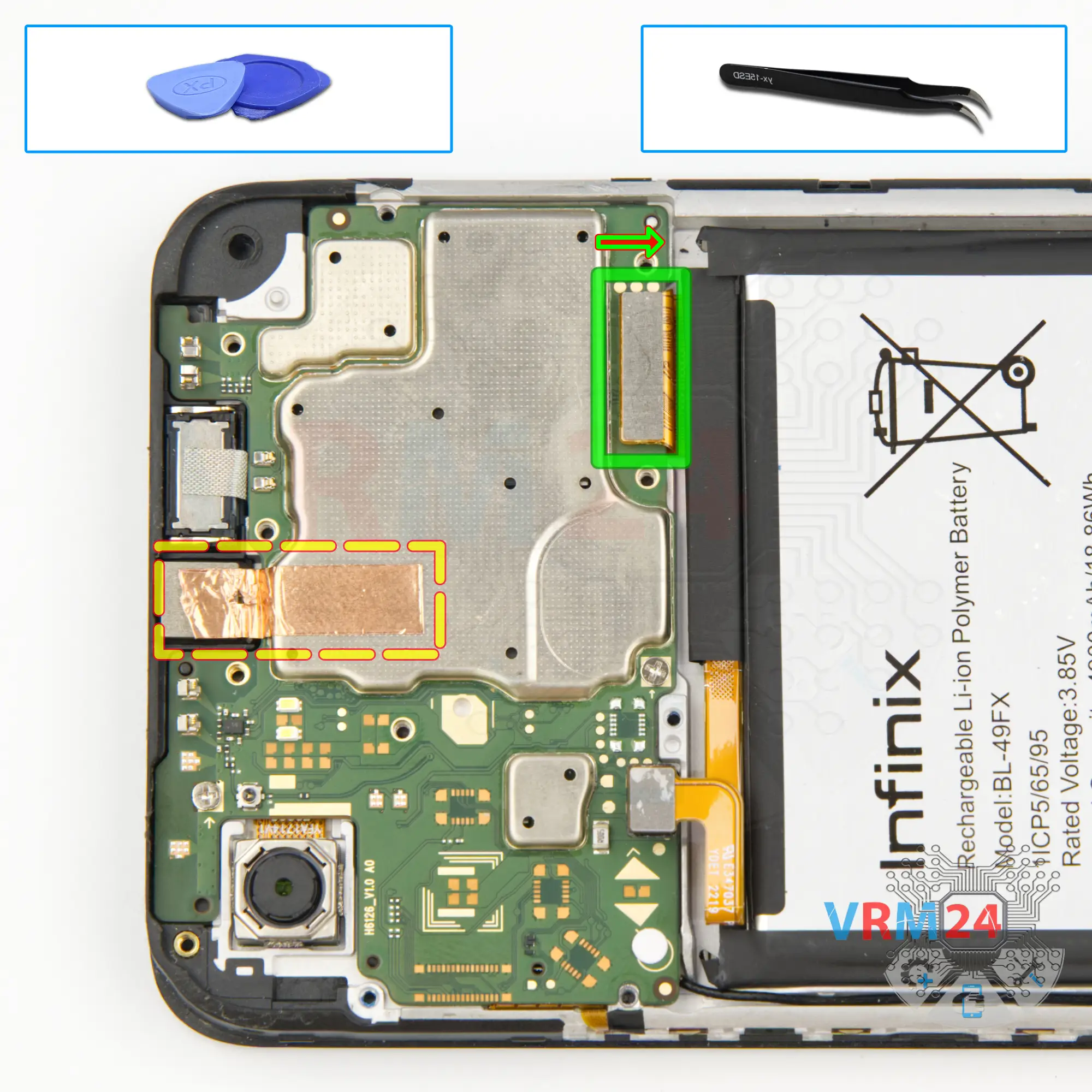
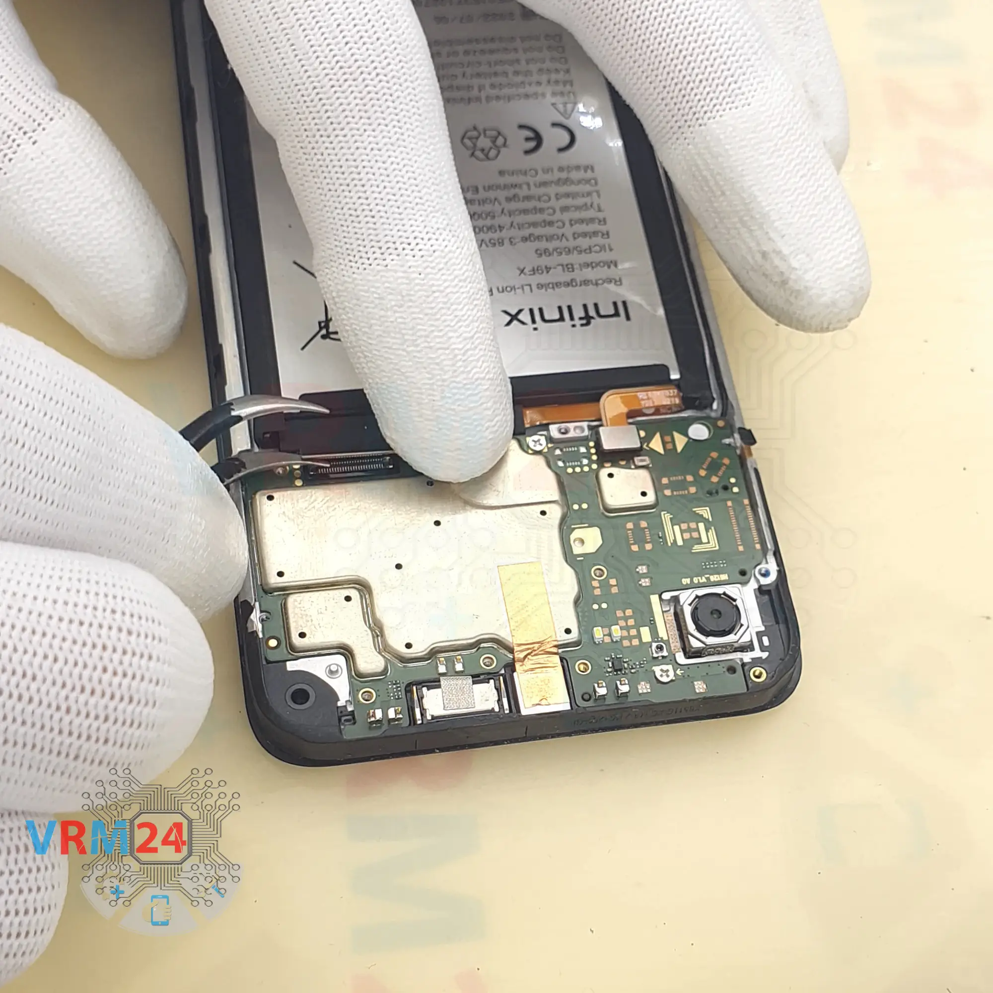
Step 12. Disconnect the connector
We move on to disconnecting the connector on the motherboard. Disconnect the connector of the inter-board cable.
And we can peel off the copper heat dissipating foil on the front camera.
Carefully peel off the foil - the front camera, we will be able to detach only after we remove the motherboard.
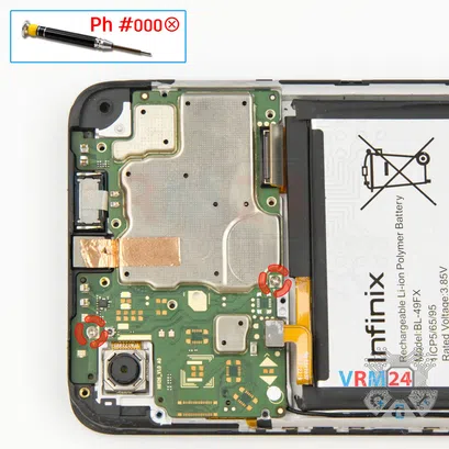


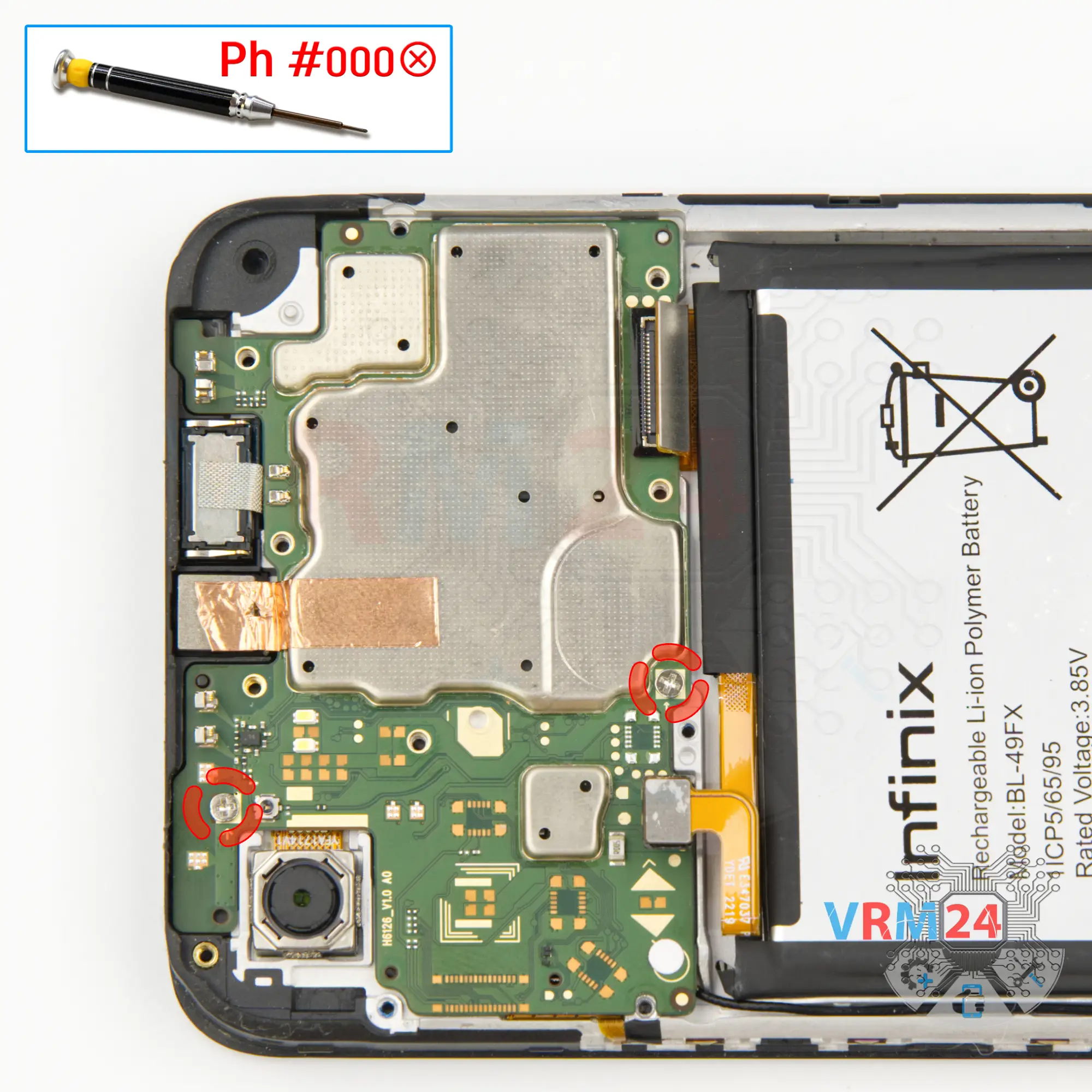
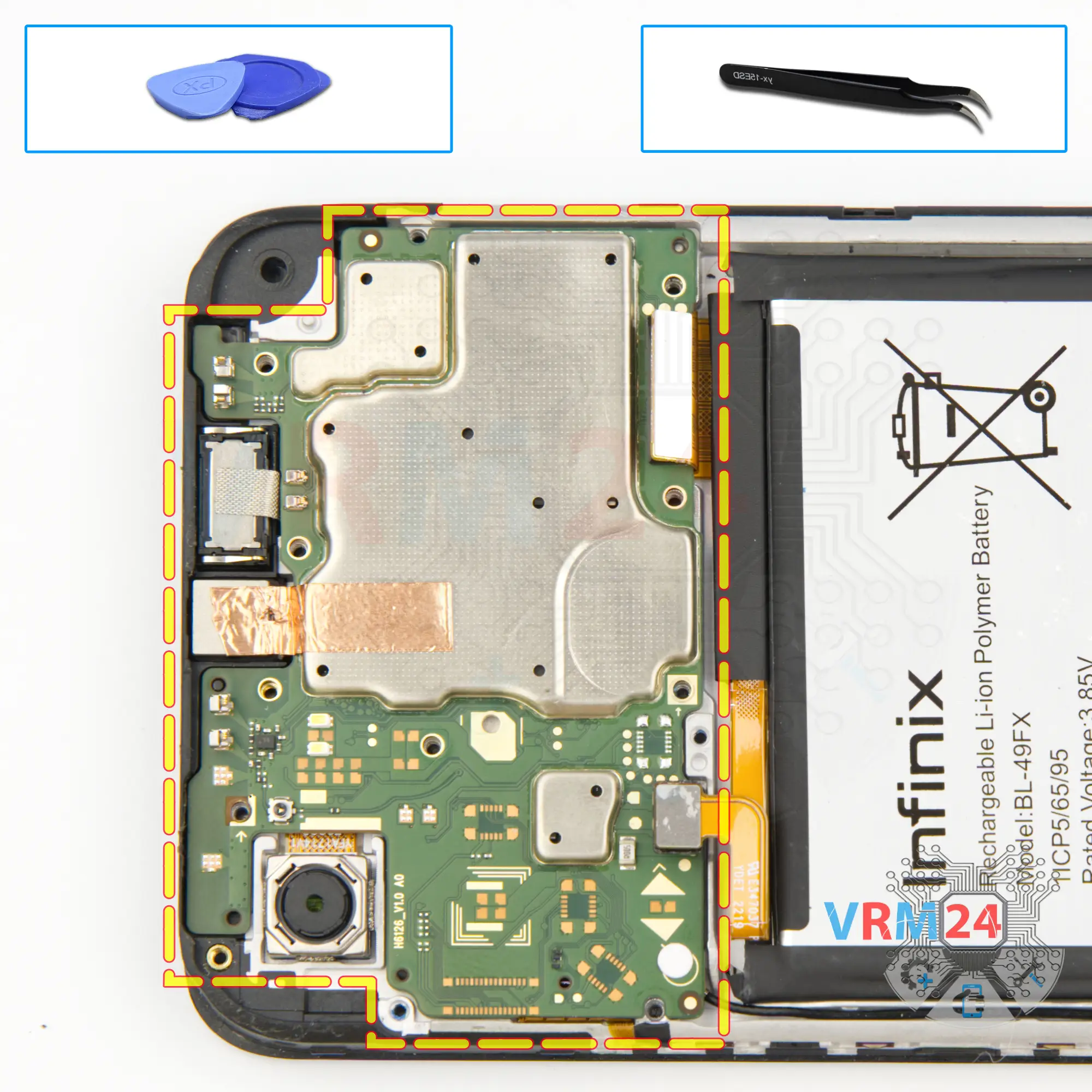
Step 13. Unscrew the screws
Then we need to unscrew the two screws that hold the motherboard. For this we also use a one and a half millimeter Phillips screwdriver or a Philips #000.
It is important to notice where the screws are located so we don't get anything mixed up.
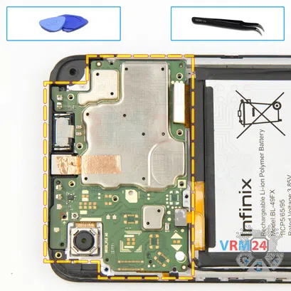

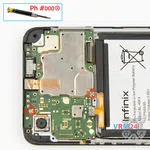
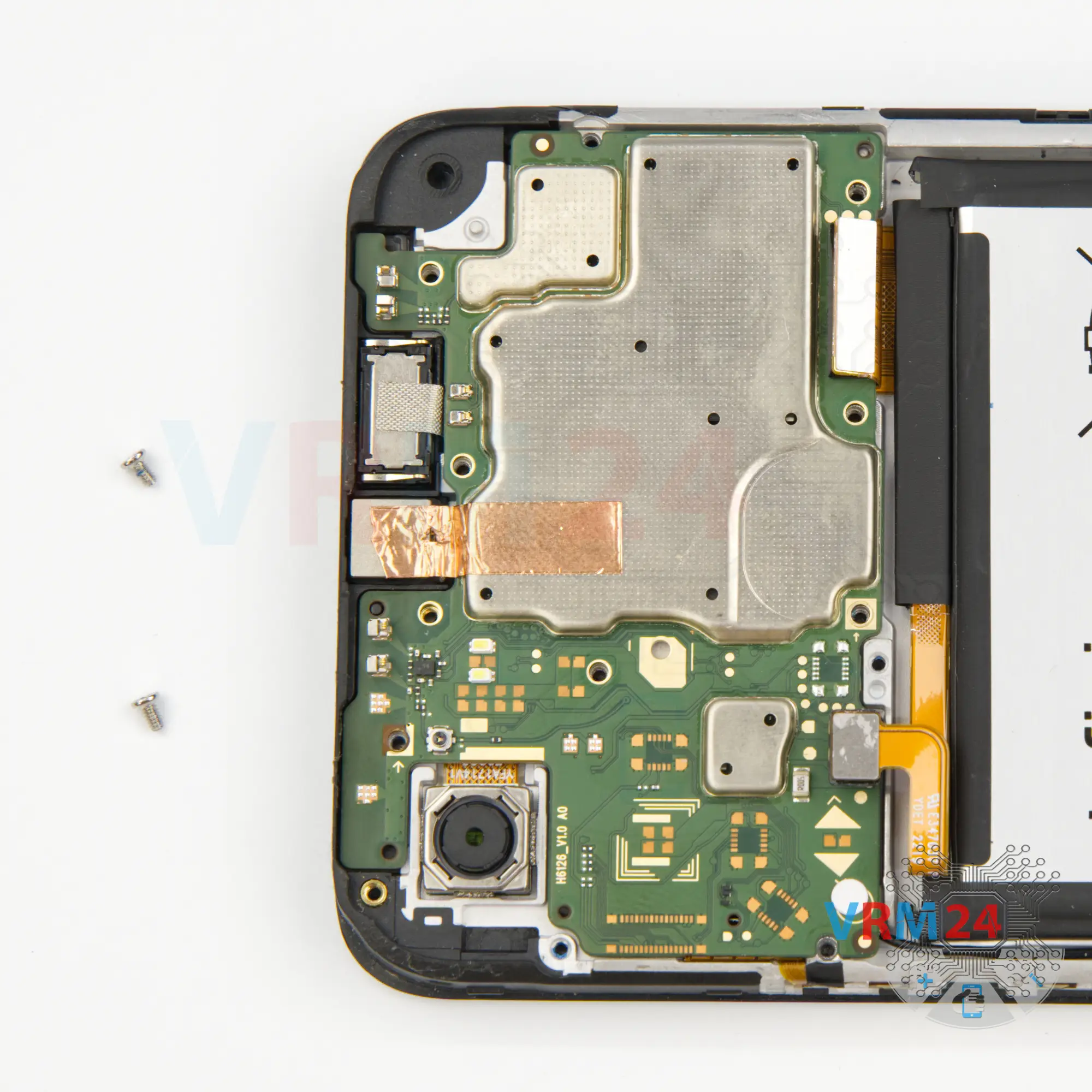
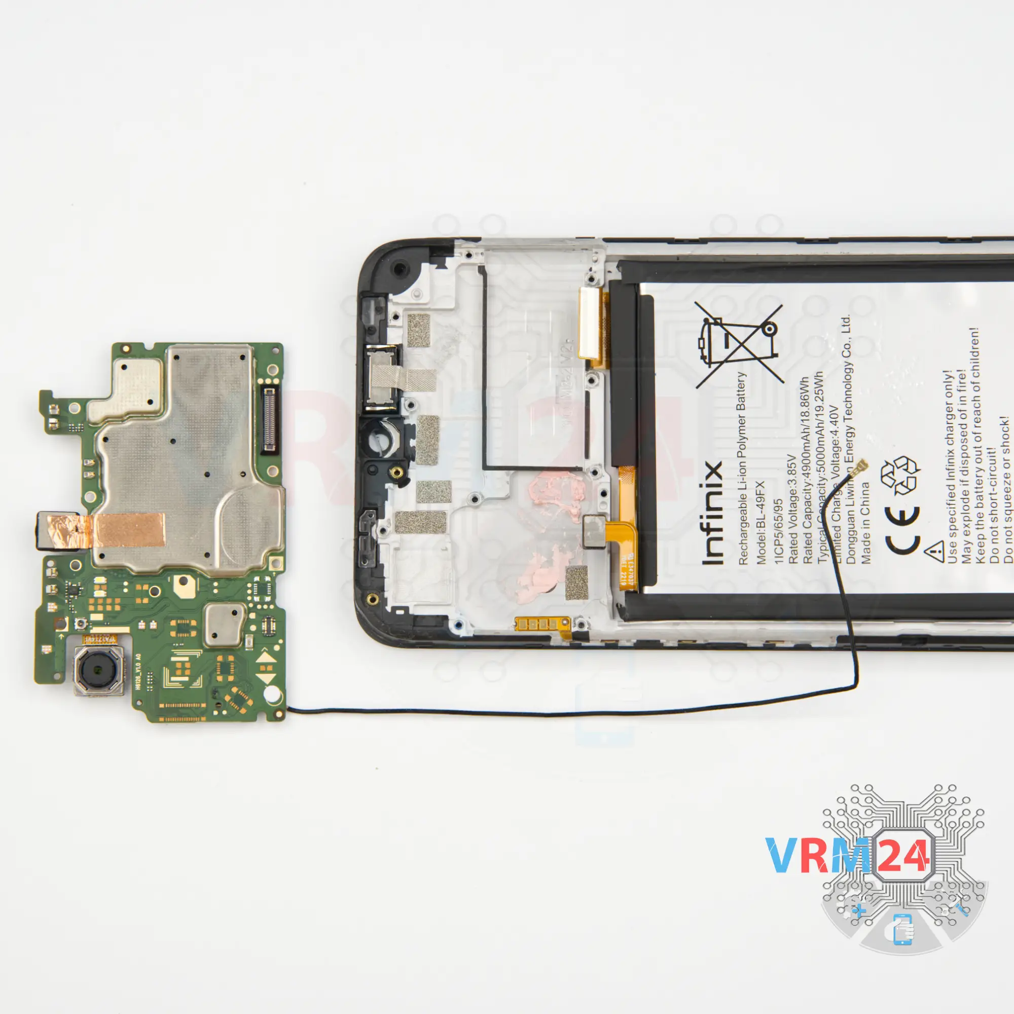
Step 14. Remove the motherboard
And we can detach the motherboard. As always, we need to find the right place where we can pry, gently lift and remove the motherboard.
⚠️️ Do not bend the circuit board when removing it or push tools under it. Unbeknownst to yourself, you can damage components or cables from the inside.
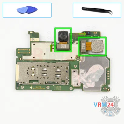
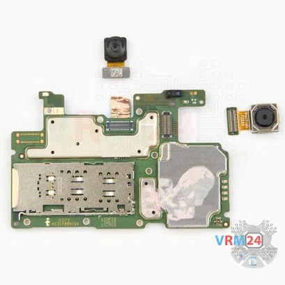

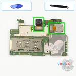
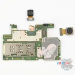
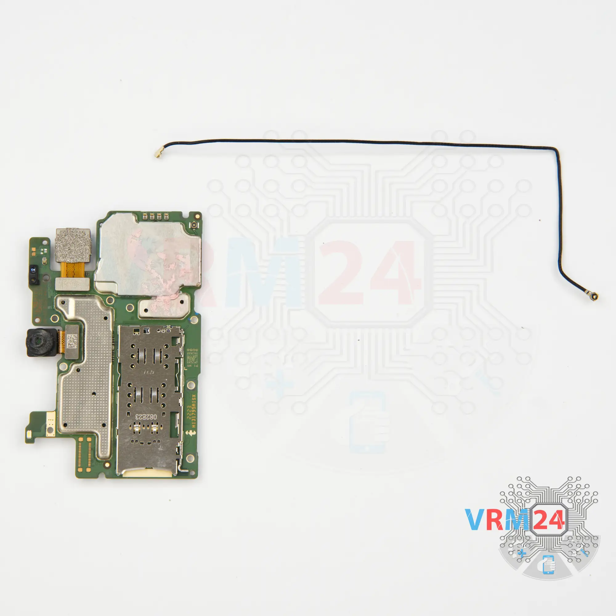
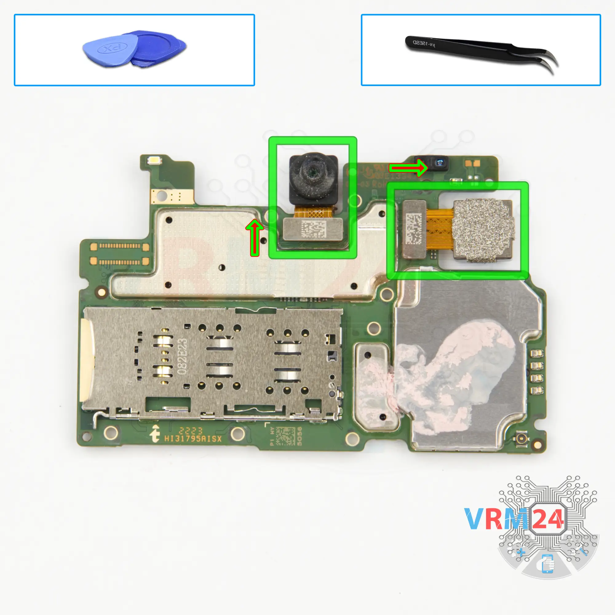
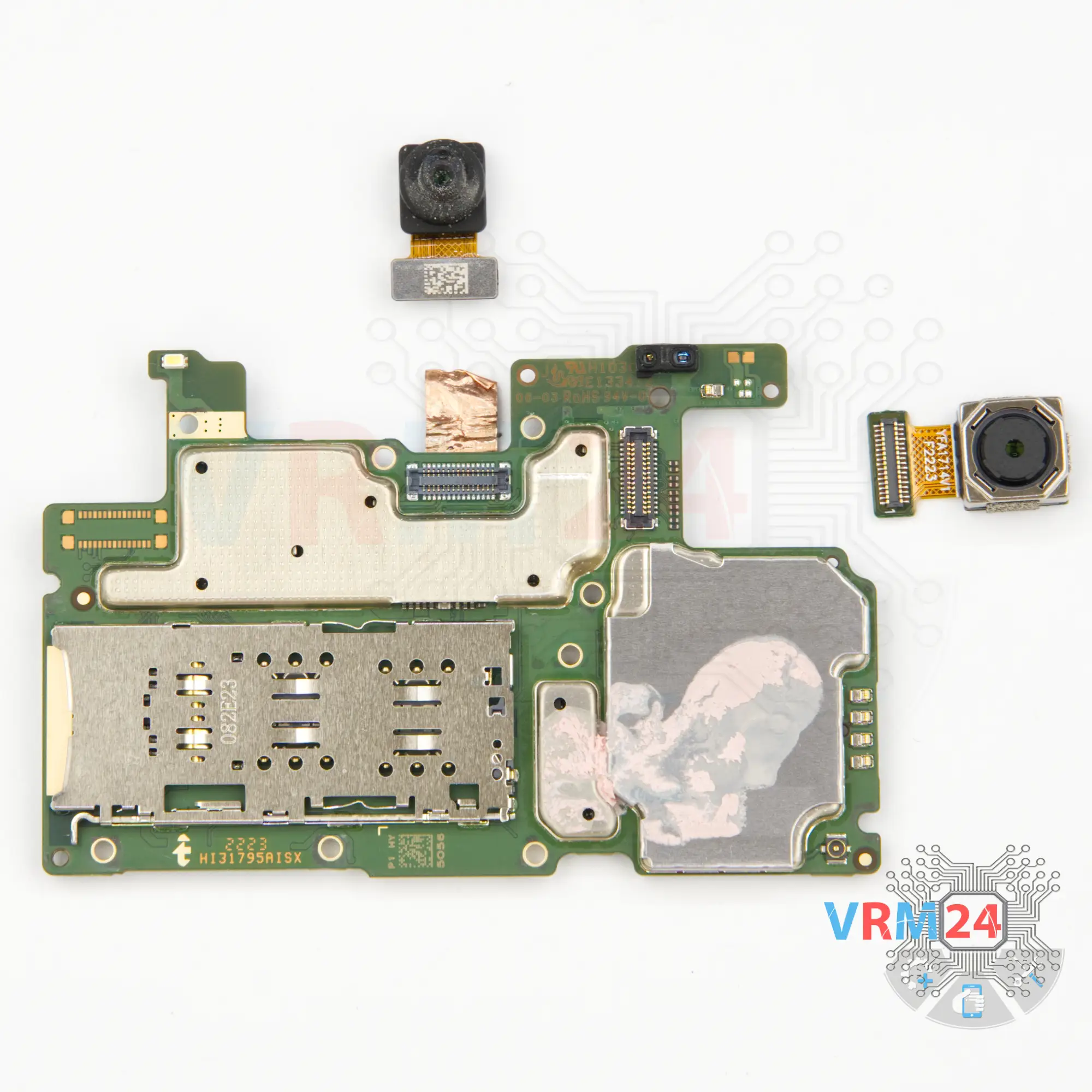
Step 16. Remove the cameras
Then on the motherboard we need to detach the front camera, and we need to detach the main camera.
Carefully hold the cameras so they don't accidentally fall out, detach them and put them aside.
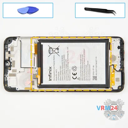


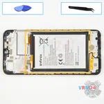


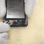
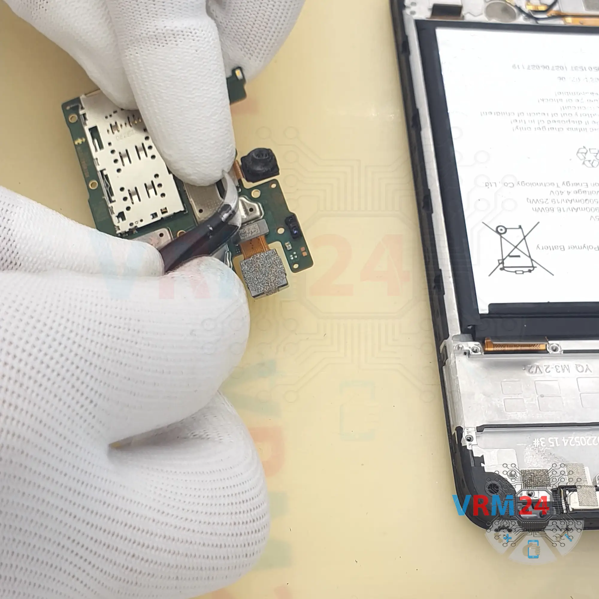
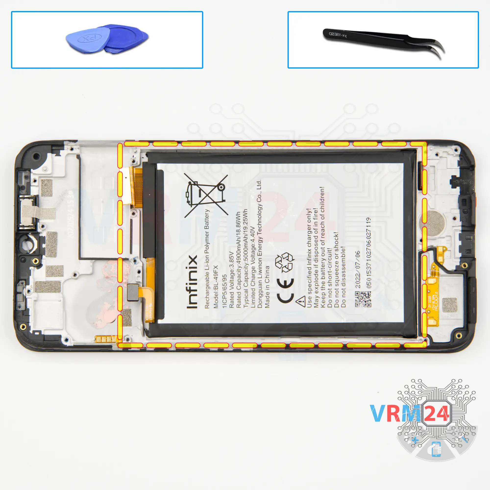
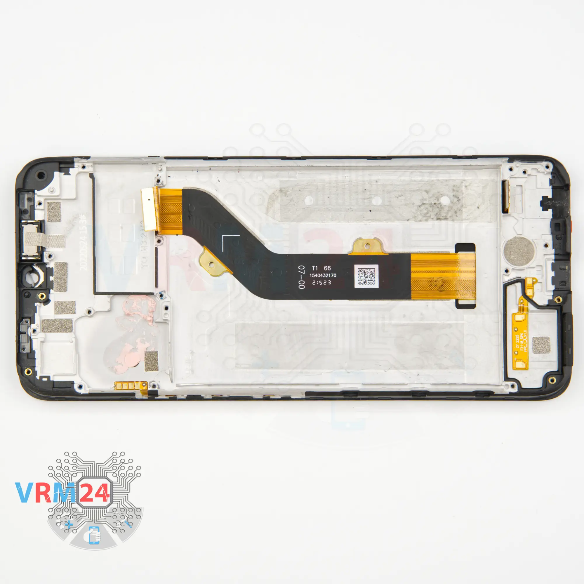
Step 17. Remove the battery
And we move on to detaching the battery.
First, we use a thin plastic film, put it in the gap between the display frame and the battery and gently run it along cutting off the adhesive base.
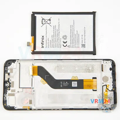
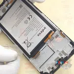
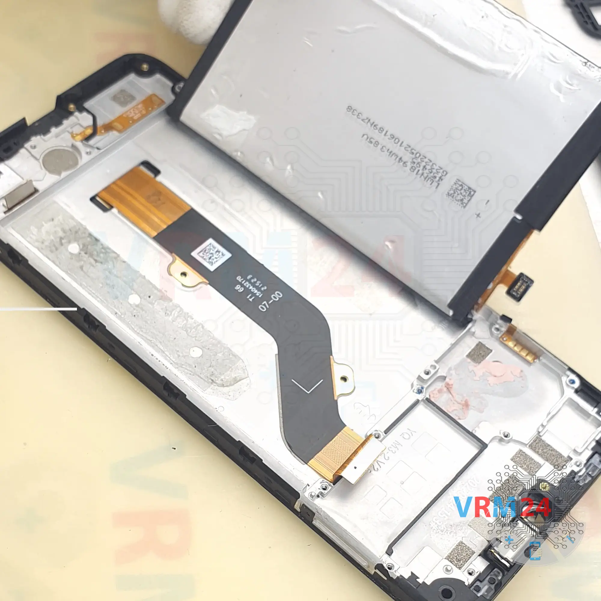
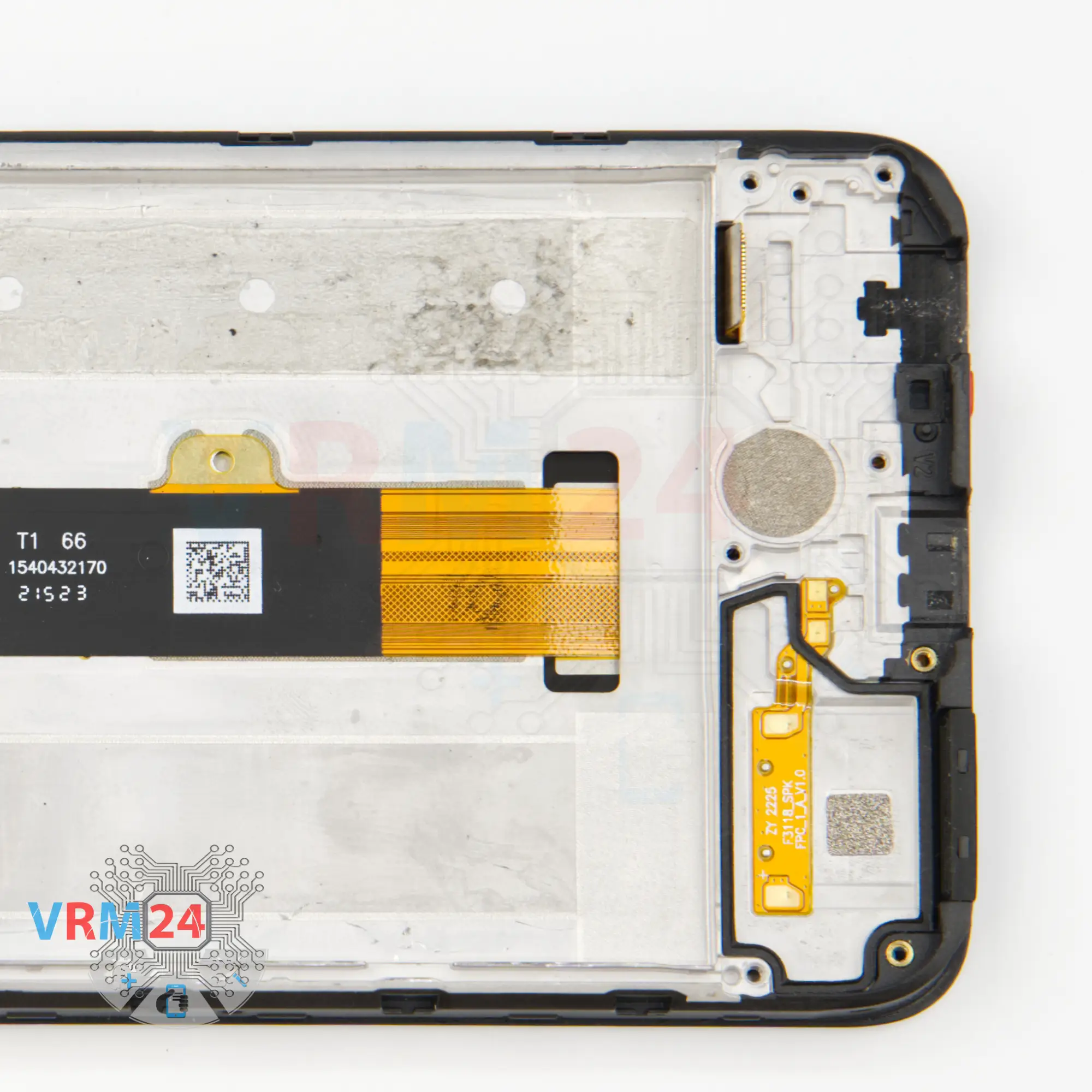
⚠️️ We need to be careful, because we see under the battery, on the side from which we detach the battery, there is an inter-board cable.
We don't know where exactly it is located under the battery. Of course, it is better to rewind our video to the end, to see exactly where the cable is located and only then to work with the tool.
We need to be really careful not to damage the battery shell.
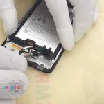
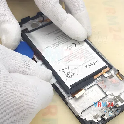
And once we have a good-sized space, we can use a thicker tool, a plastic card.
⚠️️ No need to rush, no need to force, it is really important not to damage anything.
Using the plastic card, we carefully cut off the remaining glue and try to lift and remove the battery.


Detailed disassembly instructions of Infinix Smart 6 HD in the video, made by our mobile repair & service center:
If you have a question, ask us, and we will try to answer in as much detail as possible. If this article was helpful for you, please rate it.

Disassembling\Repair has easy complexity and takes about minutes in time.
Our manual is suitable for all models Infinix Smart 6 HD released for markets in different countries.
Back to the list