




Recommended tools
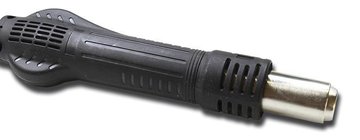
Heat gun
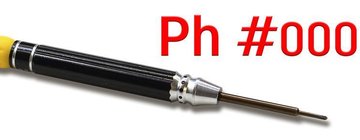
Screwdriver Phillips #000
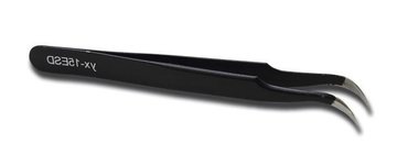
Tweezers
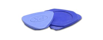
Non-metallic tool
Disassembly/Repair of the mobile device Infinix Zero X Pro with each step description and the required set of tools.
4246
Views
3
Likes
—
Share
0
Questions

Step 1.
Before disassembling!
⚠️ Before disassembling, do not forget to turn your phone off.
Step 2.
Remove the tray
At the very beginning we need to remove the card tray.
For this we take a special tool, insert it into the hole and push out the card tray.
⚠️ If the tray does not come out well, we can additionally use tweezers.
Step 3.
Open the back cover
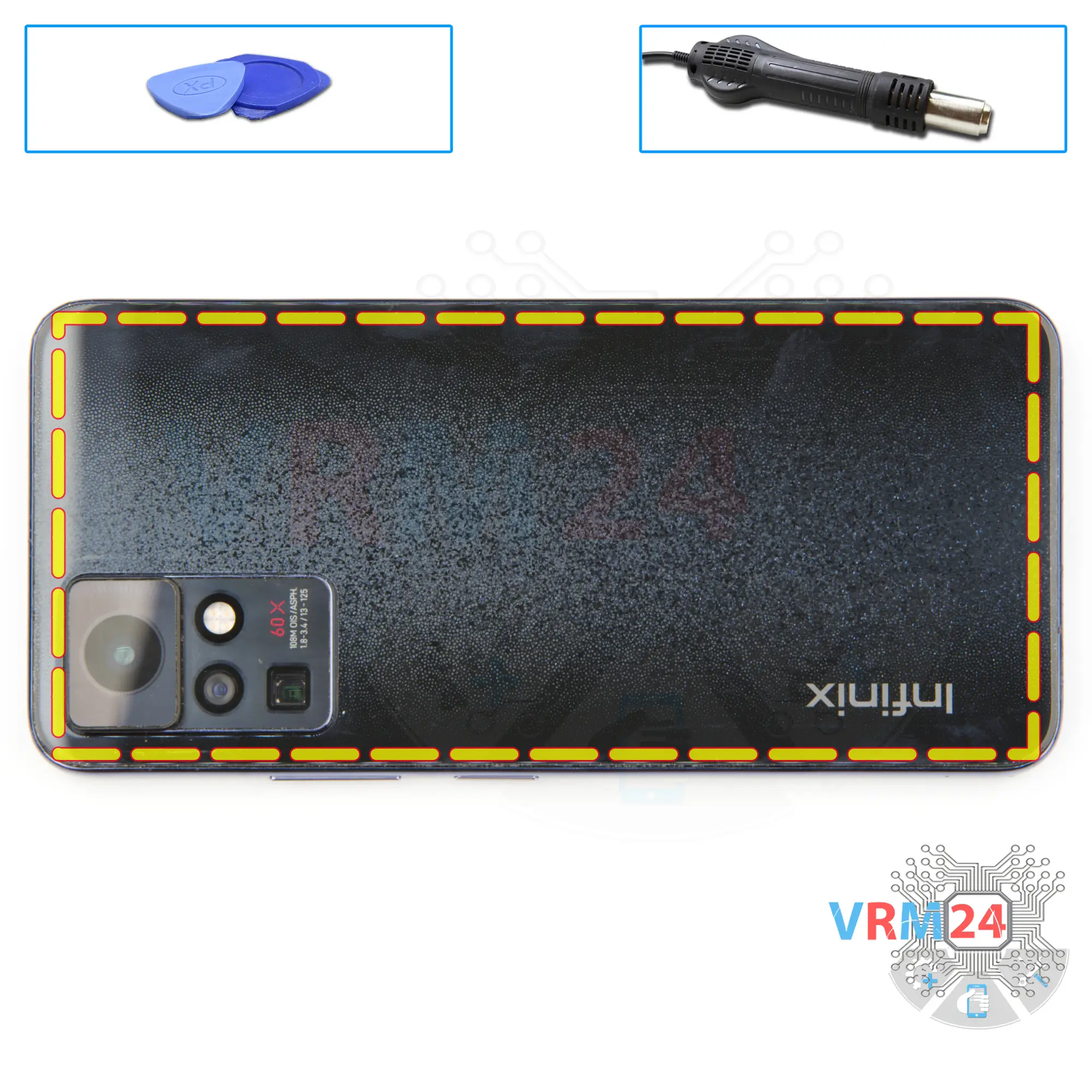
We need to heat the surface of the back cover to a temperature of about 70° C or 160° F. For this we use a heating mat you can use a hair dryer.
And after 5 to 7 minutes we can move on to disassembly.
To detach the back cover, we will use a plastic film, it can be a protective film from a new display or a film from the stationery store. We insert the film into the gap between the middle cover and the back cover and run it lengthwise cutting off the adhesive base.
Step 4.
Unscrew the screws
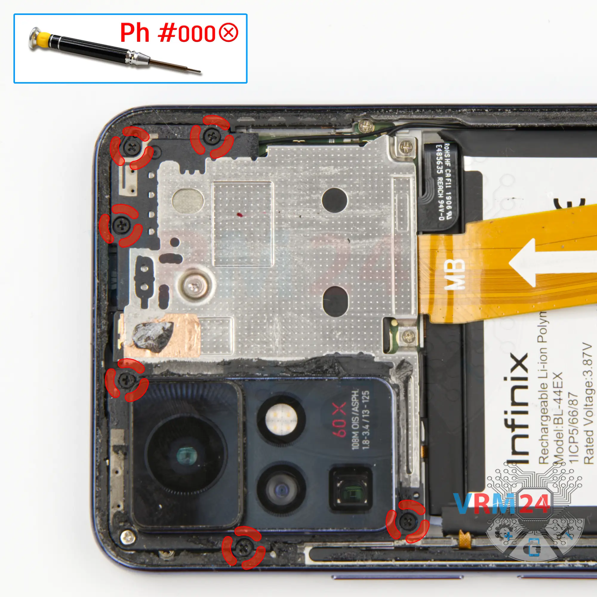
Using a screwdriver Phillips 1.5 mm (PH #000), unscrew the six black screws.
Step 5.
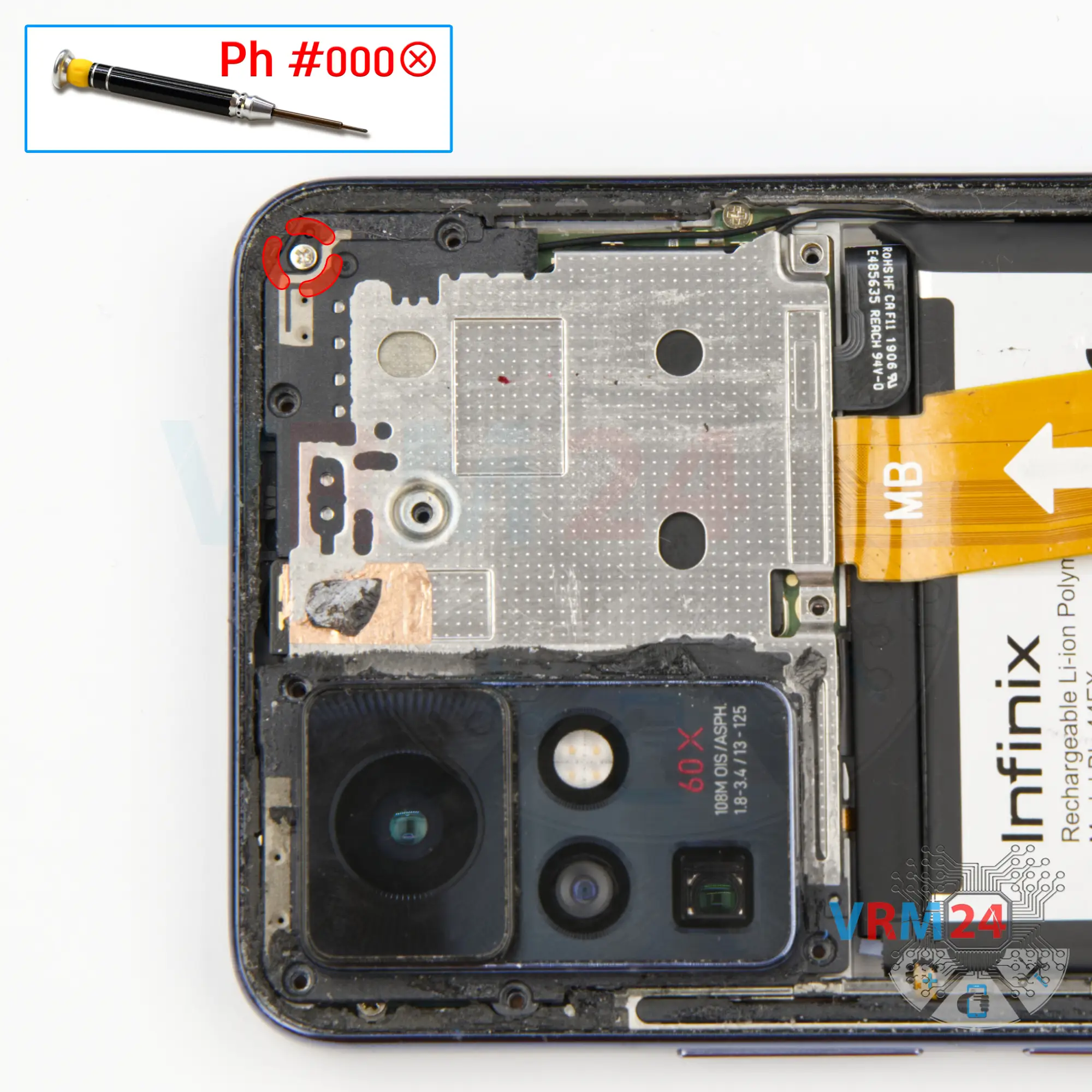
Unscrew one screw
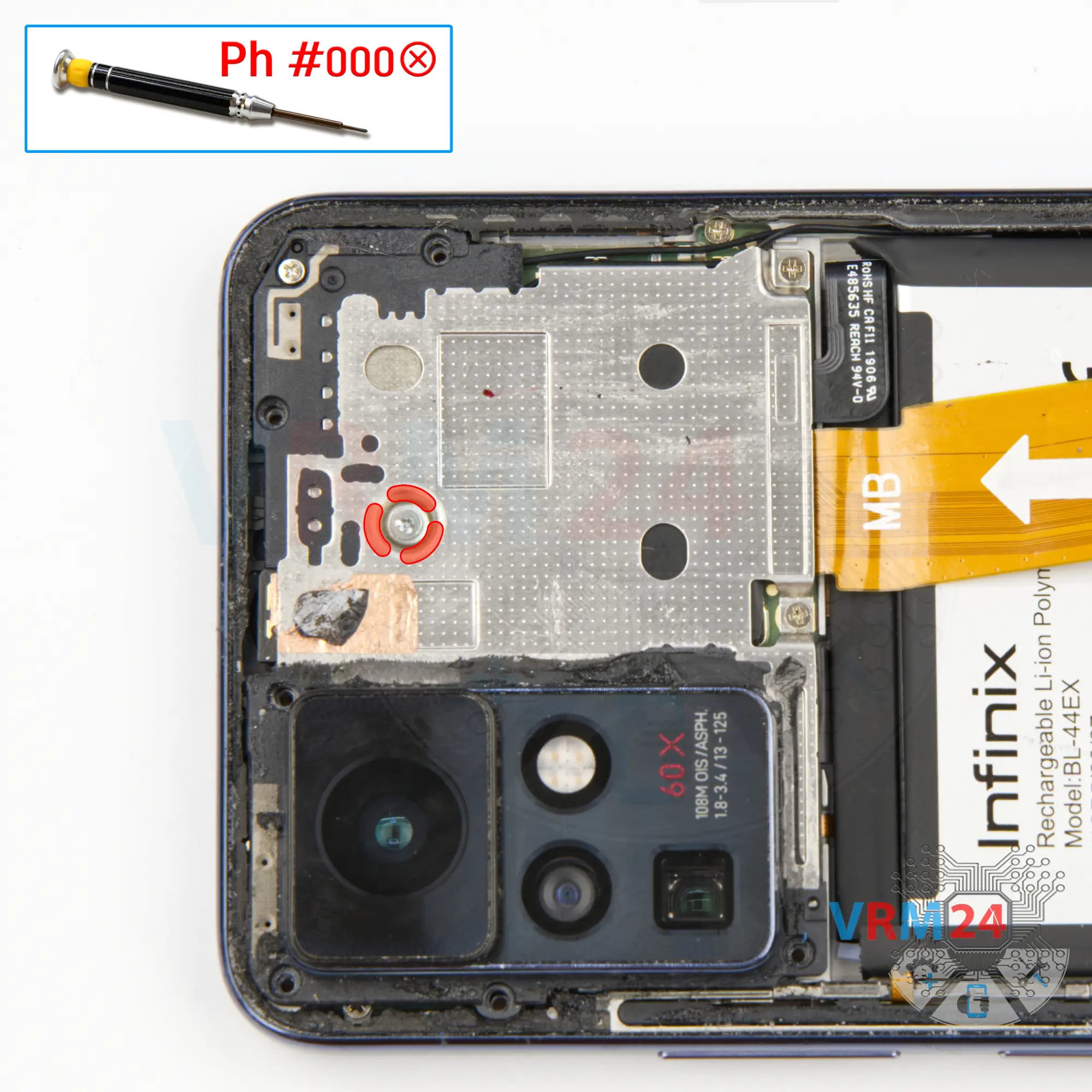
Using a screwdriver Phillips 1.5 mm (PH #000), unscrew the one large silver screw.
If the screws are different:
ℹ️ Be sure to note the location of the screws before disassembling. When assembling the device, screwing the screw in the wrong place may damage the device or its parts. To avoid damage, the removed screws and individual pieces (as gaskets or brackets) must be laid out in the appropriate order, or the screws and their holes in the phone must be marked with colored markers.
Step 6.
Unscrew the screws
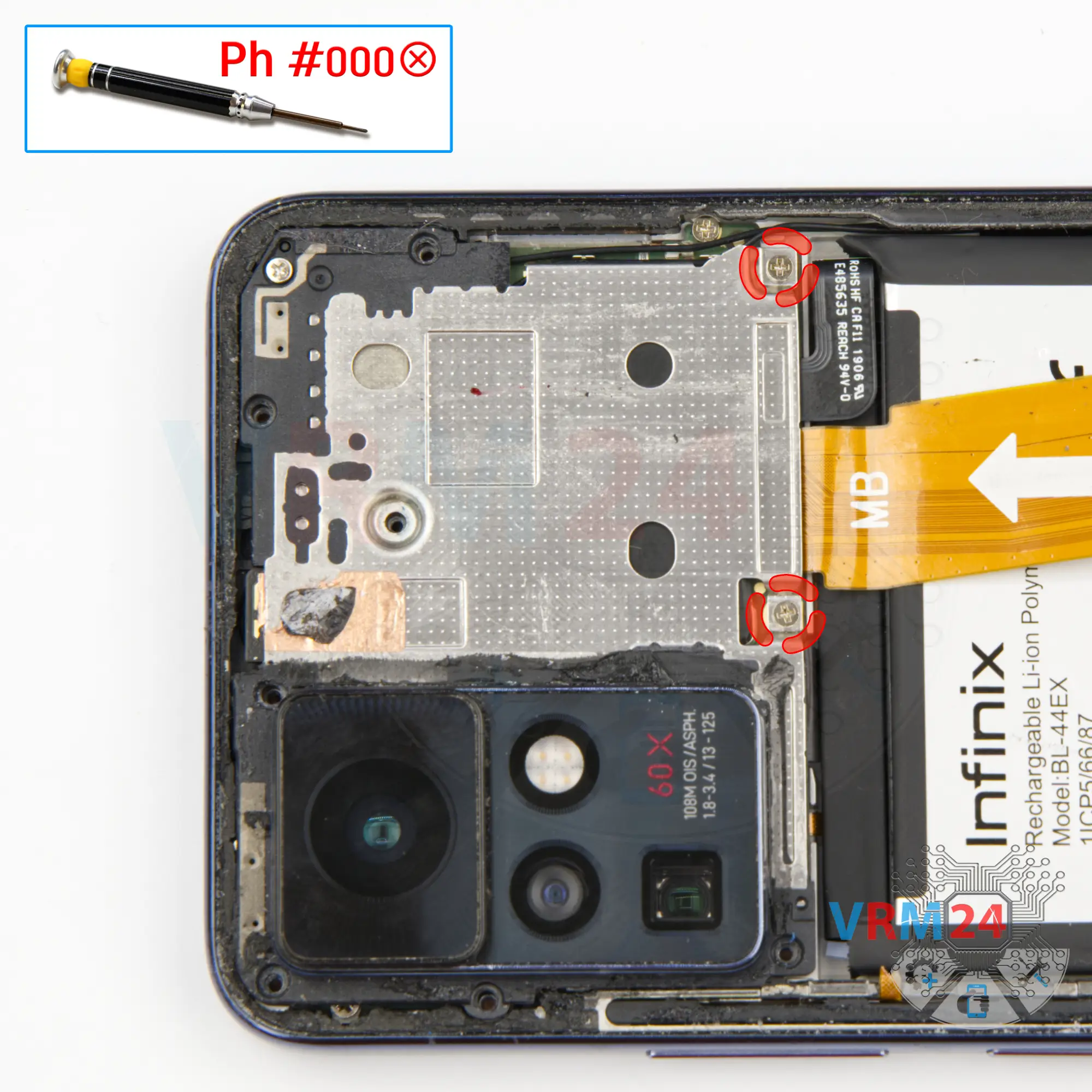
Using a screwdriver Phillips 1.5 mm (PH #000), unscrew the two silver screws.
Step 7.
Unscrew one screw
Using a screwdriver Phillips 1.5 mm (PH #000), unscrew the one silver screw.
Please note that the screws are different from each other, in size, color and shape, so we recommend that you place them on a special surface in an easy-to-remember order, so that you do not confuse anything when reassembling. You can also take a picture of the screws before unscrewing them.
Step 8.
Open the cover
And we can detach the cover hiding the motherboard. Gently we pry up the edge in the right place and lift the cover.
It's strange, of course, but we have the cover detached with a large rear camera.
Step 9.
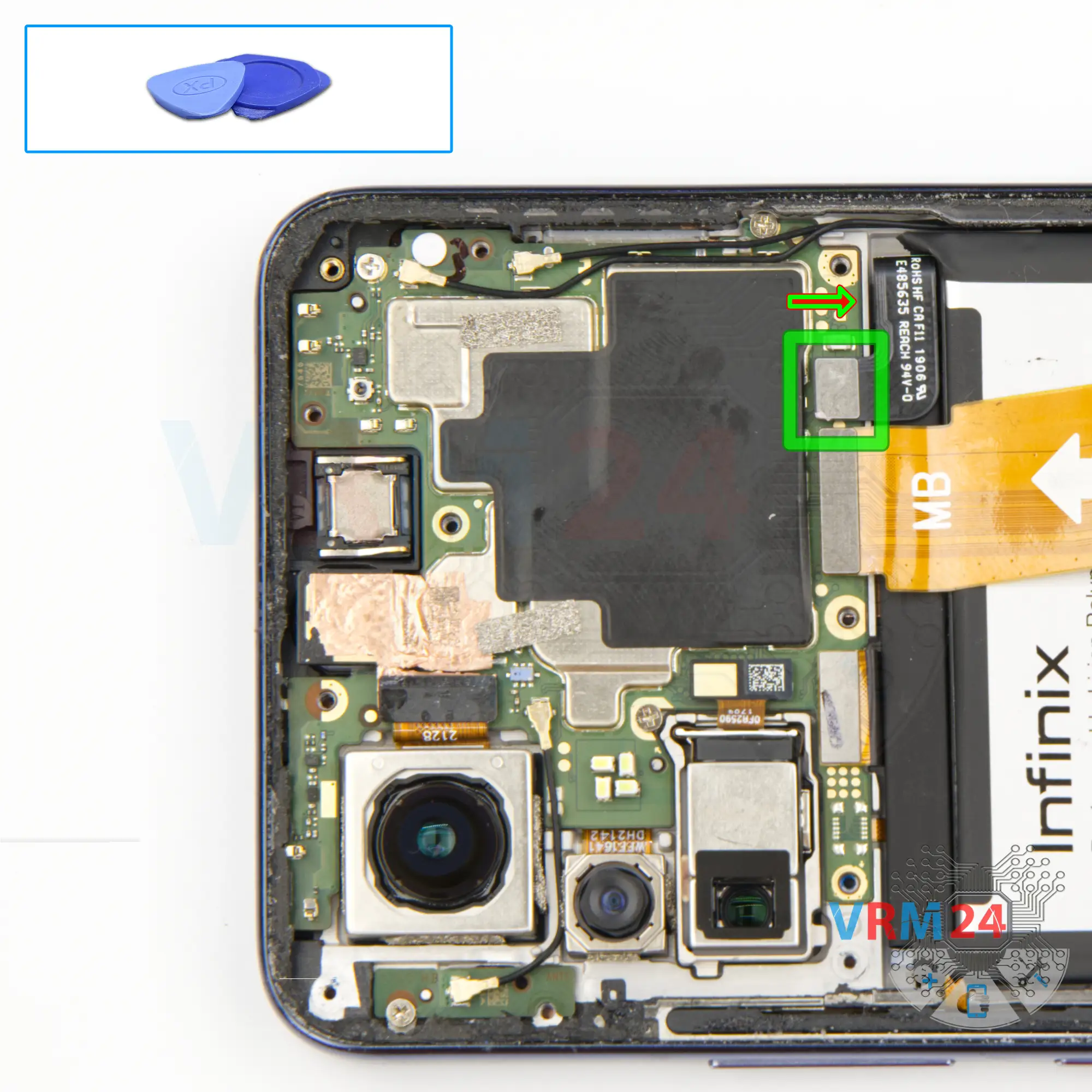
Disconnect the battery connector
Disconnect the battery connector as soon as you can. Use a non-metallic or plastic tool to avoid any damage.
ℹ️ The Infinix Zero X Pro model has a battery BL-44EX with a capacity of 4500 mAh (also known as a rechargeable battery).
Step 10.
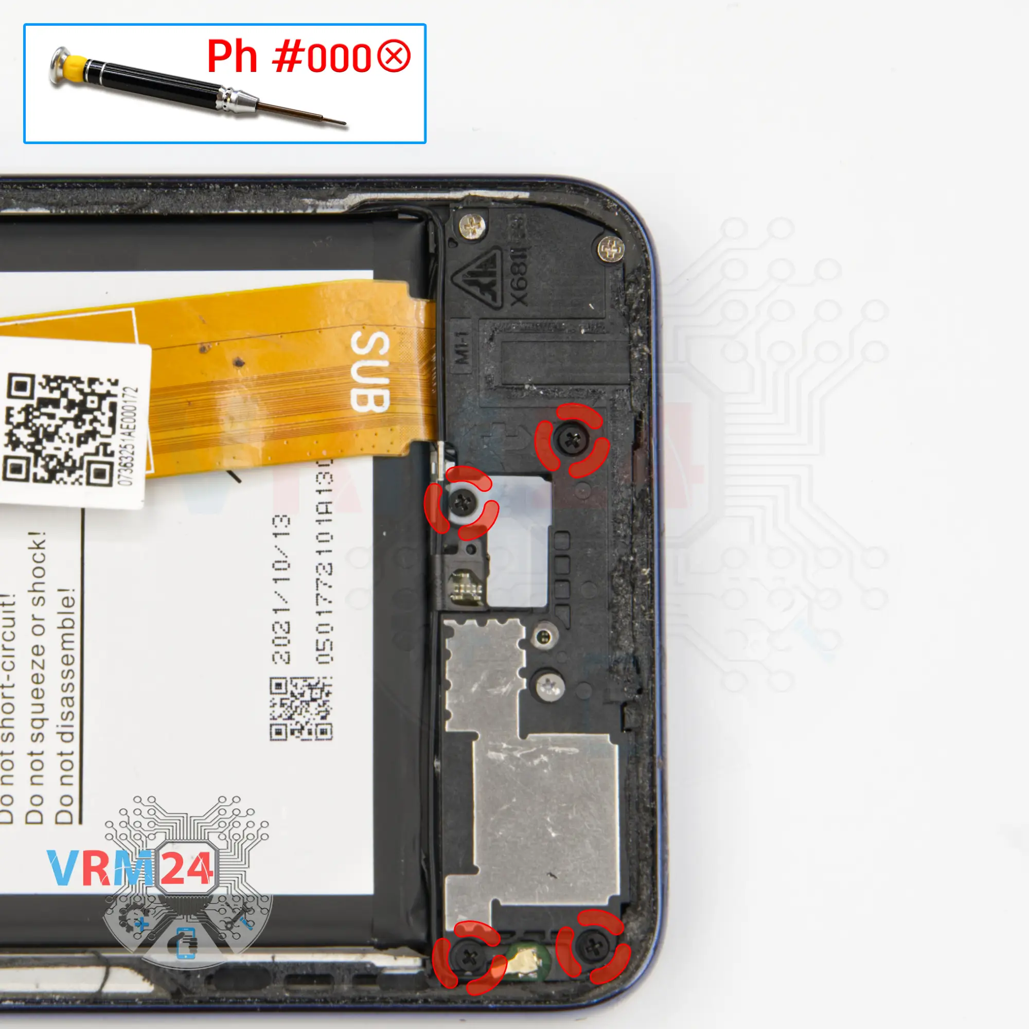
Unscrew the screws
And we move on to unscrewing the four black screws at the bottom. The screwdriver is the same 1.5 mm Phillips screwdriver.
⚠️ The screws are also different from each other, so we need to remind you again that we recommend that you place the screws on a special surface in an easy to remember order for reassembly and they can also be photographed before unscrewing. And if the screws get stuck, we use tweezers.
Step 11.
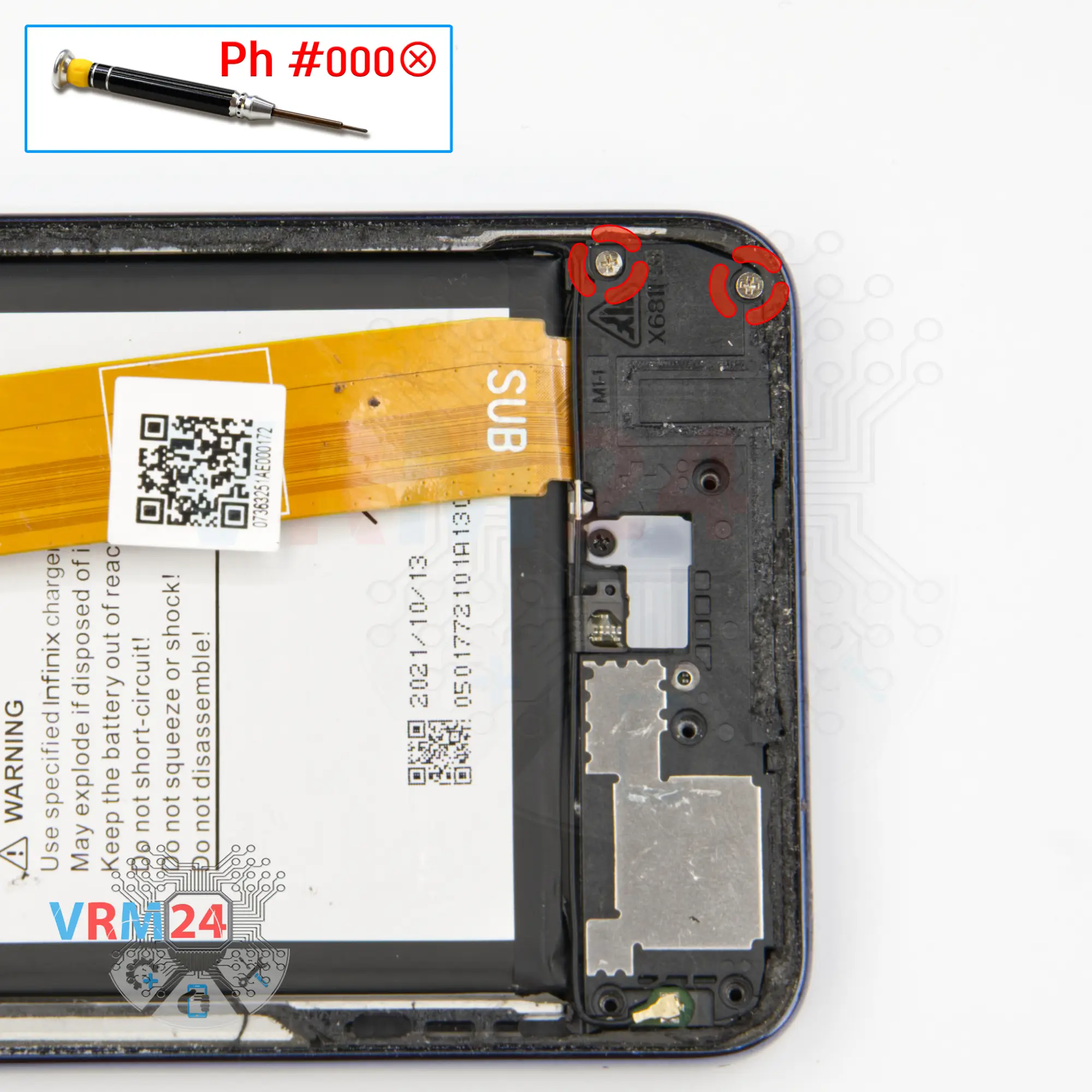
Unscrew the screws
Using a screwdriver Phillips 1.5 mm (PH #000), unscrew the two small silver screws.
Step 12.
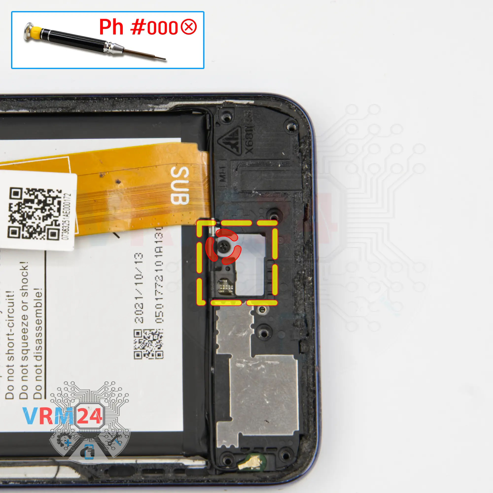
Unscrew one screw
Using a screwdriver Phillips 1.5 mm (PH #000), unscrew one screw, and we remove the small cover hiding the underscreen cable connector.
Step 13.
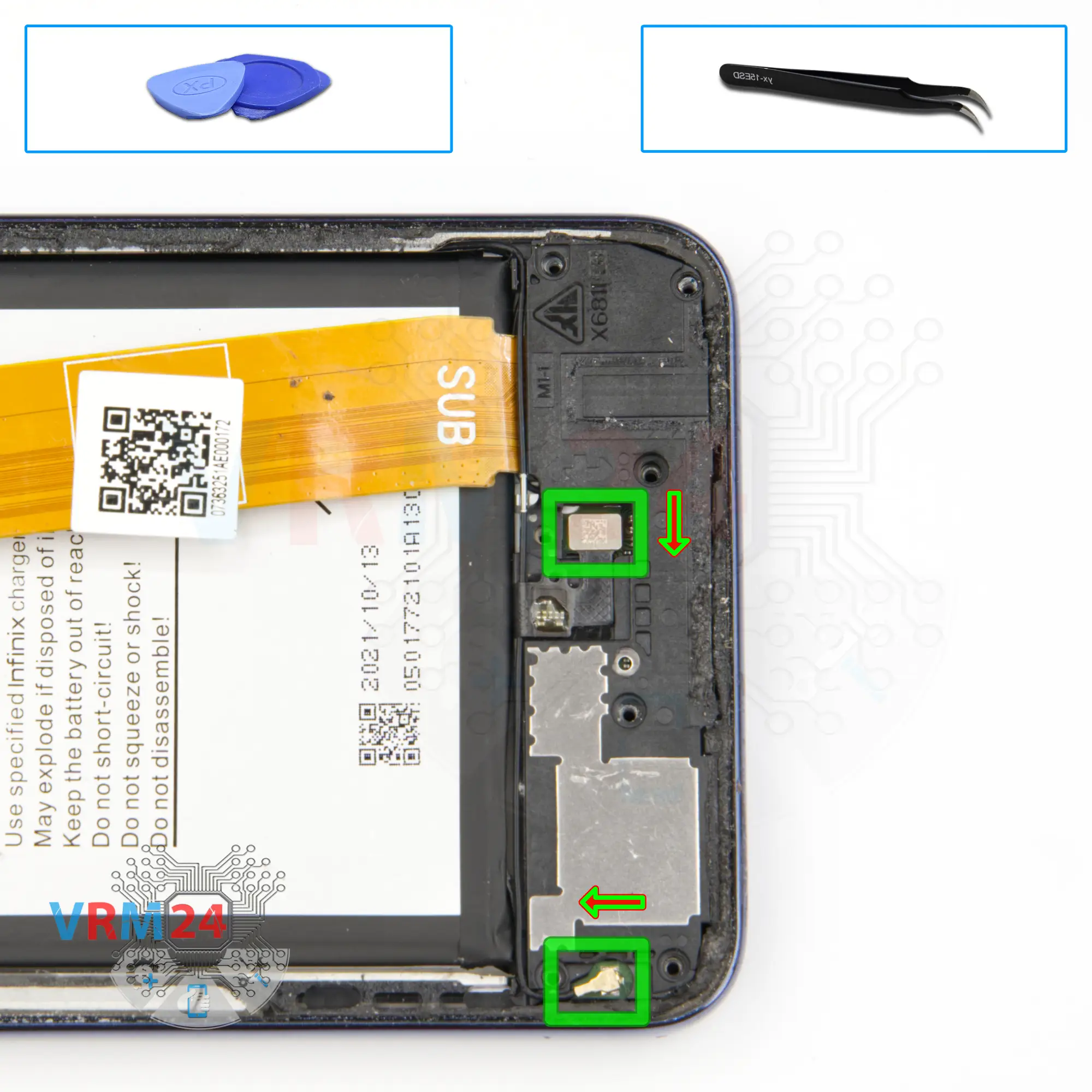
Disconnect the connectors
We disconnect the connector and bend the cable so it doesn't get in the way.
We need to disconnect the coaxial cable connector on the small antenna board and remove a part of the cable from the indentation in the cover.
Step 14.
Remove the loudspeaker
And we can try to detach the cover with a loudspeaker. We find the right and convenient place to hook the cover and try to lift it off.
The cover is glued, on one side, we need to lift it carefully as not to damage anything.
Step 15.
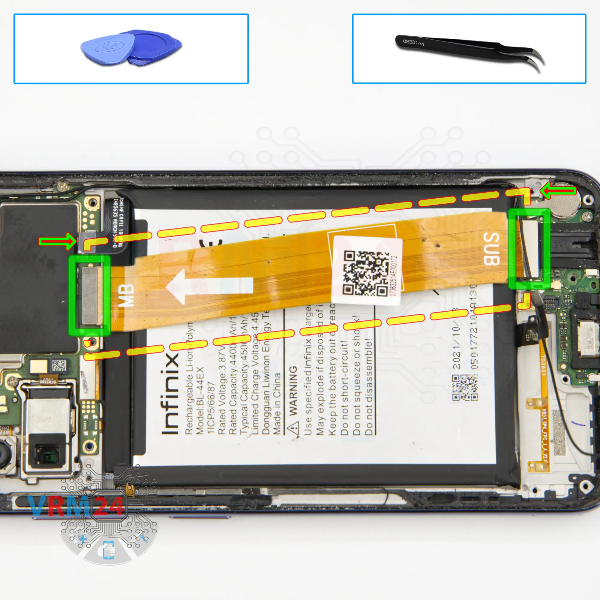
Remove the interconnect cable
Then we disconnect the connectors on the motherboard and sub-board and remove the inter-board cable.
ℹ️ An arrow on the FFC cable (flexible flat cable) indicates its correct position.
Step 16.
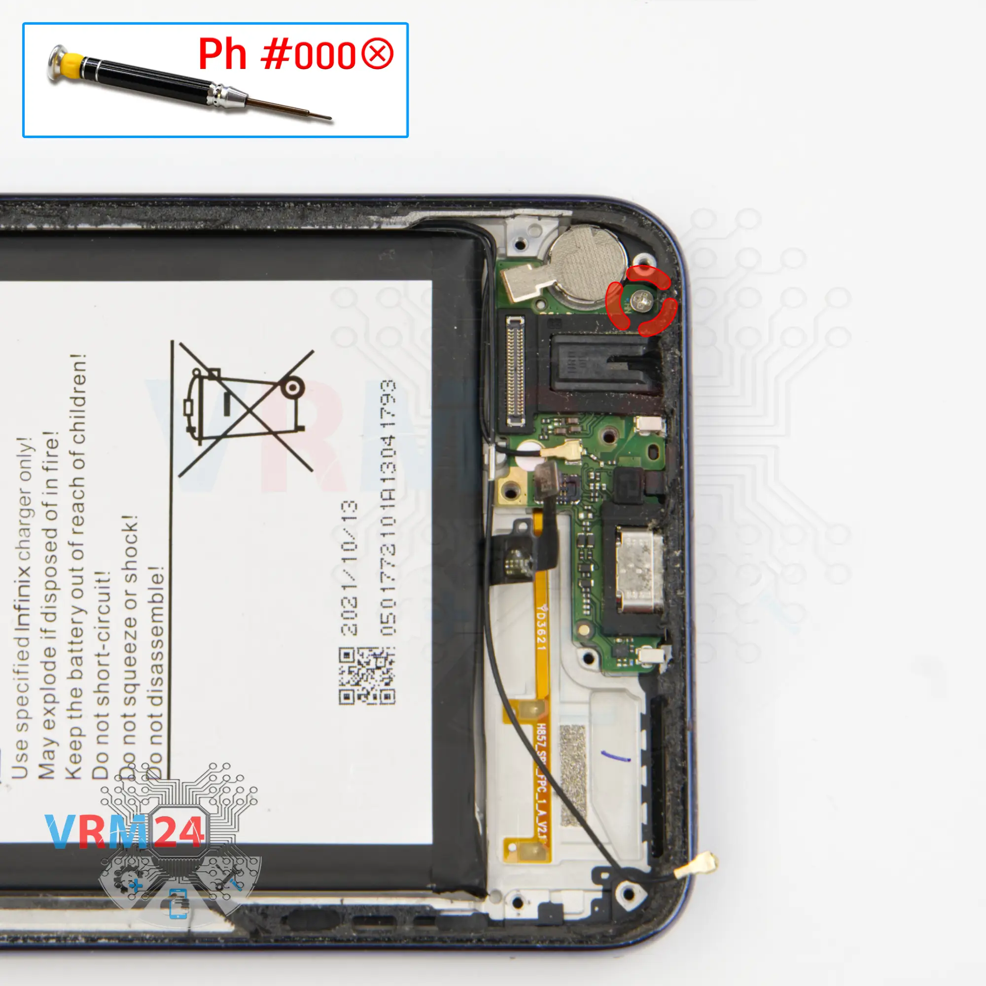
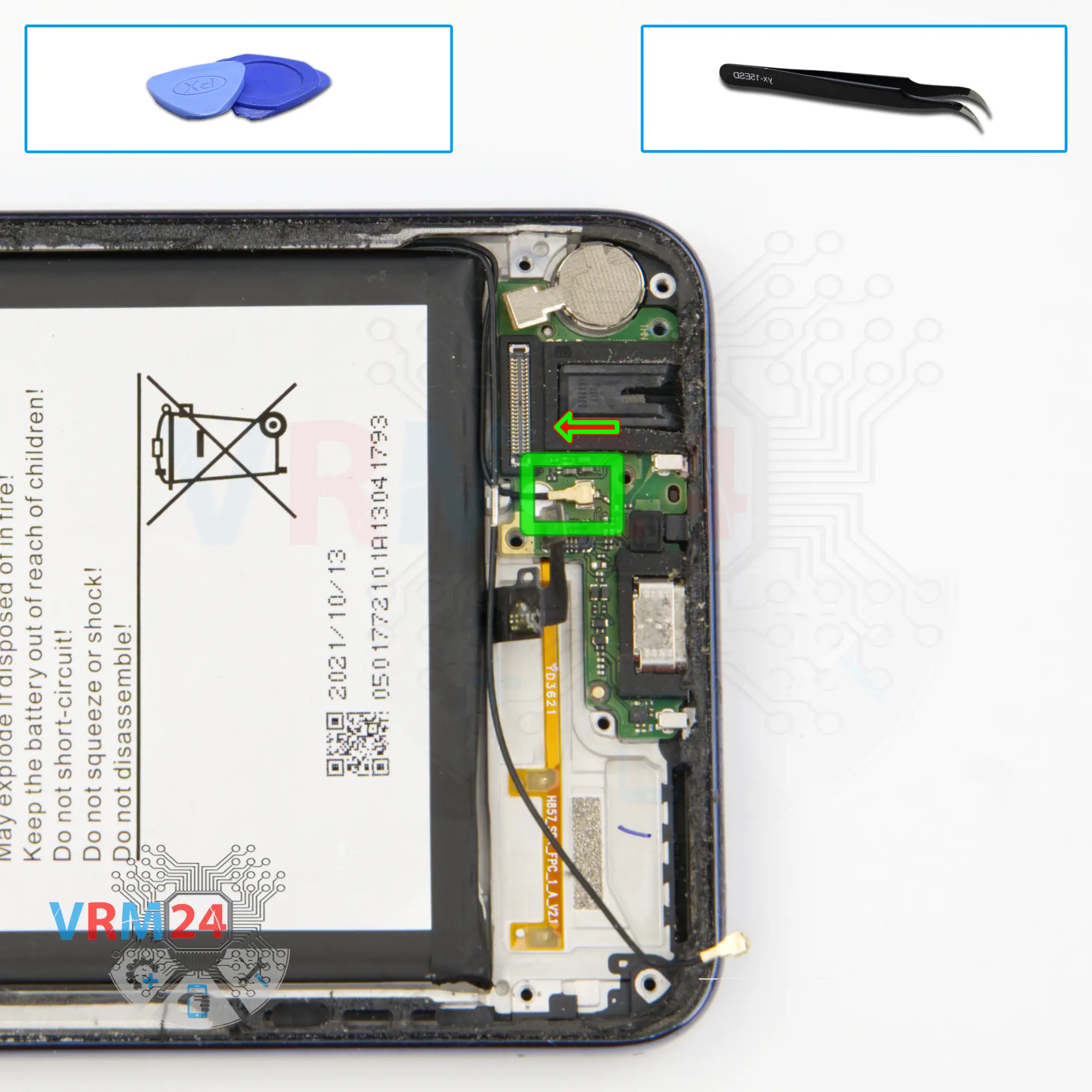
Unscrew one screw
We need to remove one screw securing the sub-board. The screwdriver is the same Phillips 1.5 mm, and this screw is also different from the previous ones.
Step 17.
Disconnect the connector
After that we disconnect the coaxial cable connector.
Step 18.
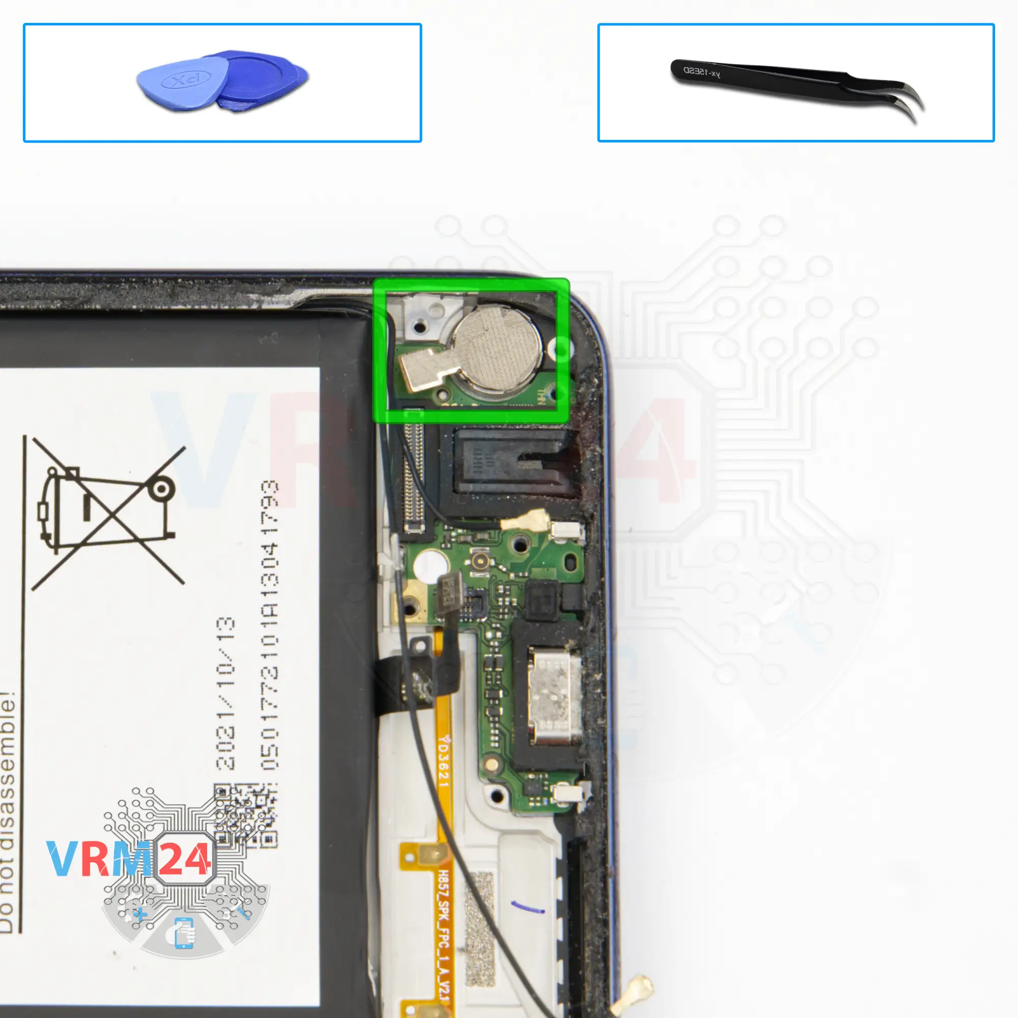
Remove the vibration motor
To remove the sub-board, we need to first detach the vibration motor. Since the contact area of the vibration motor on this model comes from the top, unlike all the others.
We hook the vibration motor to the base and carefully unglue it.
Step 19.
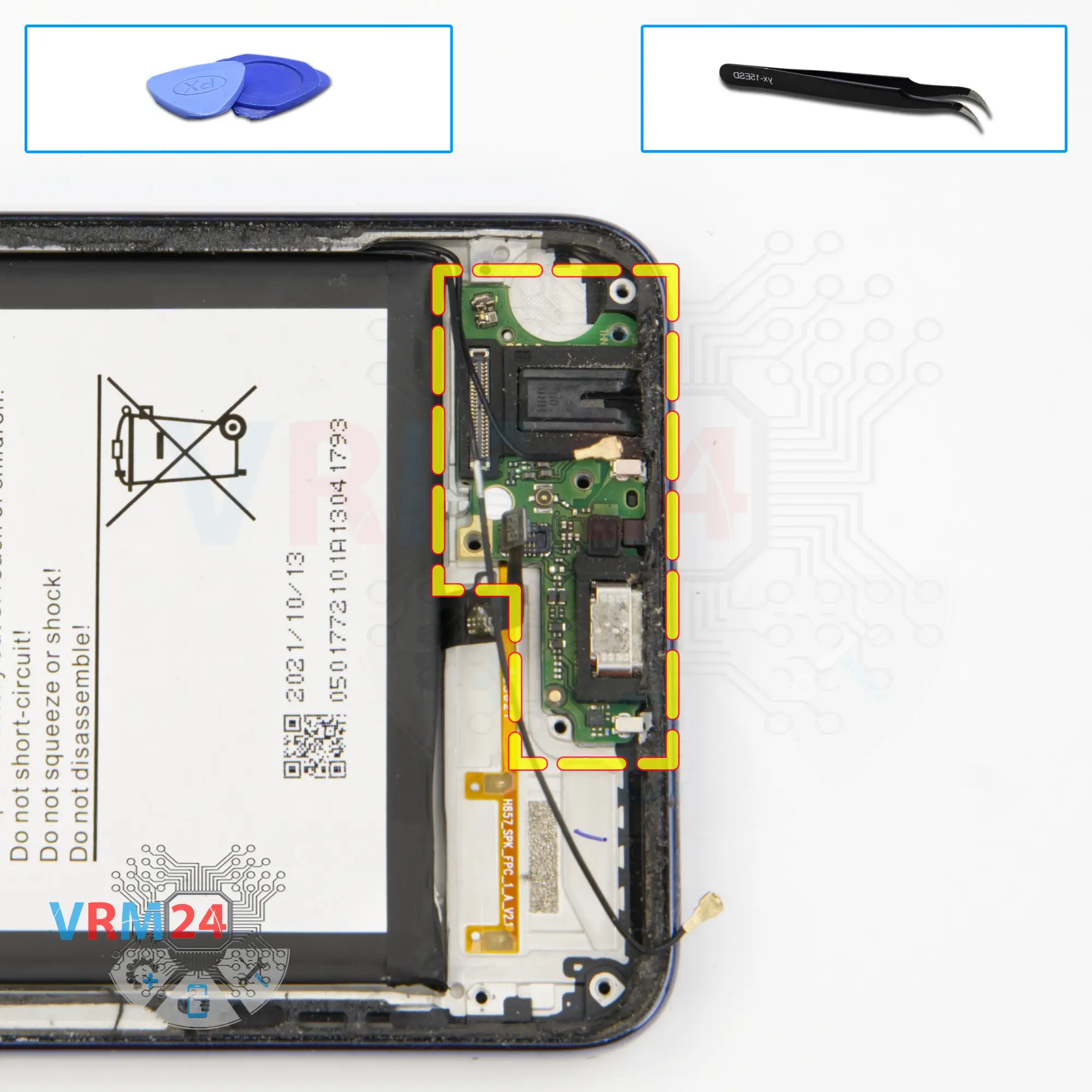
Remove the sub-board
And we can easily remove the sub-board.
On the sub-board we have a charging port, microphone and headset jack ports.
Step 20.
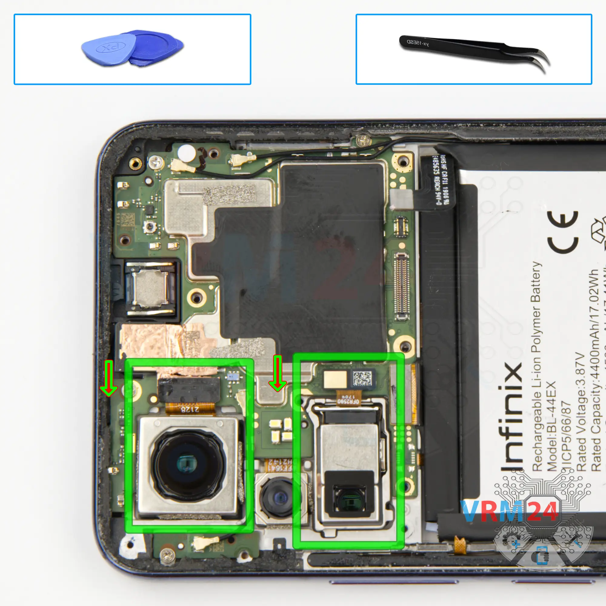
Remove the cameras
We can also peel off the copper heat dissipating coating on the front camera. We will remove the camera later.
After, we detach the two rear cameras and put them aside.
Step 21.
Disconnect the connectors
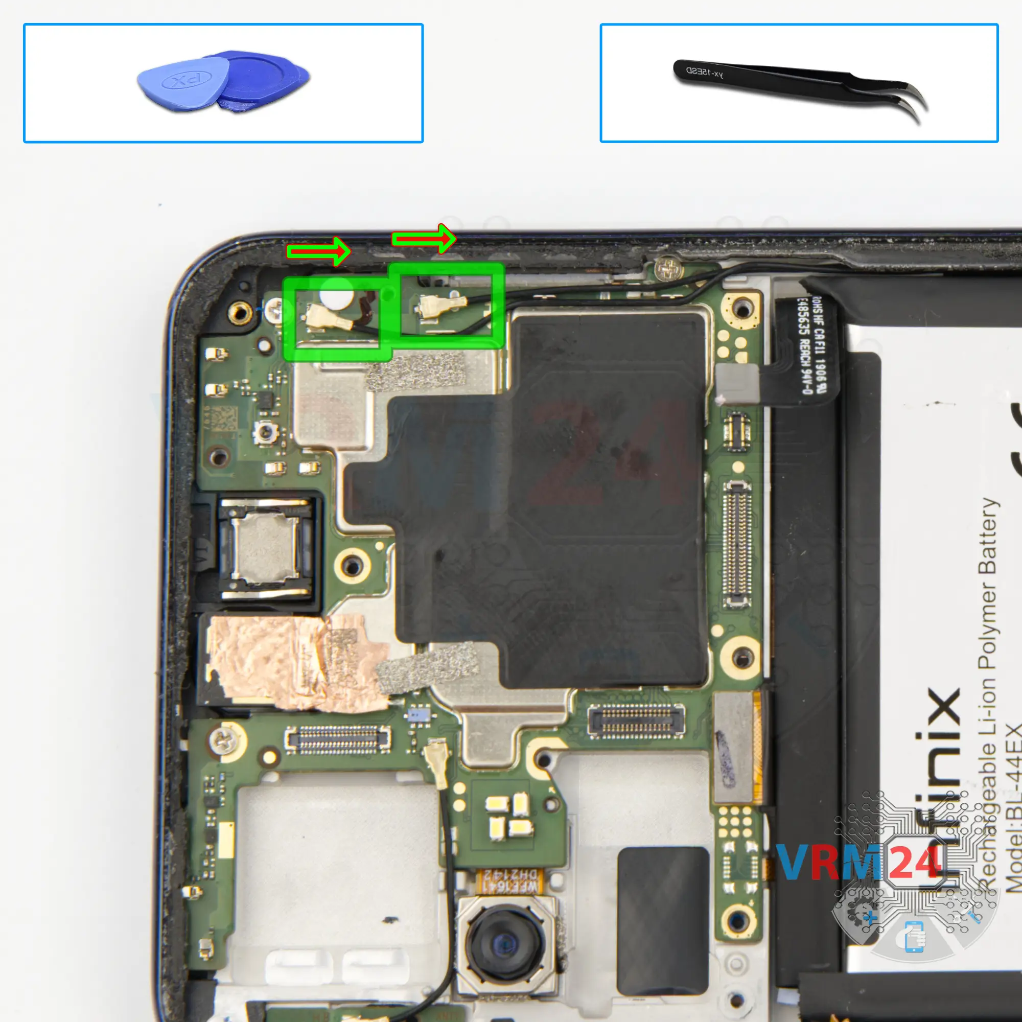
We disconnect the two connectors of the two coaxial cables and release the cables themselves from the clips fixing them on the motherboard.
Step 22.
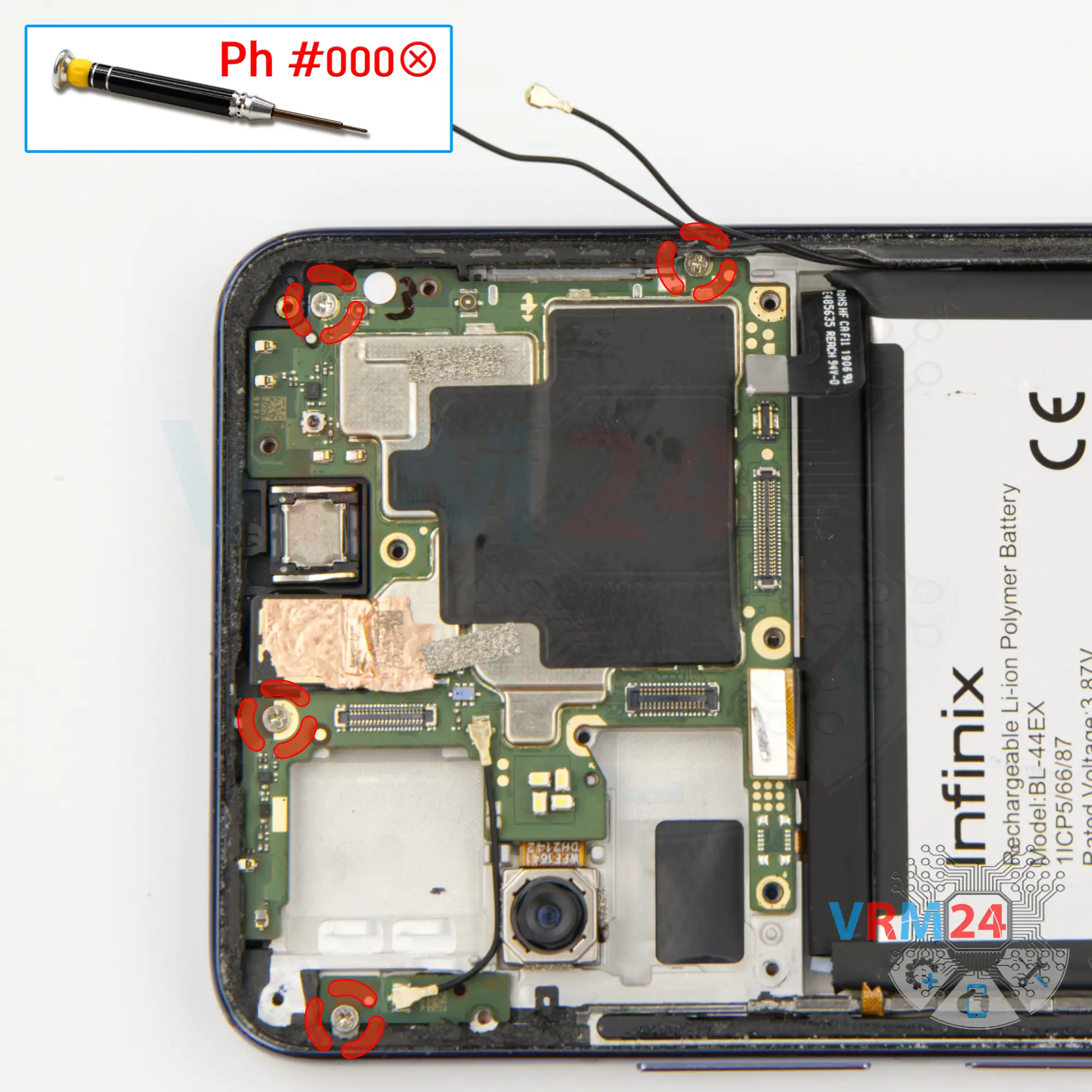
Unscrew the screws
And we unscrew the four screws securing the motherboard. The screwdriver is the same 1.5mm Phillips screwdriver.
⚠️ The screws are also different from the previous ones, so it is really important not to mix them up when reassembling.
Step 23.
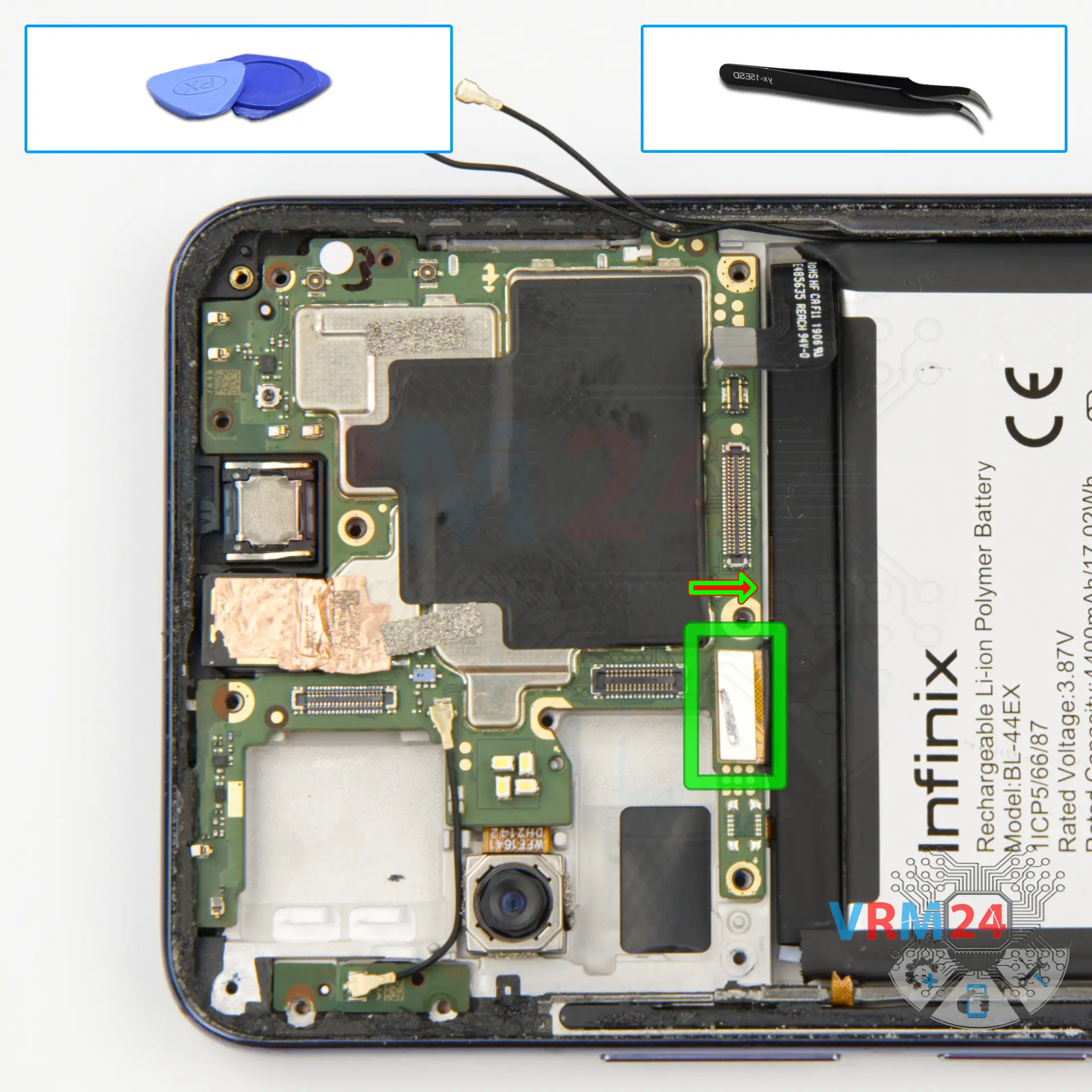
Disconnect the connector
And we move on to disconnecting the display connector on the motherboard.
Step 24.
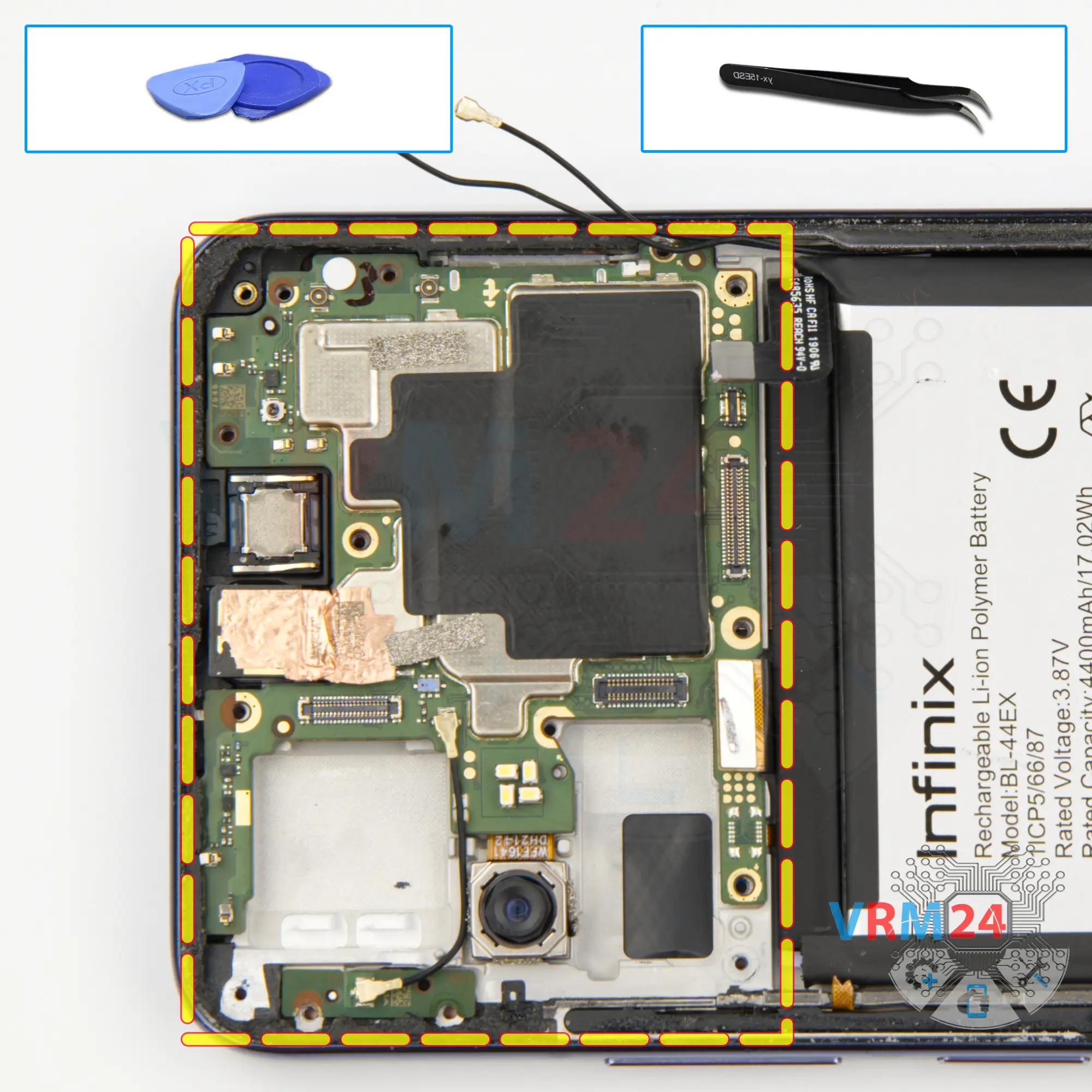
Remove the motherboard
Finally, we can detach the motherboard. We also need to find the right place where we can pry it up and lift it.
As we can see the motherboard is held in the rear camera area. We need to carefully detach the rear camera from the display frame.
Step 25.
Remove the cameras
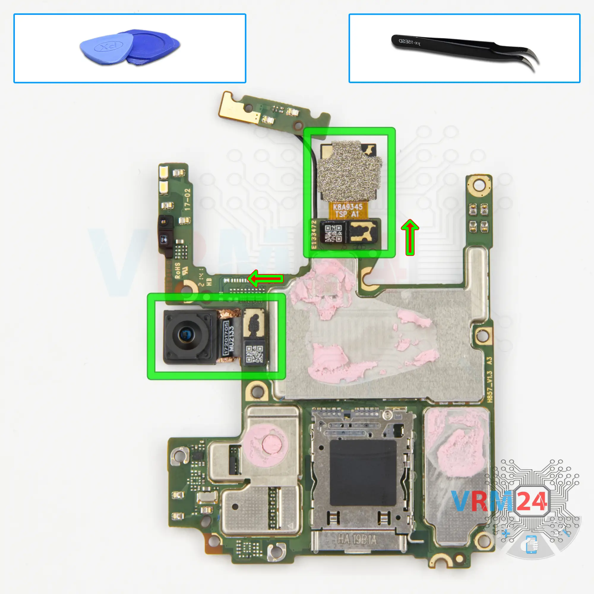
We turn over the printed circuit board. And we have to detach the front and rear cameras, but be extremely careful not to get thermal paste on the lenses when removing the cameras. We detach one front camera and one rear camera.

If you have a question, ask us, and we will try to answer in as much detail as possible. If this article was helpful for you, please rate it.

4246
Views
3
Likes
—
Share
0
Questions
Related Instructions
Related Reviews
Related Blog
Popular Questions
Lenovo Tab 4 TB-8504X
Is the tape that is over metal plate needed? It is a special kind of tape? What can I use if it was thrown away?
regina
T
ZTE Nubia Z11
sir my nubia z11 charging slot damaged one person make fraud saying that we must open display to change c type pin n display breaks in compulsorly n …
Tarun Electricals2
T
Sony Xperia XA
can i replace its camera ? a better one if possible? thanks
Tushar Hossain1
P
Samsung Galaxy Ace 4 Neo SM-G318H
you are removing the screen without heating it how can that be you crazy
Paulo Araujo15
B
Samsung Galaxy A6 Plus (2018) SM-A605
Does the screen necessarily break like on the A6 and J6??
body body4Top instructions
Check our
Top Infinix instructions most liked by readers
New instructions
Check our
New Infinix brand instructions on vrm24.com