⚠️ Before disassembling, do not forget to turn your phone off.
Teardown difficulty:
Easy
Easy
Duration:
10 min
10 min
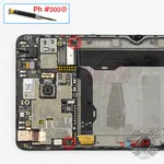
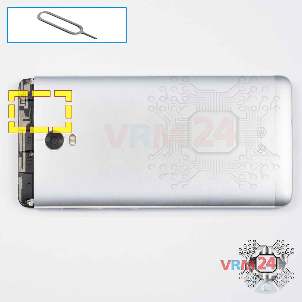
Recommended tools


Disassembly/Repair of the mobile device Lenovo Vibe P1 (Lenovo Vibe P1 P1c58) with each step description and the required set of tools.


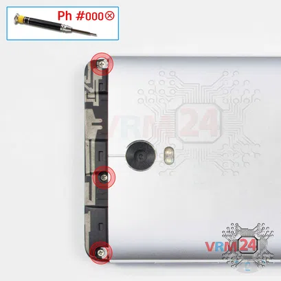
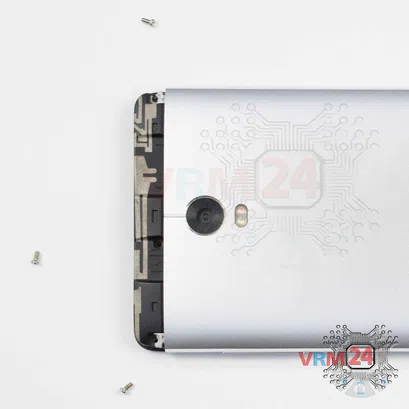

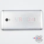
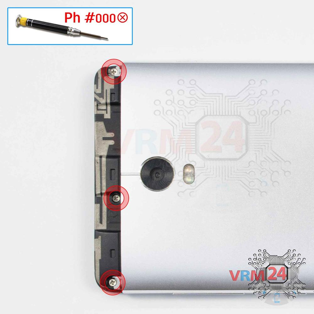
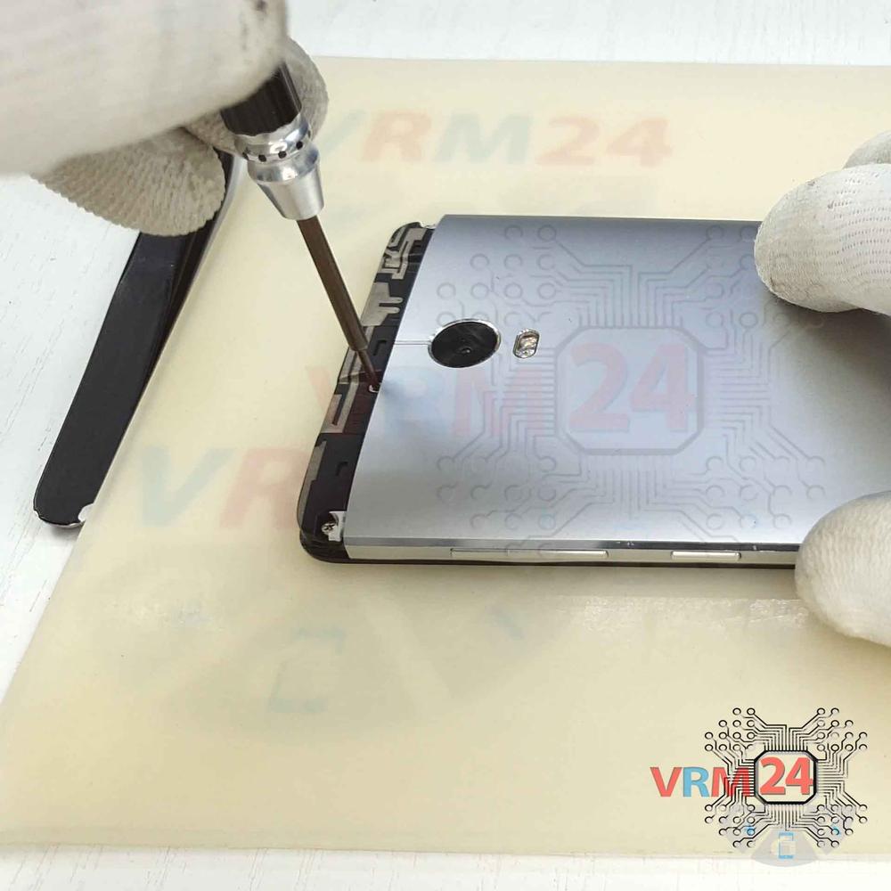
Step 4. Unscrew the screws
Using a screwdriver (Phillips 1.5 mm PH000), unscrew the three screws securing the back cover.

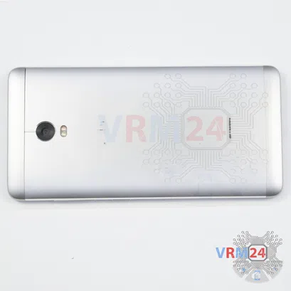
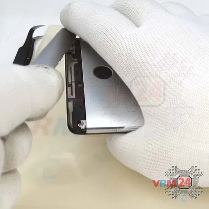
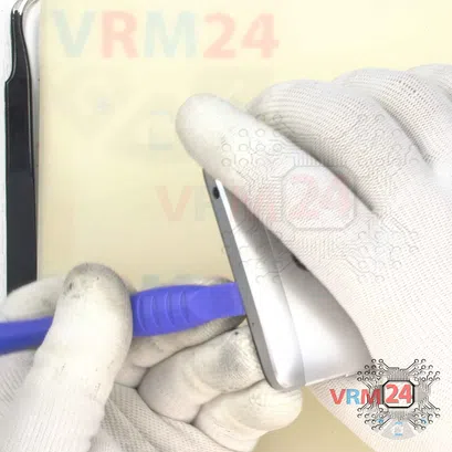
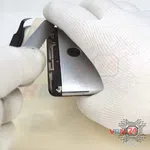
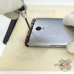
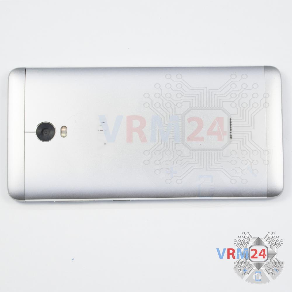
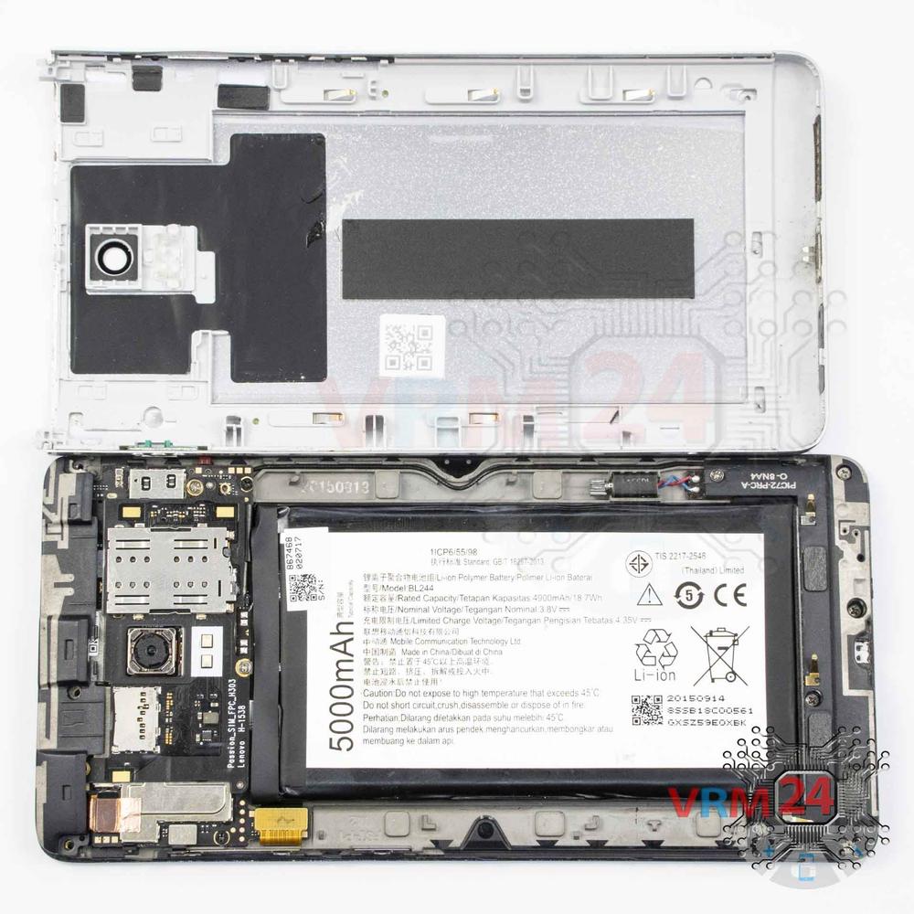
Step 5. Open the back cover
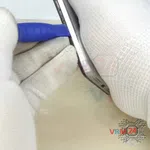
Using a spudger or a plastic pick, carefully, around the edge, detach the back cover clips, and remove it.
Do not insert the tool deeply or bend it. Otherwise, the housing may be tampered with or damaged.
⚠️ Be careful when opening the cover from the volume and power buttons side. Thin cable and fragile buttons are straightforward to damage.
⚠️ Look in advance in the picture for the cables’ location for inter-board, touchscreen, display, buttons (if any) under the cover to not damage them accidentally.


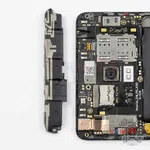
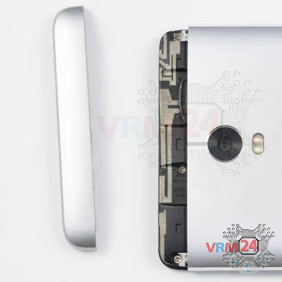
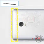
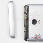
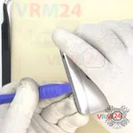
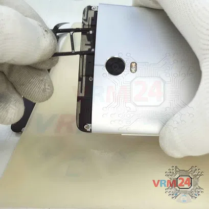
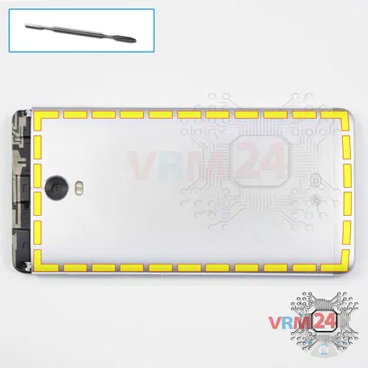
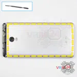
Step 6. Open the cover
Remove the cover with antennas. Try to lift the covers by the edges and not push anything between them to not accidentally touch or short-circuit anything on the PCB.
ℹ️️ On the upper cover, you can see the metalized coating on the plastic in the form of tracks and contact pads. These are Wi-Fi, Bluetooth, and GPS antennas.
⚠️ It is crucial while reassembling, checking the spring contacts on the board, and the contact pads on the cover match and touch. Otherwise, signal loss or signal may be quite weak.
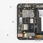
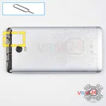
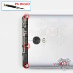
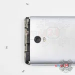
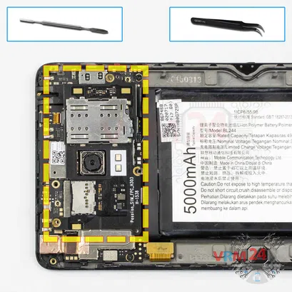
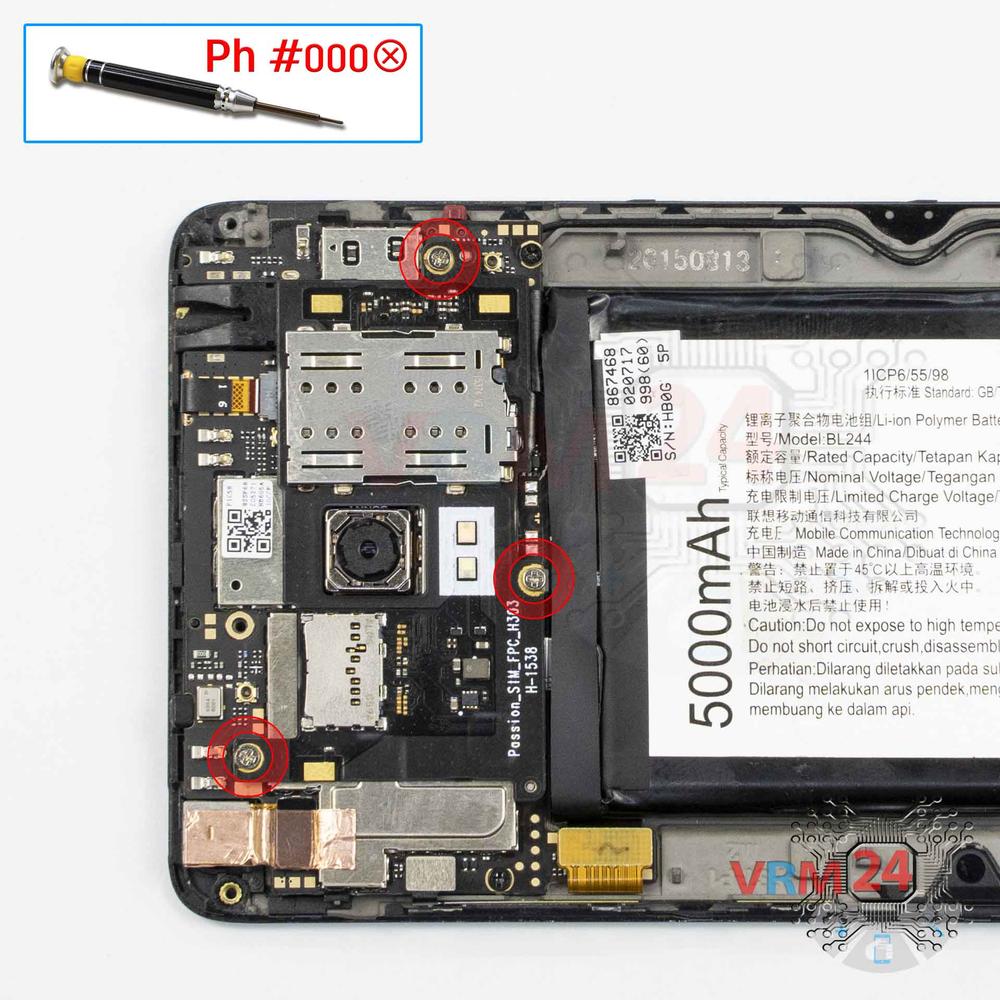
Step 7. Unscrew the screws
Using a screwdriver (Phillips 1.5 mm PH000), unscrew the three screws securing the motherboard.
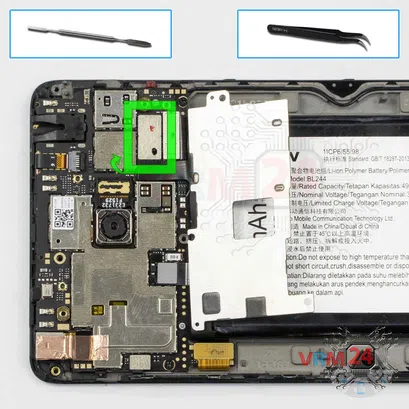
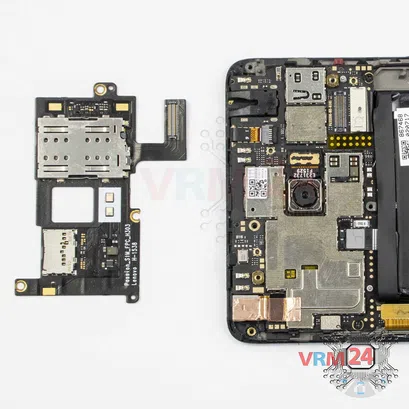
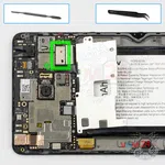

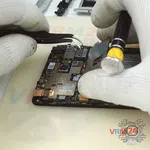
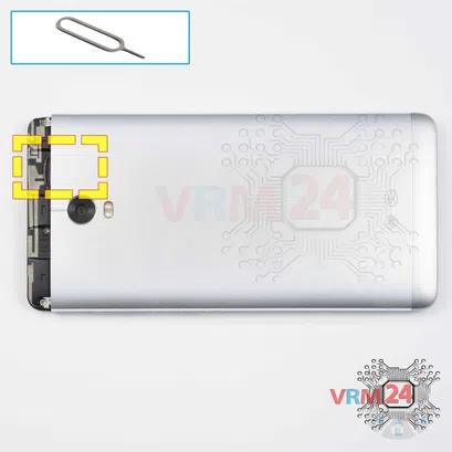
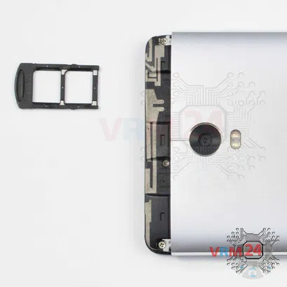
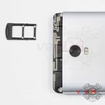
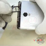
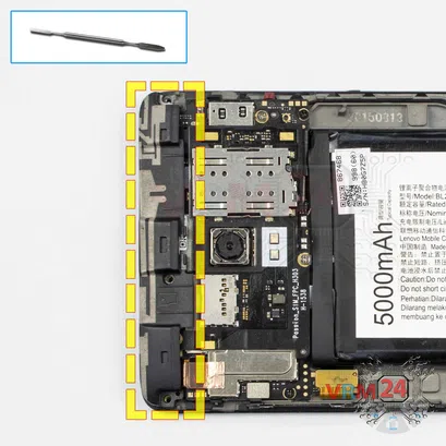
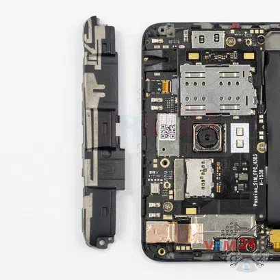
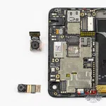
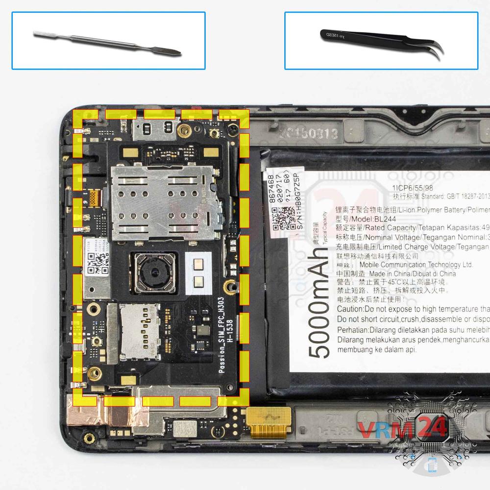
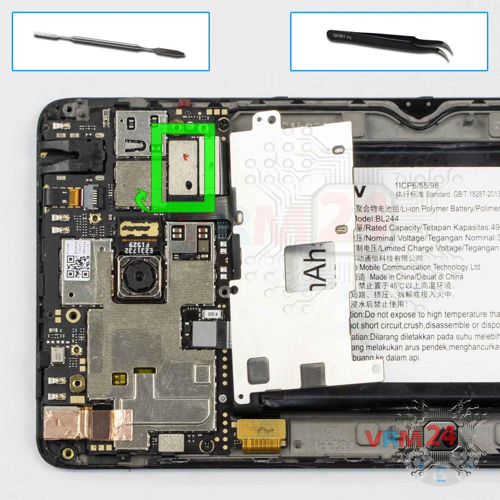
Step 8. Remove the small board
Turn the upper board with card holders and flash out. Disconnect the connector and remove the board.
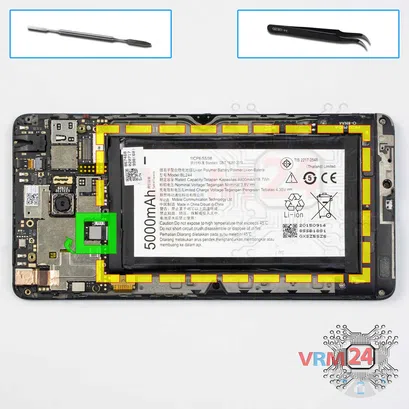
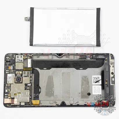
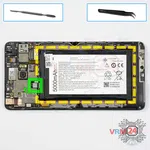
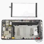
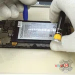
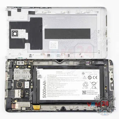
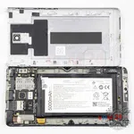
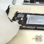
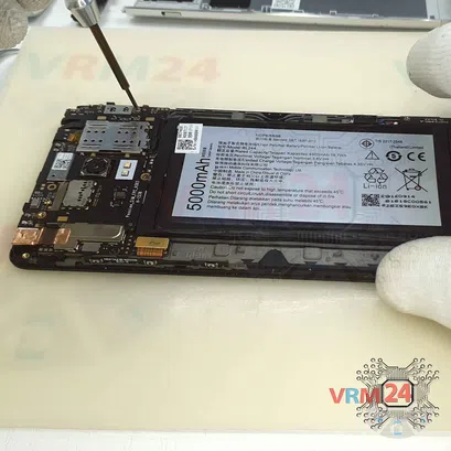
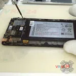
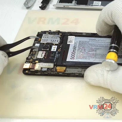
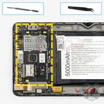
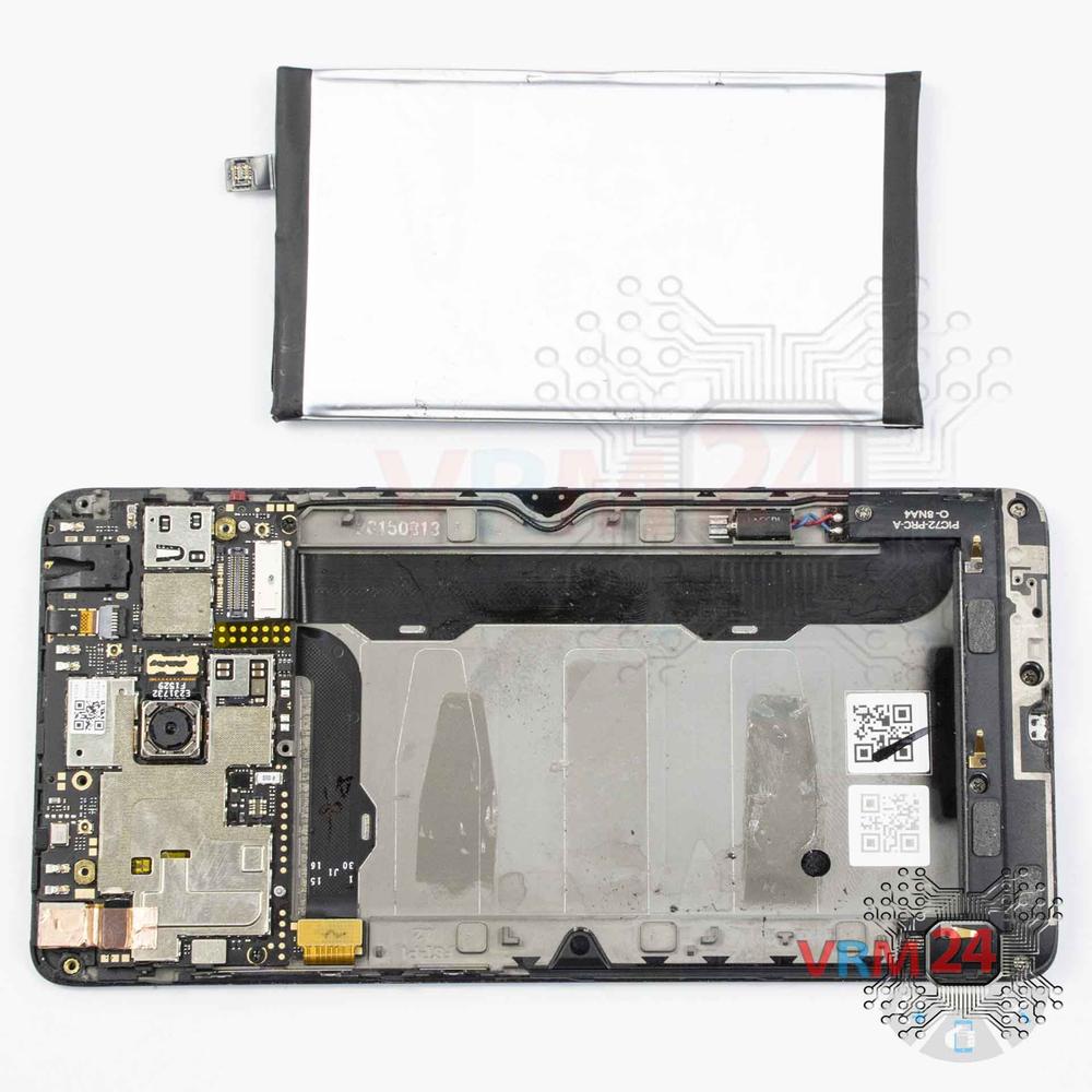
Step 9. Remove the battery
Disconnect the connector and remove the battery.
ℹ️️ The Lenovo Vibe P1 (P1c58) model has a battery BL244 with 5000 mAh capacity (aka rechargeable battery).
⚠️ It is highly recommended to disconnect the connector to avoid possible short circuits during disassembly. Also, try not to use a metal tool to disconnect the rechargeable battery connector or do it carefully.
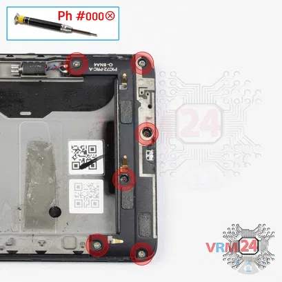

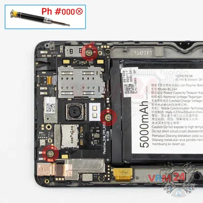
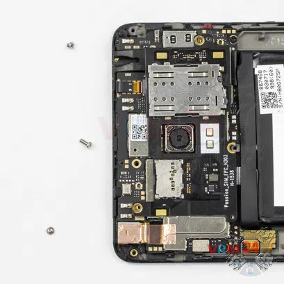
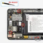
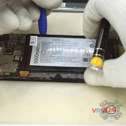
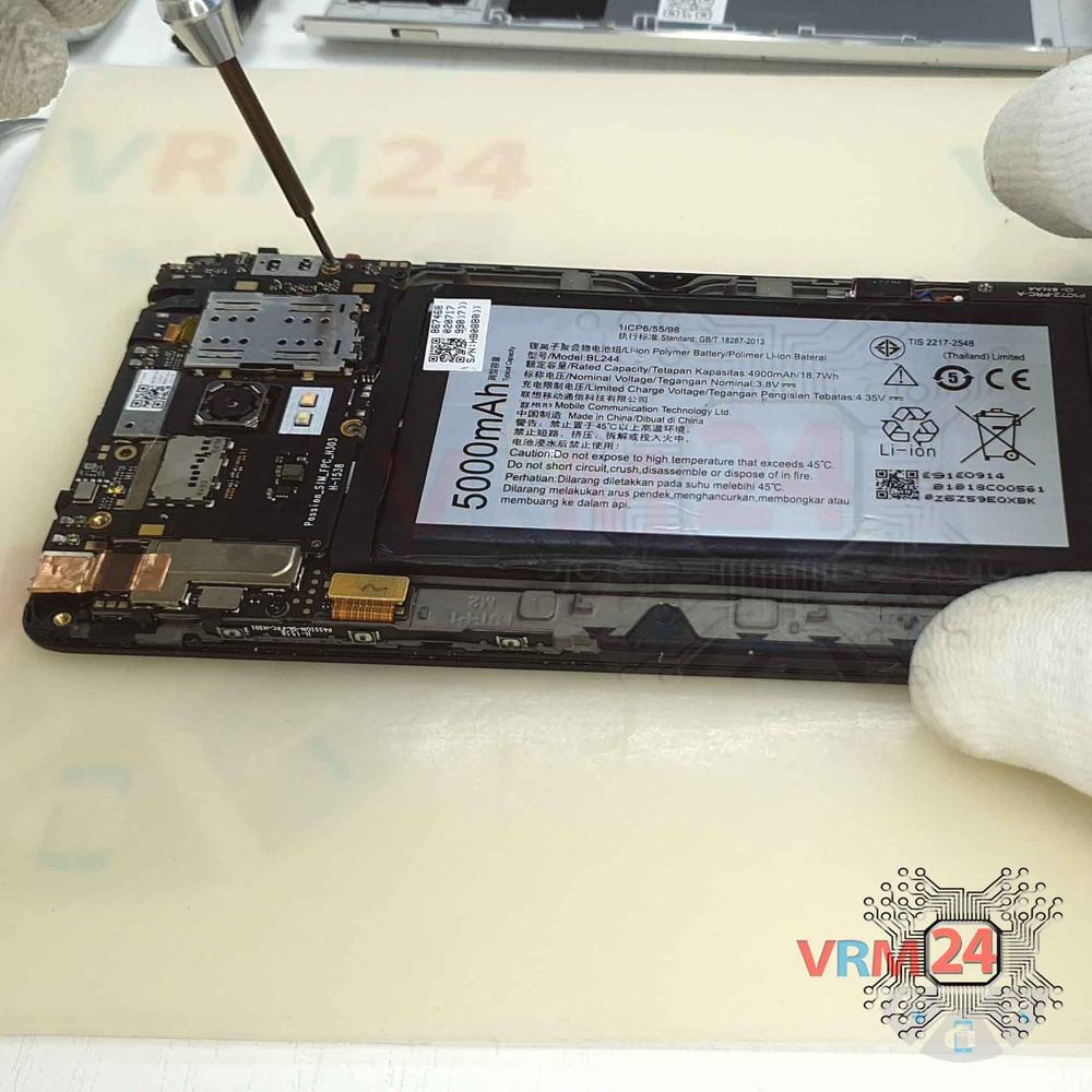
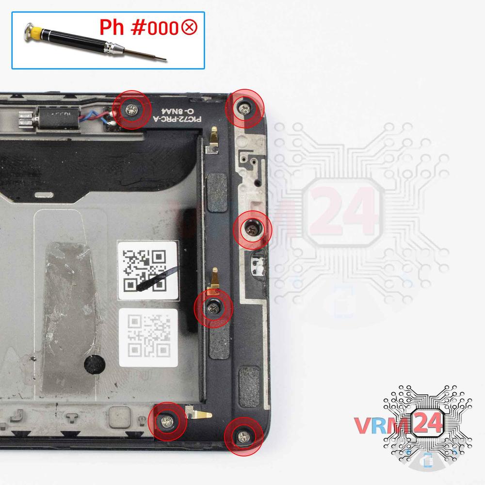
Step 10. Unscrew the screws
Using a screwdriver (Phillips 1.5 mm PH000), unscrew the six screws.
ℹ️️ Be sure to note the location of the screws before disassembling. When assembling the device, screwing the screw in the wrong place may damage the device or its parts. To avoid damage, the removed screws and individual pieces (as gaskets or brackets) must be laid out in the appropriate order, or the screws and their holes in the phone must be marked with colored markers.


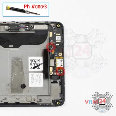
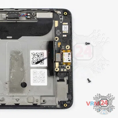
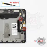
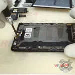
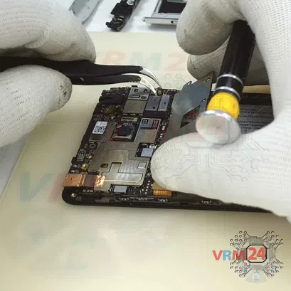
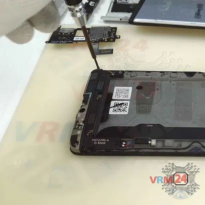
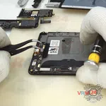
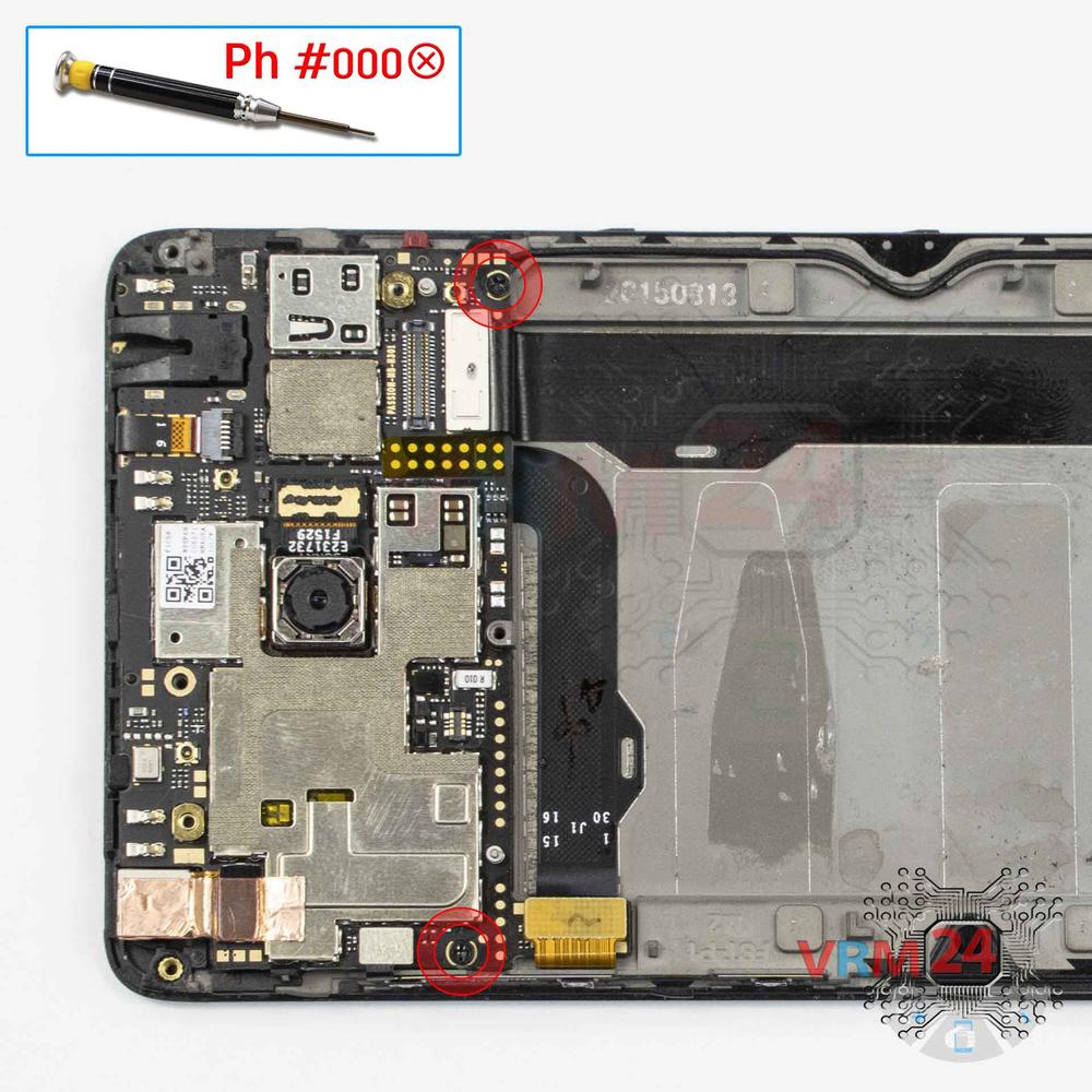
Step 12. Unscrew the screws
Using a screwdriver (Phillips 1.5 mm PH000), unscrew two screws securing the daughterboard.
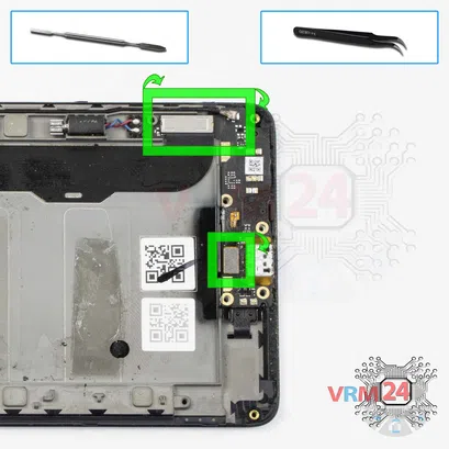
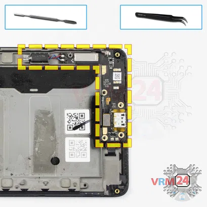
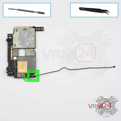
Step 13. Disconnect the connectors
Disconnect the coaxial cable connector, cables to the mainboard, and inter-board sub-screen cable on the daughterboard.
⚠️ Do not pull on the cable or pry it with a sharp tool, the connectors are pretty weak and break easily, or the cable falls out of the end (lug).
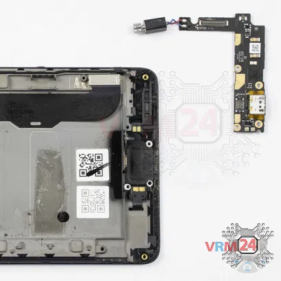
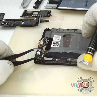
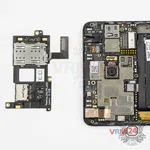
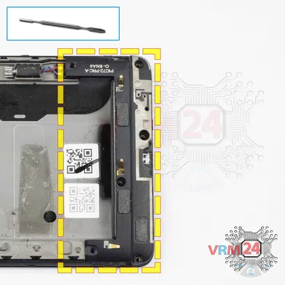
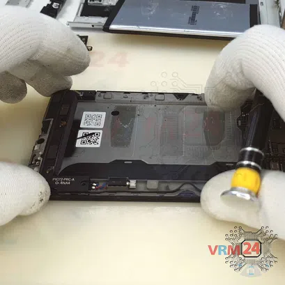
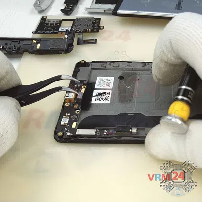
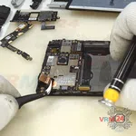
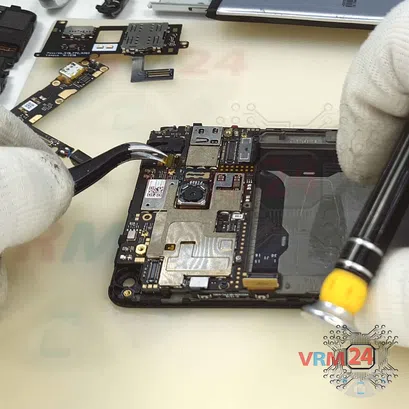
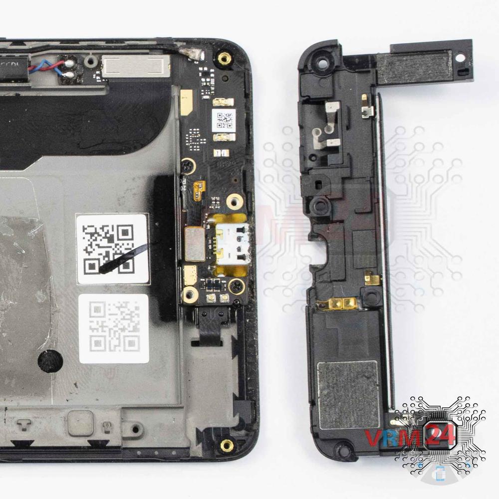
Step 14. Remove the sub-board
Remove the sub-board. It is glued to the frame with metalized tape, so to facilitate the process, the board can be heated a bit.
ℹ️️ The board contains a charging port (Micro USB), microphone, vibration motor, spring contacts for the speaker, and an antenna unit.
⚠️ It is not necessary to insert the tool under the board when removing the sub-board. Internal components could be damaged.


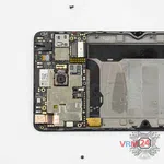
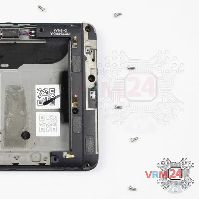
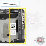
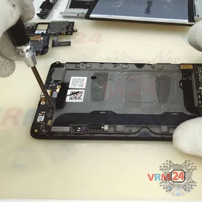
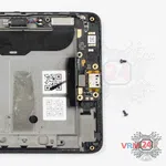
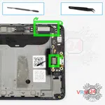
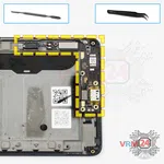
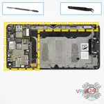
Step 15. Unscrew the screws
Using a screwdriver (Phillips 1.5 mm PH000), unscrew two screws.
ℹ️️ Be sure to note the location of the screws before disassembling. When assembling the device, screwing the screw in the wrong place may damage the device or its part. To avoid damage, the removed screws and individual pieces (as gaskets or brackets) must be laid out in the appropriate order, or the screws and their holes in the phone must be marked with colored markers.


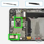

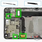
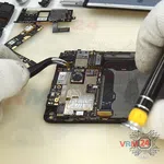
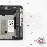
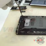
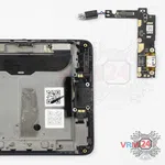
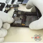
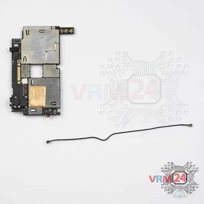
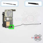
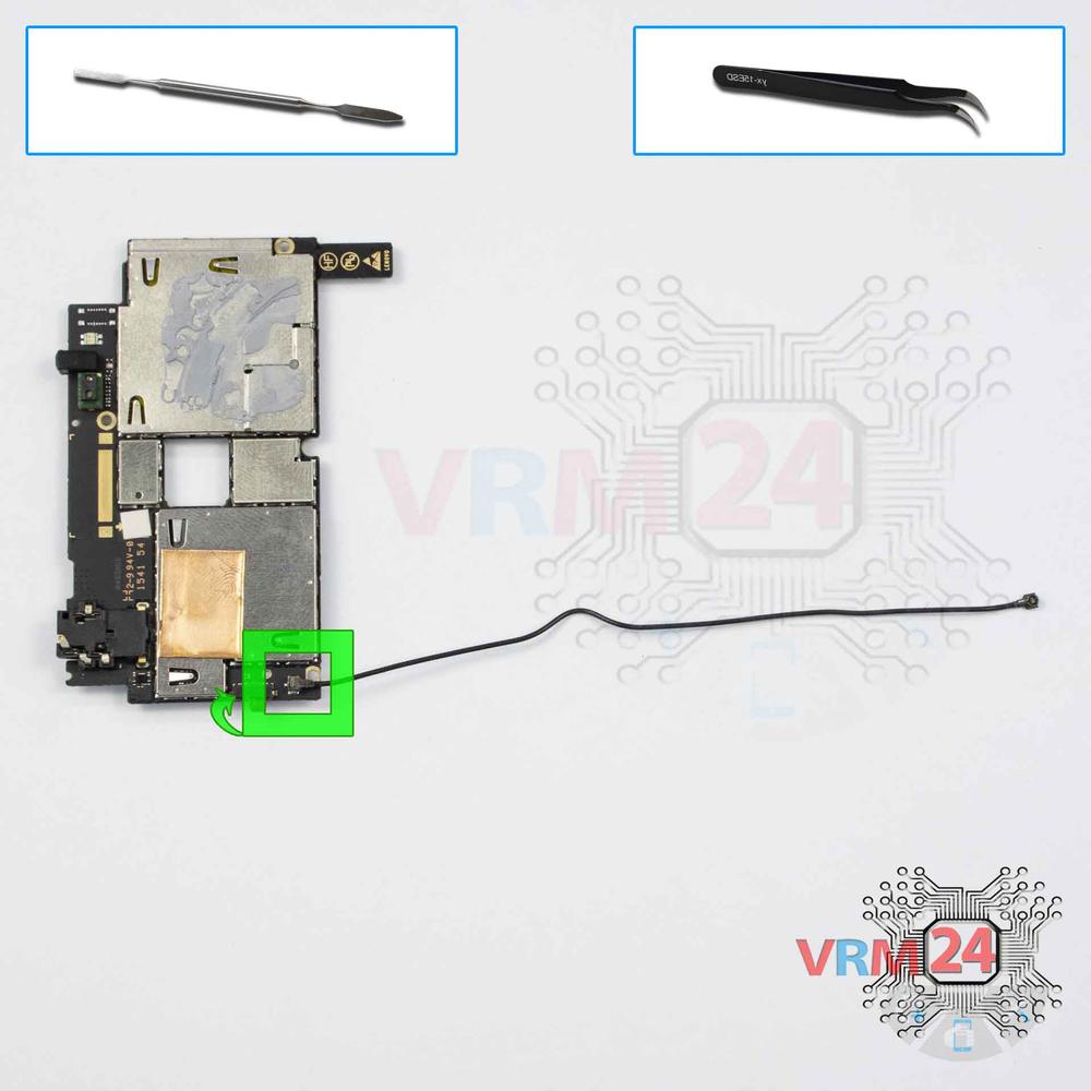
Step 17. Disconnect the connectors
Pry up the connectors of power volume buttons cable, display module cable, inter-board cable, and coaxial cable.
⚠️ Be careful when removing the cables from the connectors, the cables are pretty thin, and it is easy enough to break them or damage the contact tracks inside.
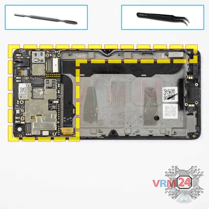
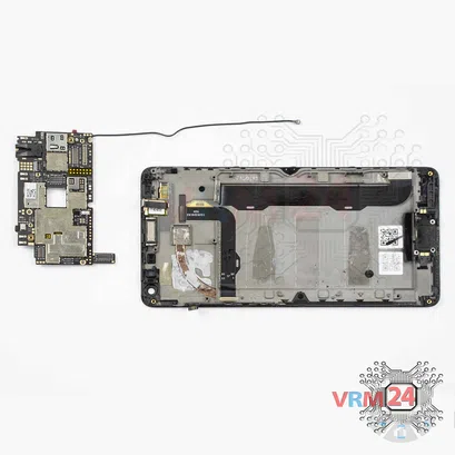
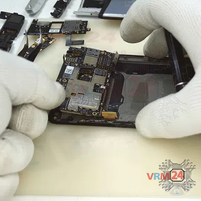
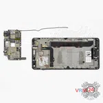
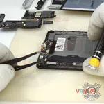
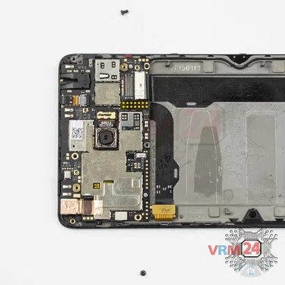
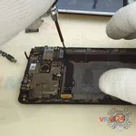
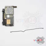
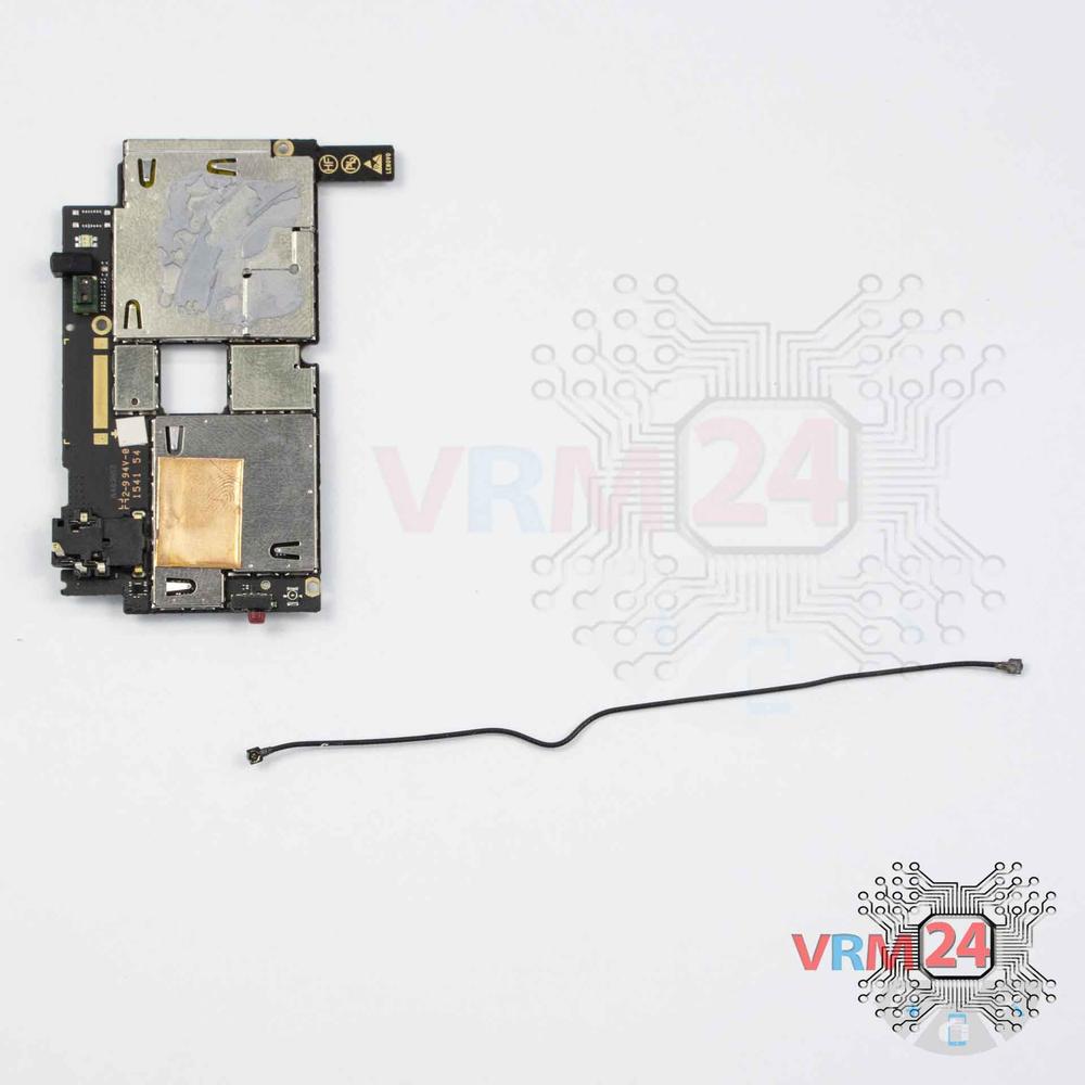
Step 18. Remove the motherboard
Carefully remove the printed circuit board. There is no need to use a lever or try to reach the board by force. Make sure that nothing is getting in the way or holding the board.
⚠️ Do not bend the circuit board when removing it or push tools under it. Unbeknownst to yourself, you can damage components or cables from the inside.
Detailed disassembly instructions of Lenovo Vibe P1 in the video, made by our mobile repair & service center:
If you have a question, ask us, and we will try to answer in as much detail as possible. If this article was helpful for you, please rate it.

Disassembling\Repair has easy complexity and takes about 10 minutes in time.
Our manual is suitable for all models Lenovo Vibe P1 — Lenovo Vibe P1 P1c58 released for markets in different countries.
Back to the list