
⚠️️ Before disassembling, do not forget to turn your tablet off.
Teardown difficulty:
Easy
Easy
Recommended tools


Disassembly/Repair of the mobile device Lenovo Yoga Pad Pro 13 (Lenovo Yoga Pad Pro 13 YT-K606F) with each step description and the required set of tools.

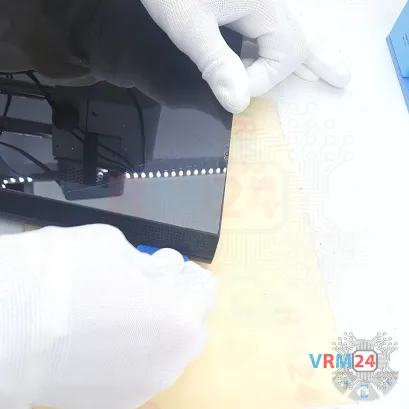


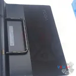
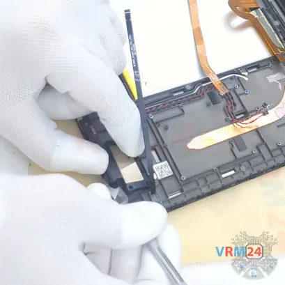
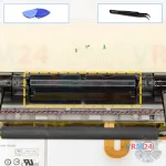
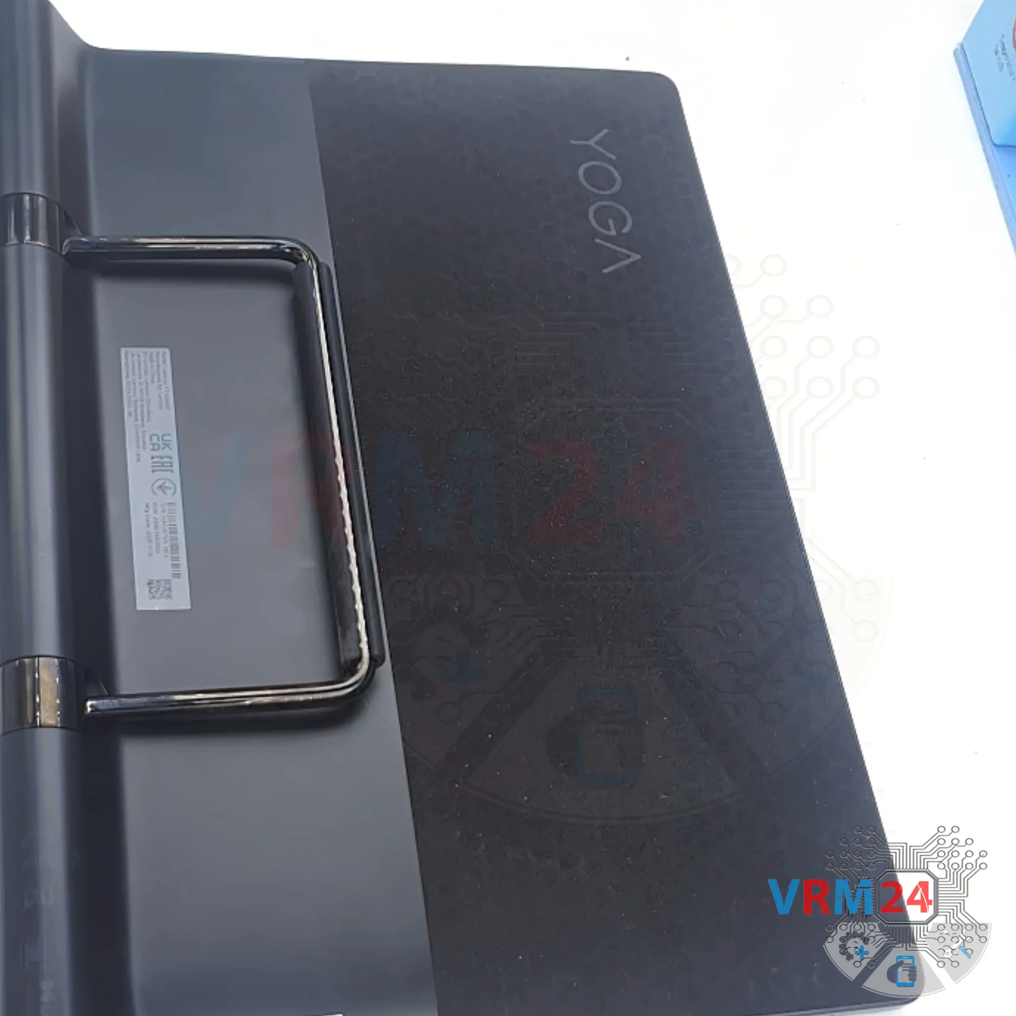
Step 2. Open the back cover
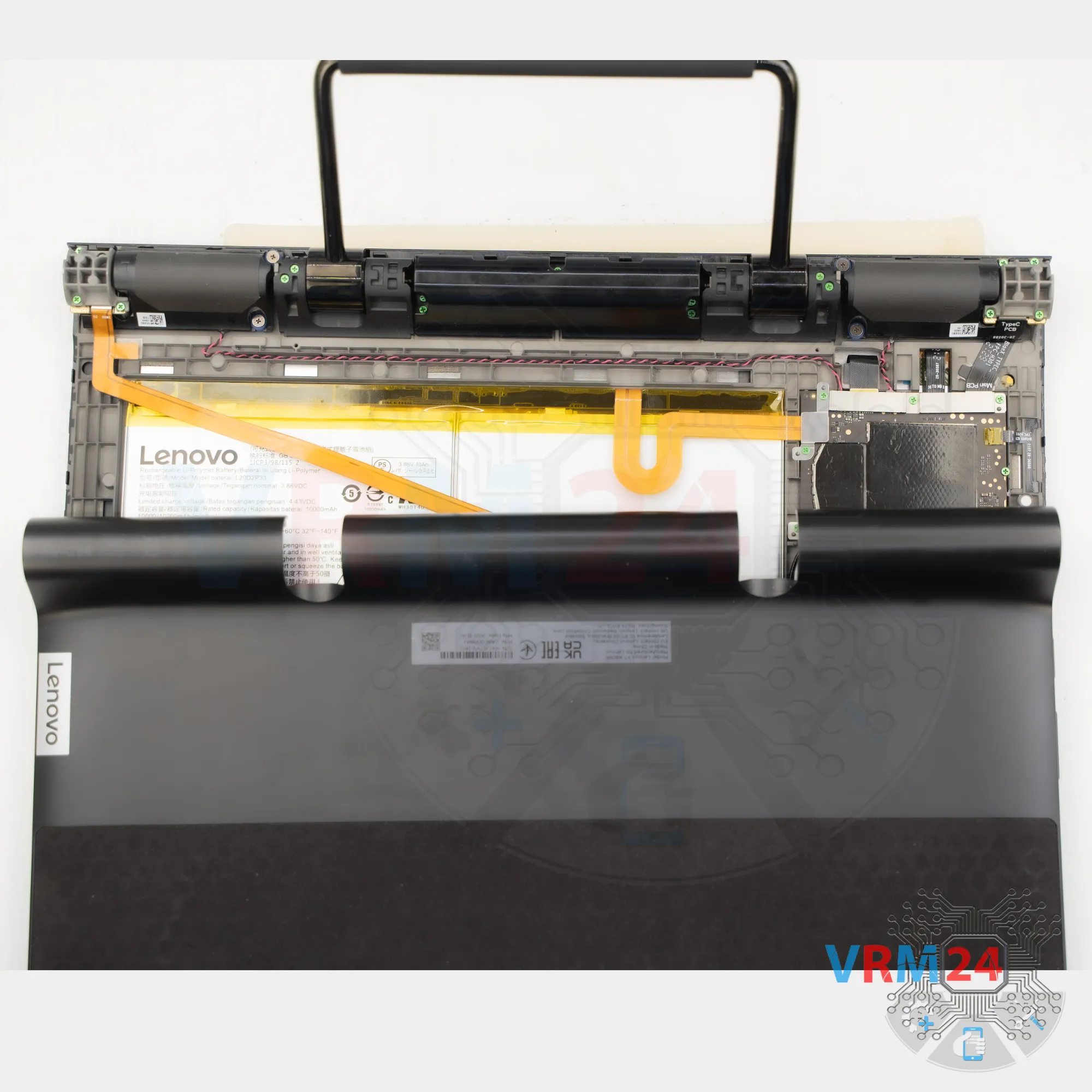
We’ll start by removing the back cover, or the housing.
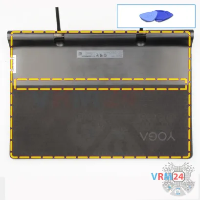
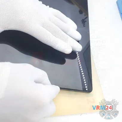
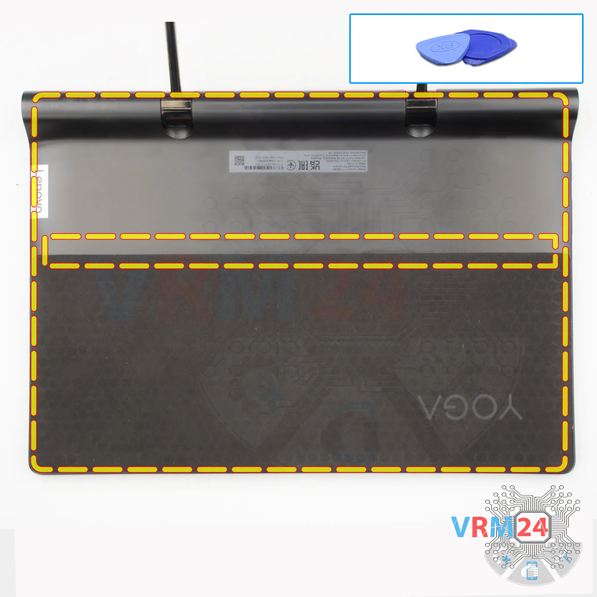
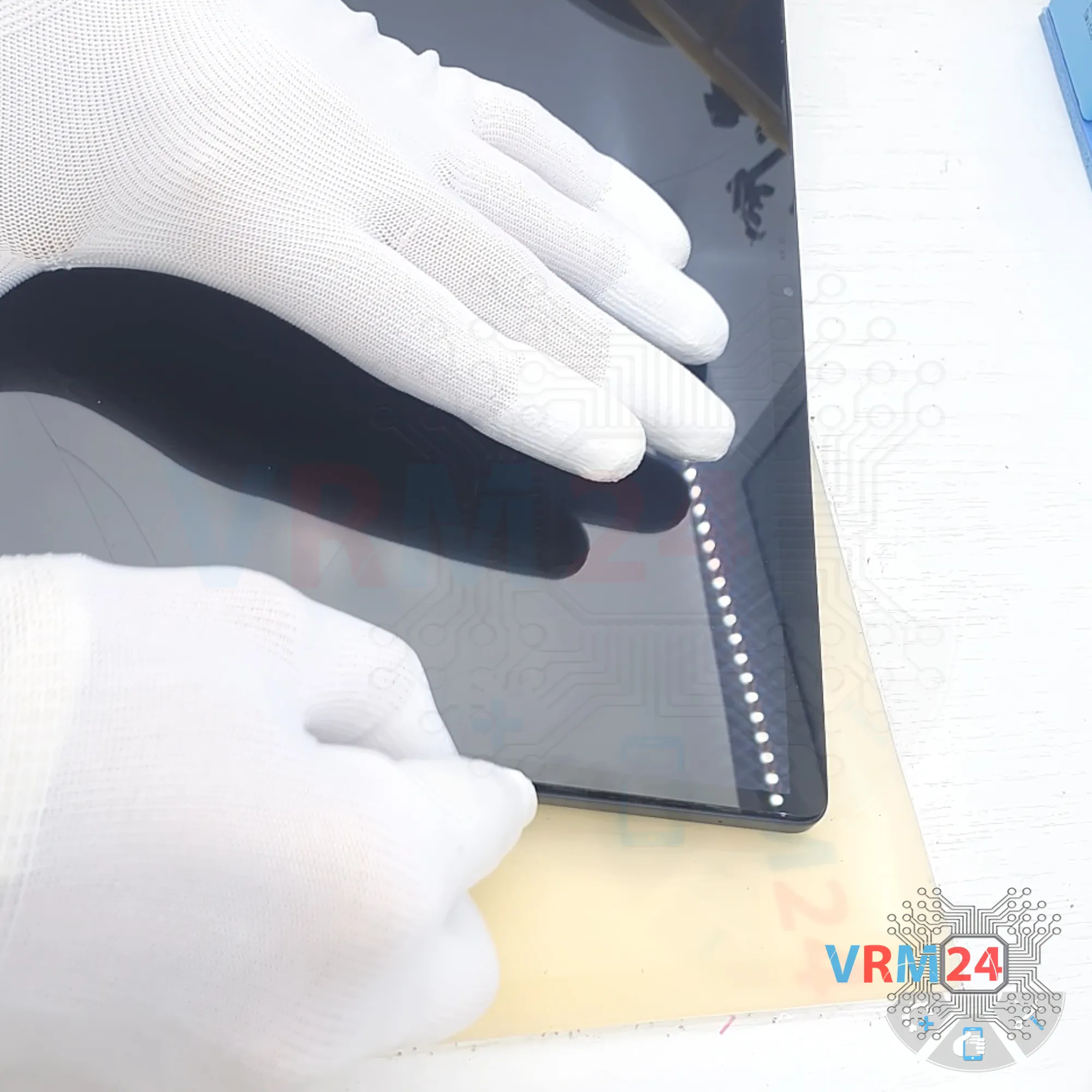
To do this, we use a thin plastic tool—insert it into the gap between the edge of the display and the back cover. Push the tool in carefully, deep enough so you don’t accidentally touch or damage the display edge. Then, release the clips.
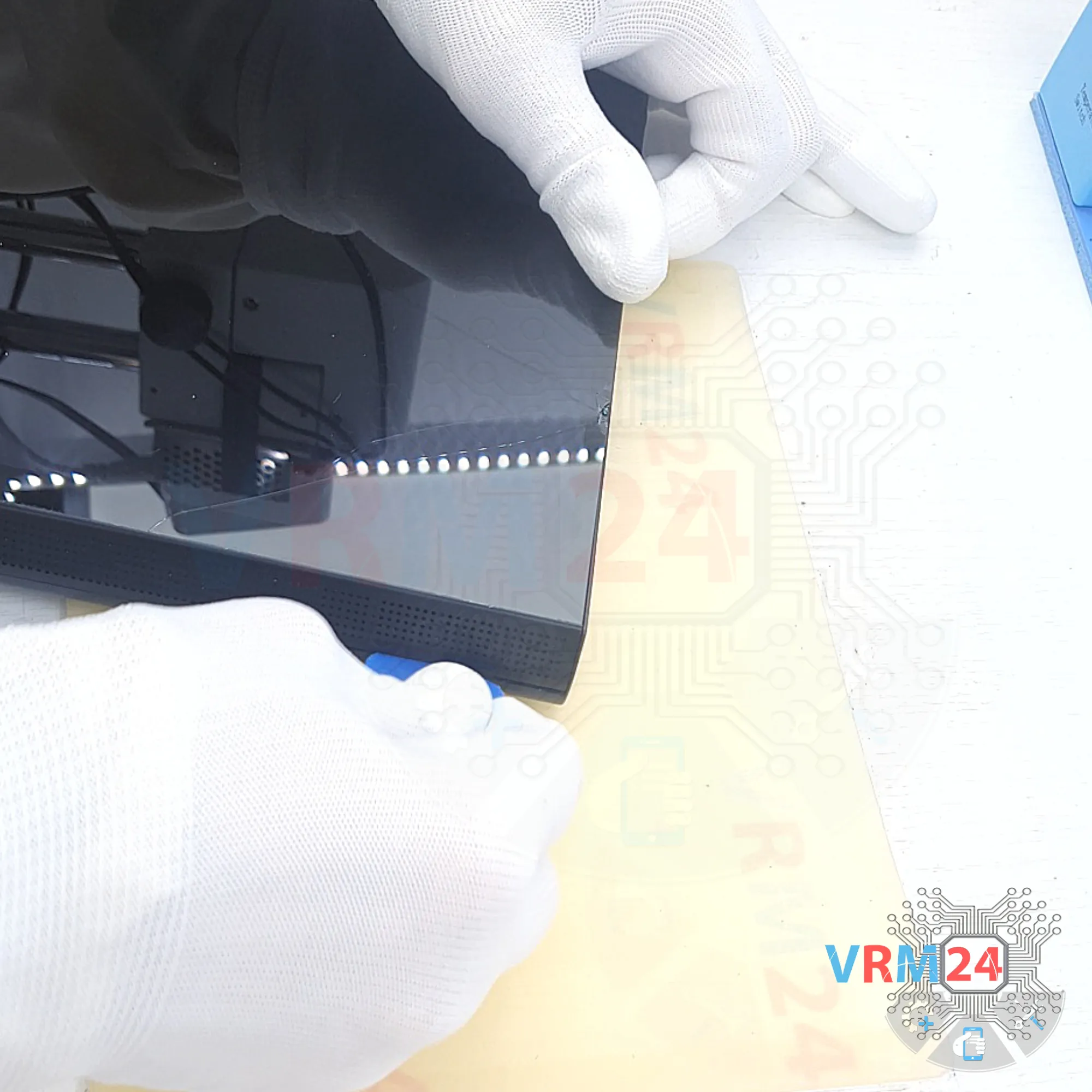
Work carefully along the edges—the clips come off fairly easily.
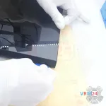
If something is blocking you, don’t force it. Take a careful look at what is coming loose and what isn’t.
By the way, some clips are also located in the middle part.


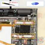
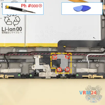
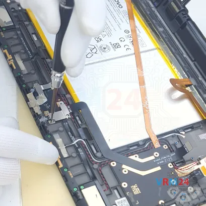
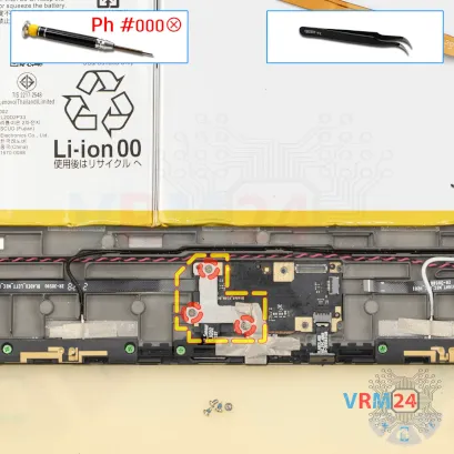
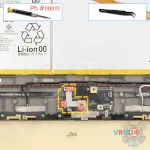
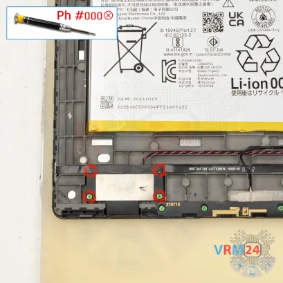
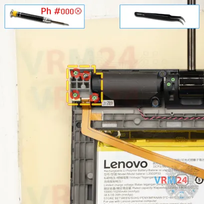
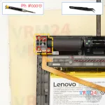
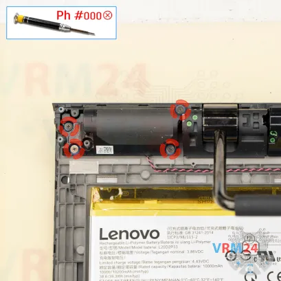
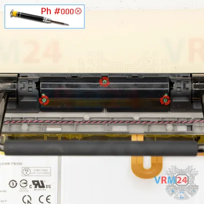
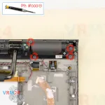
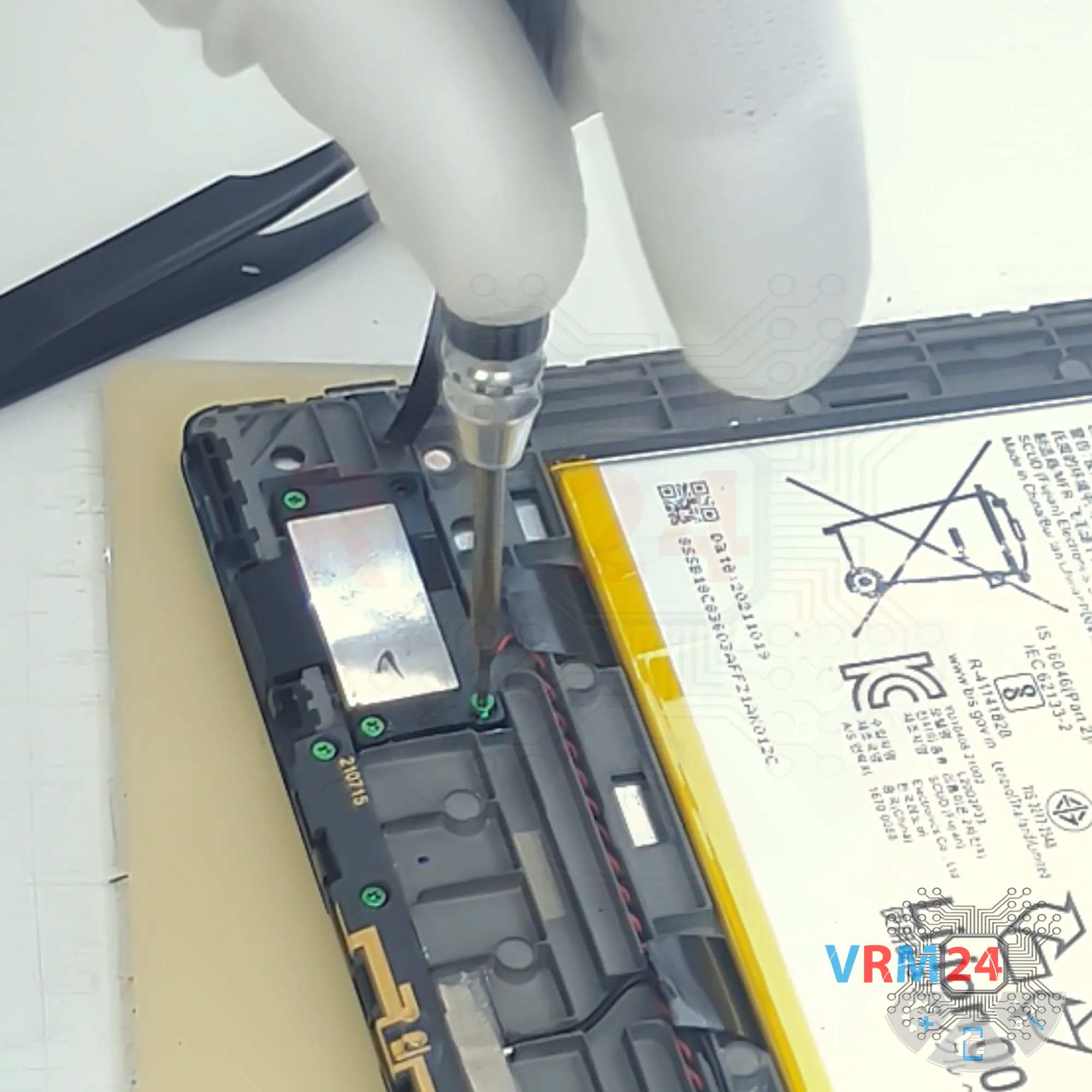
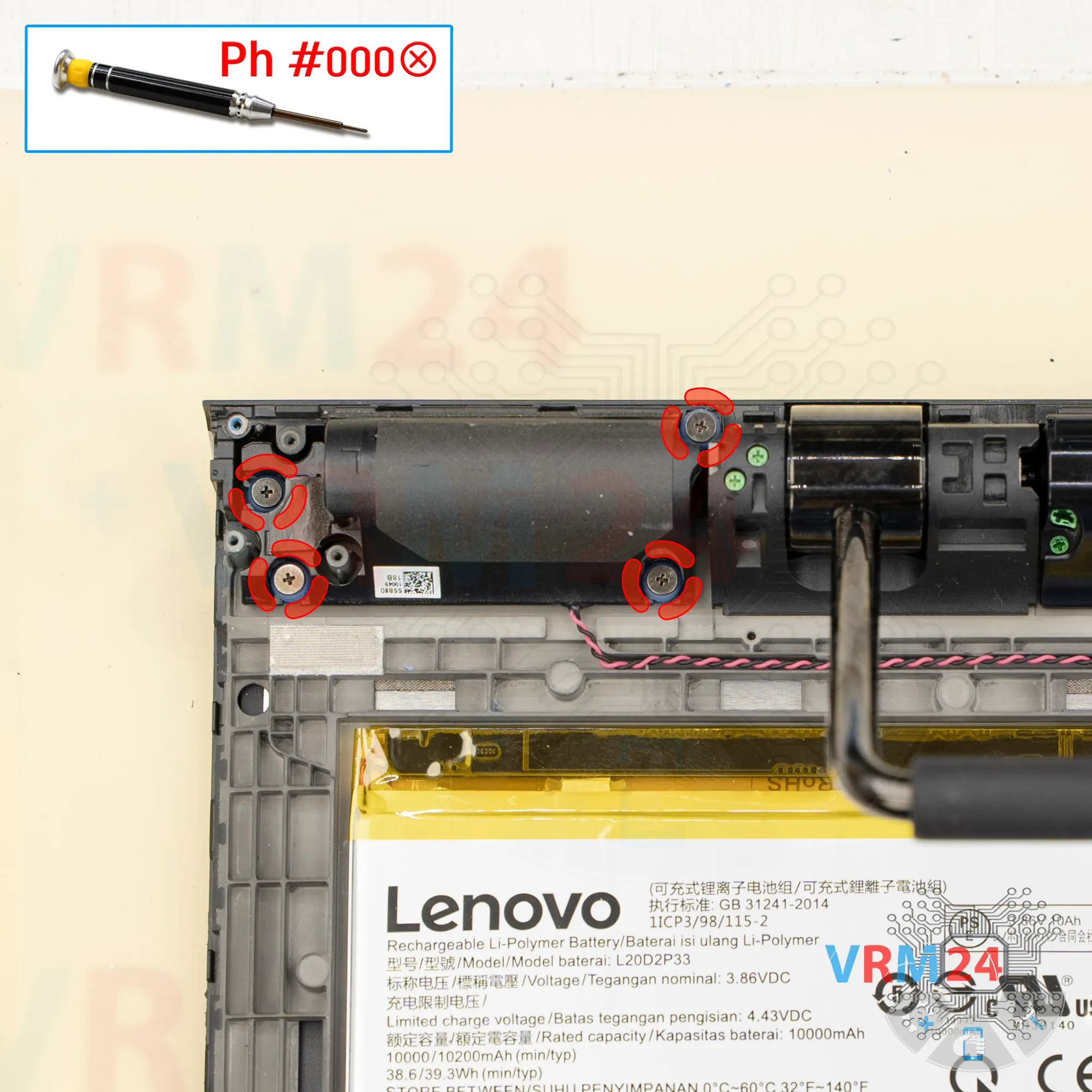
Step 3. Unscrew the screws
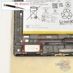
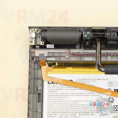
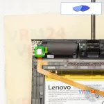
Next, we move on to unscrewing the two screws that hold the battery connector in place.
For this, we use a 1.5 mm Phillips screwdriver, or a Phillips #000.

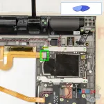

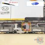
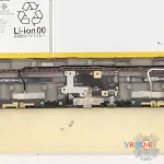
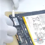
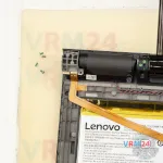
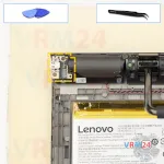
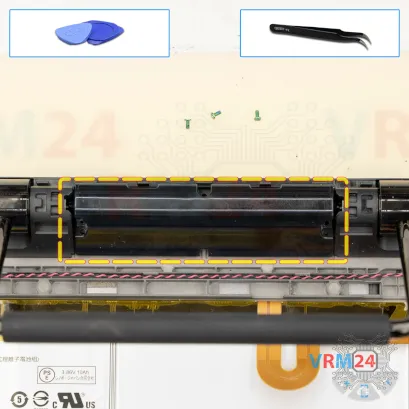
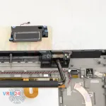
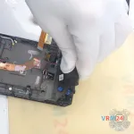
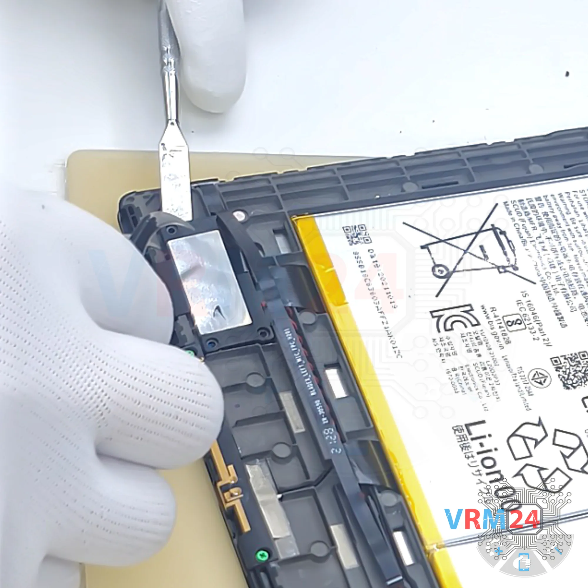
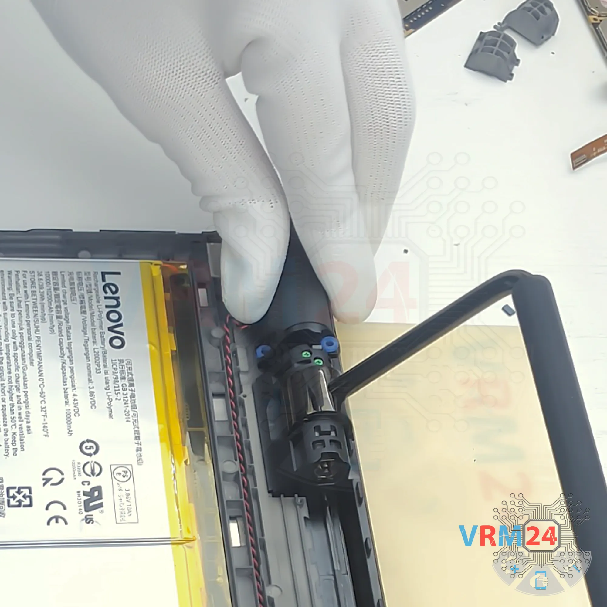
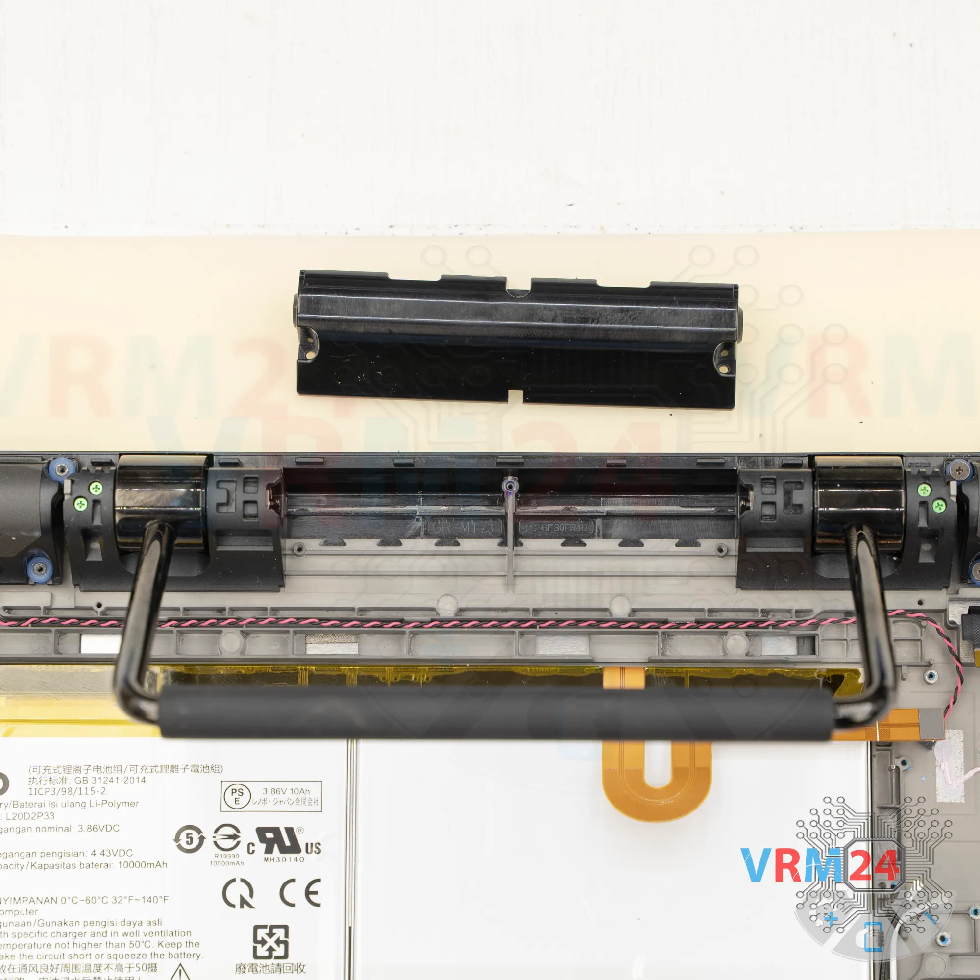
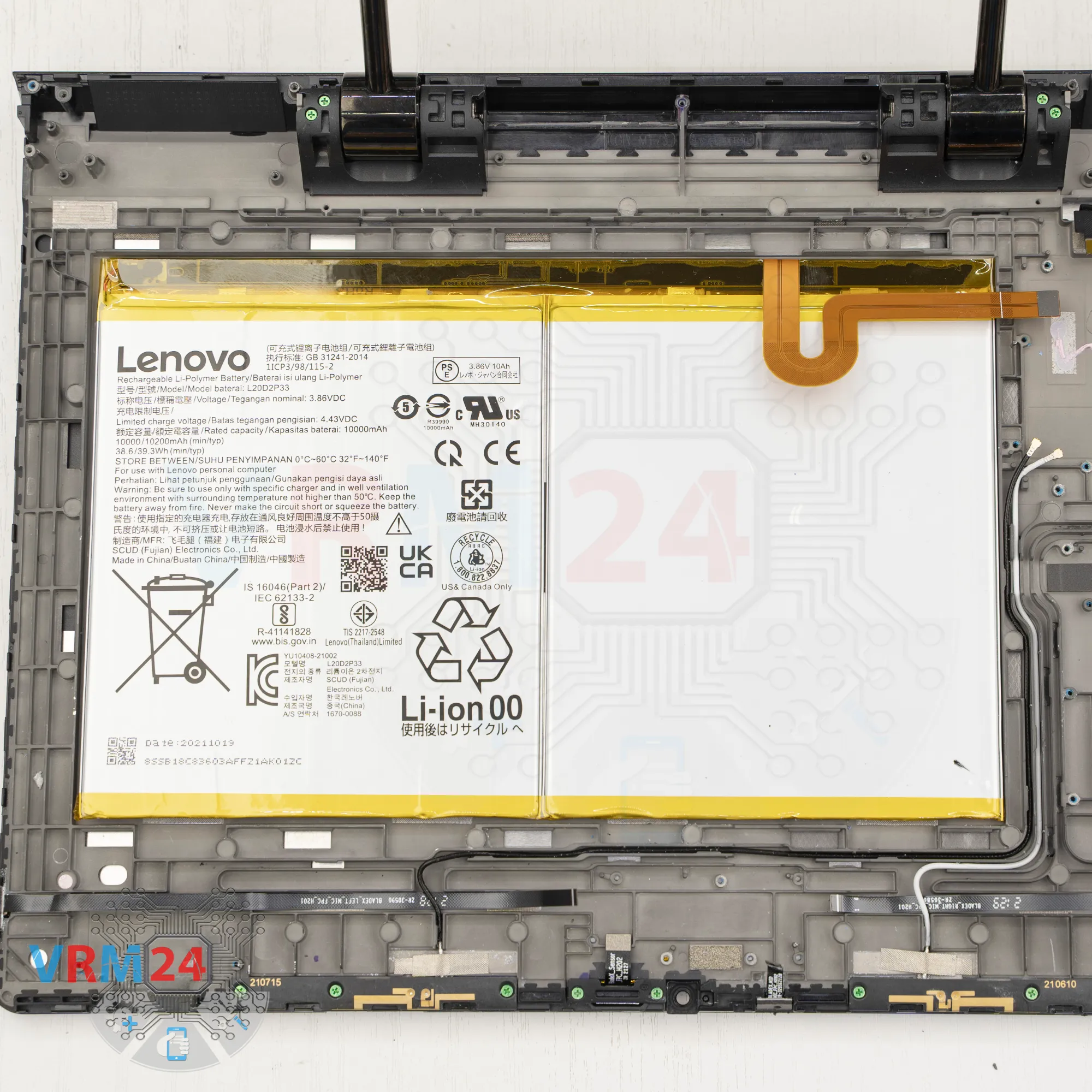
Step 4. Disconnect the battery connector
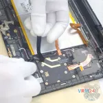
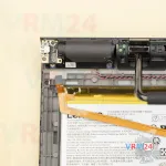
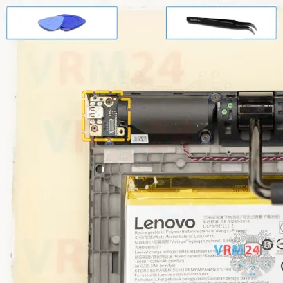
Then, using a non-metal tool, we need to disconnect the battery connector.
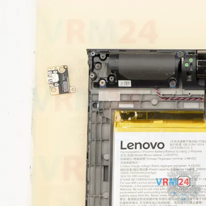
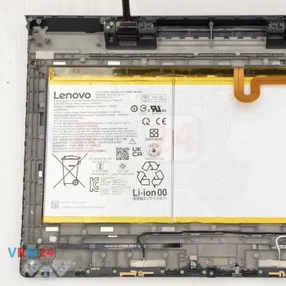
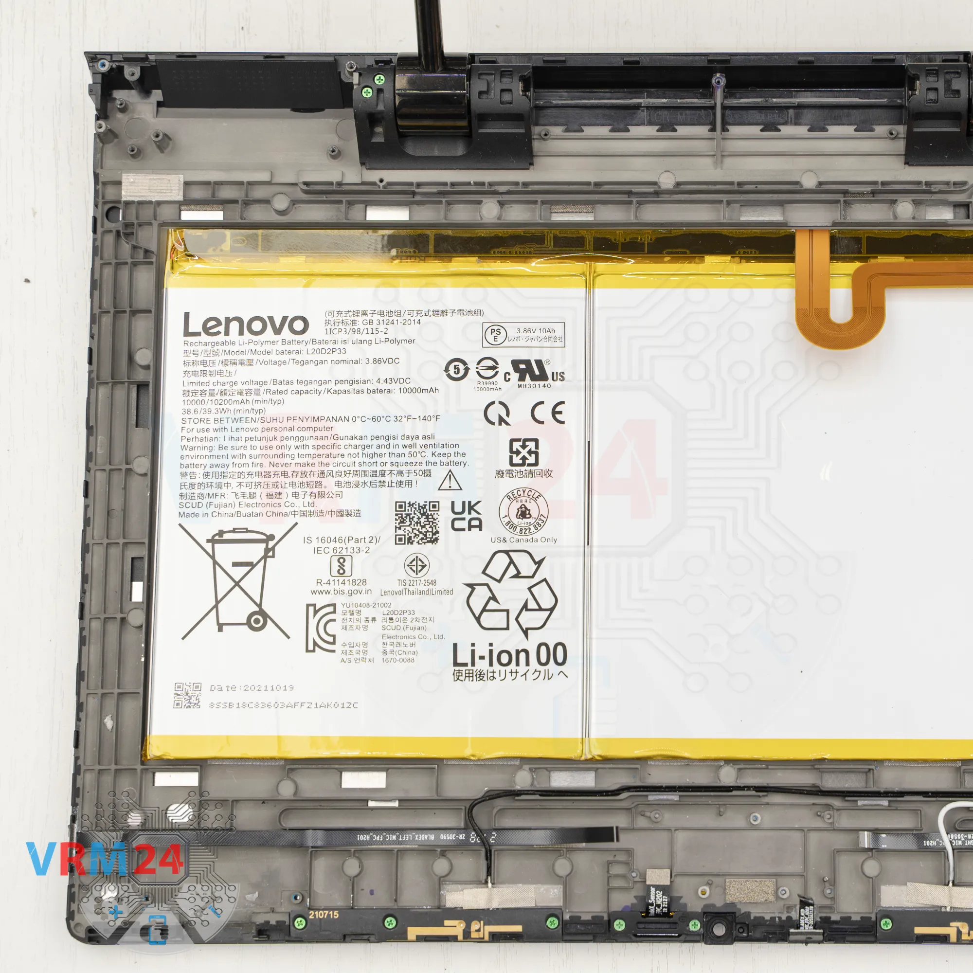
ℹ️️ The Lenovo Yoga Pad Pro 13 YT-K606F uses a L20D2P33 rechargeable battery with a capacity of 10000 mAh.
Disconnect the battery connector and continue working.
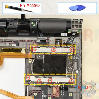

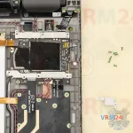
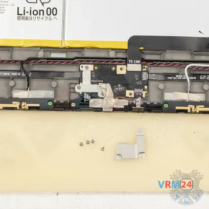
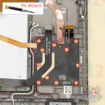
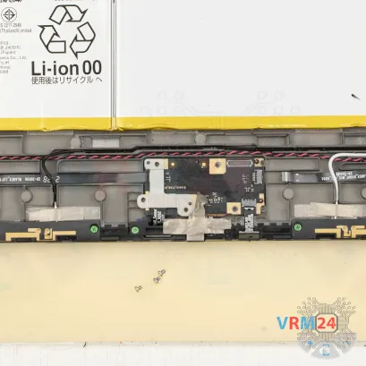
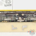
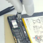
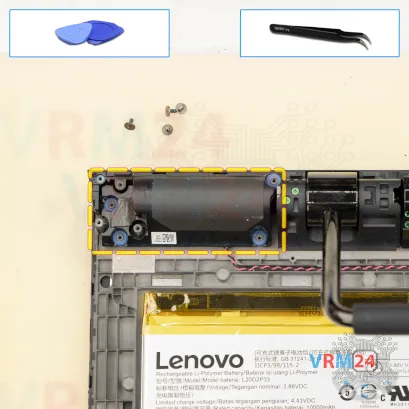
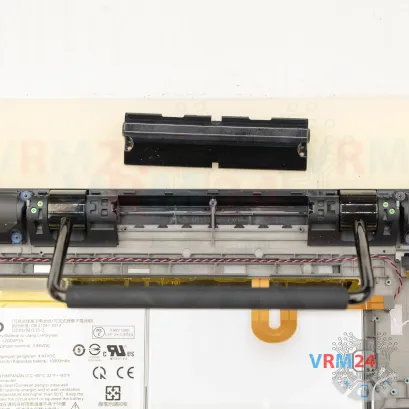
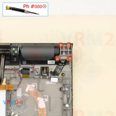
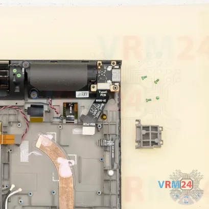
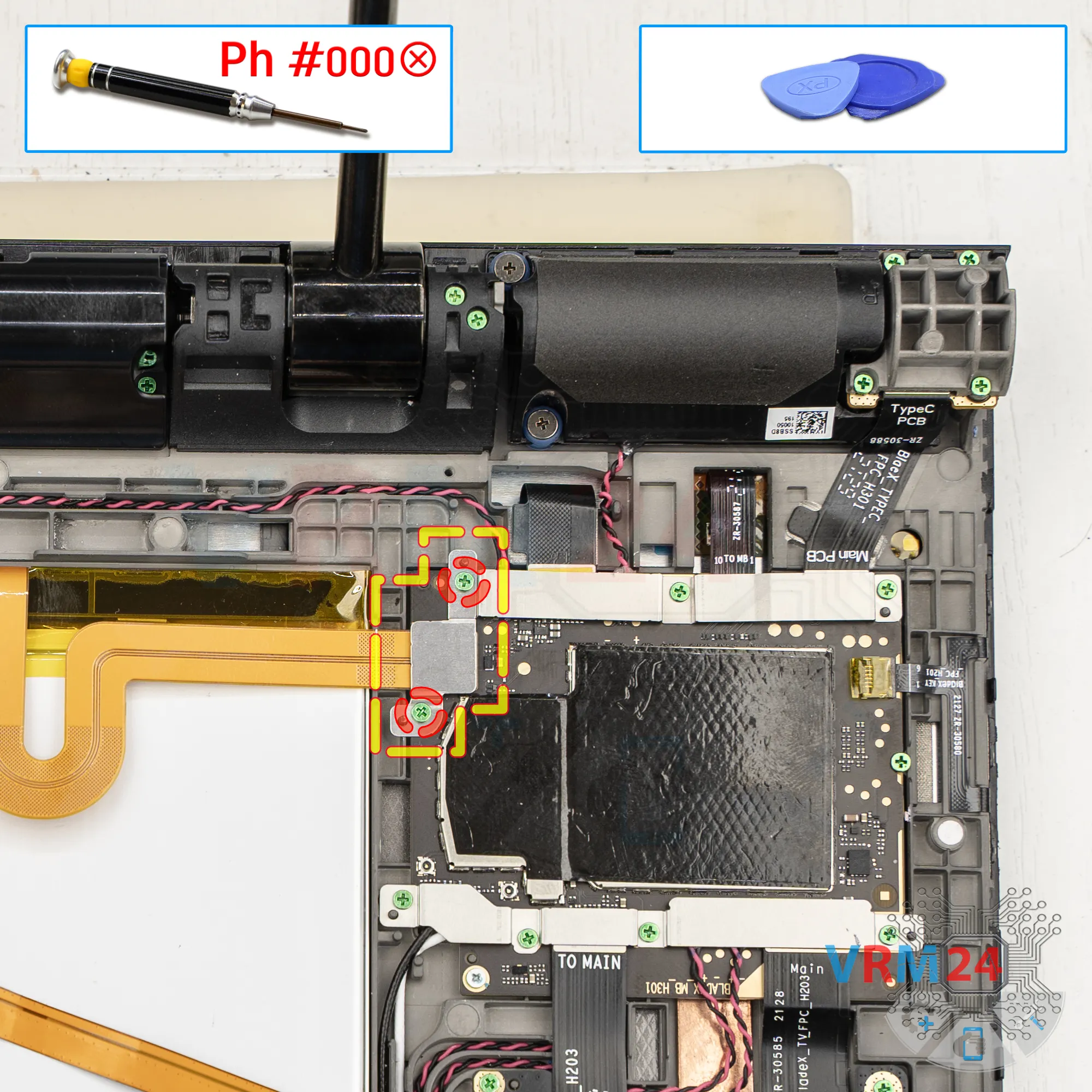
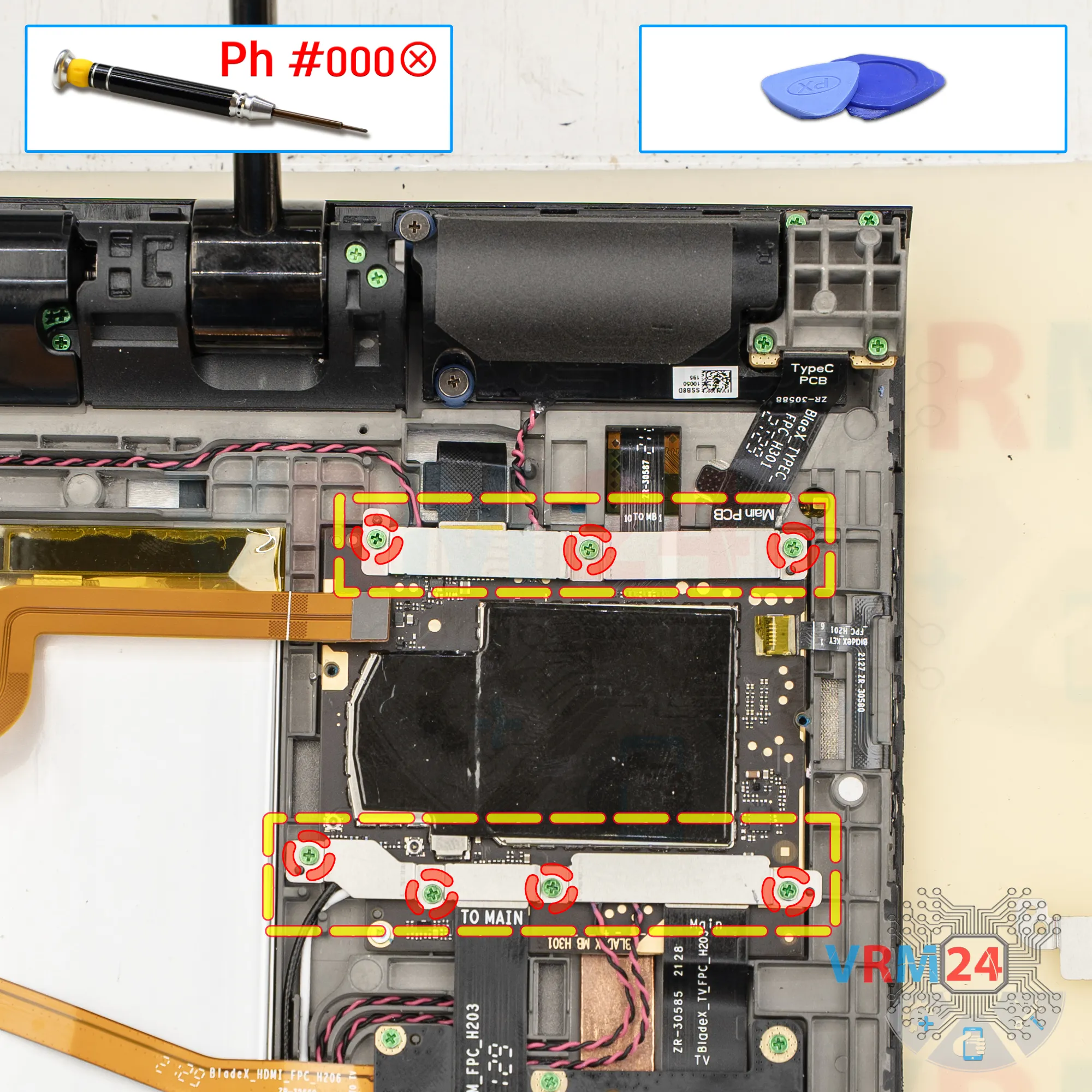
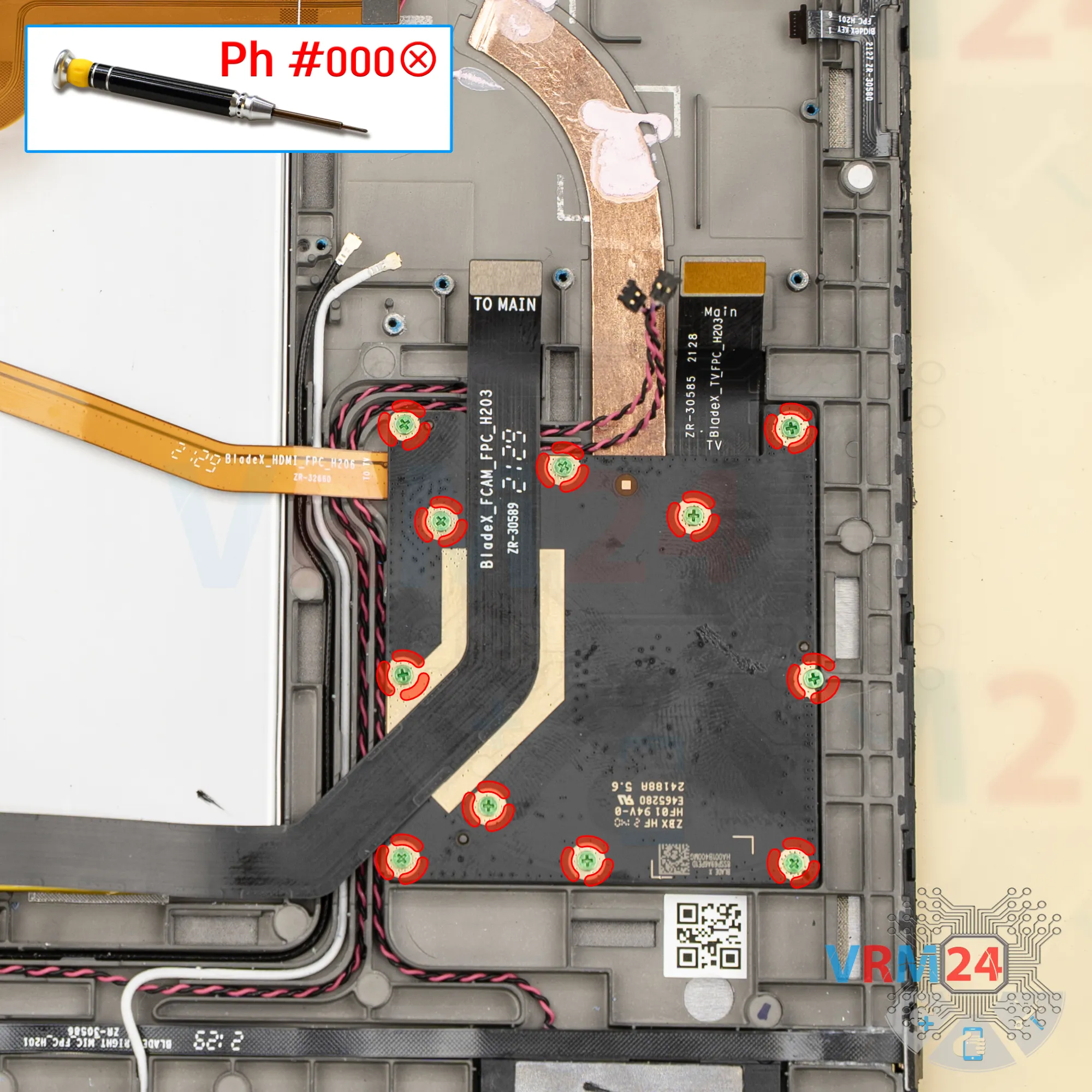
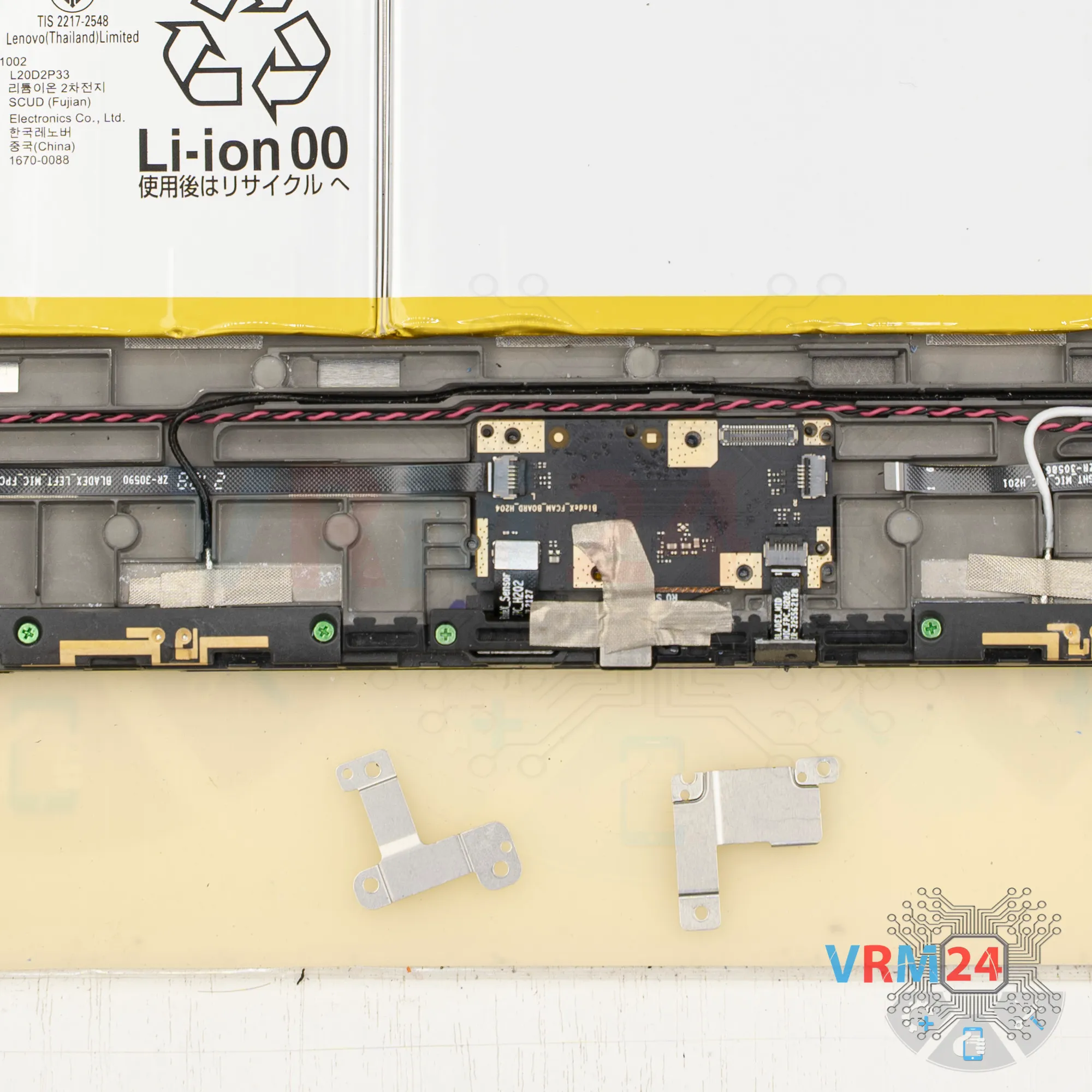
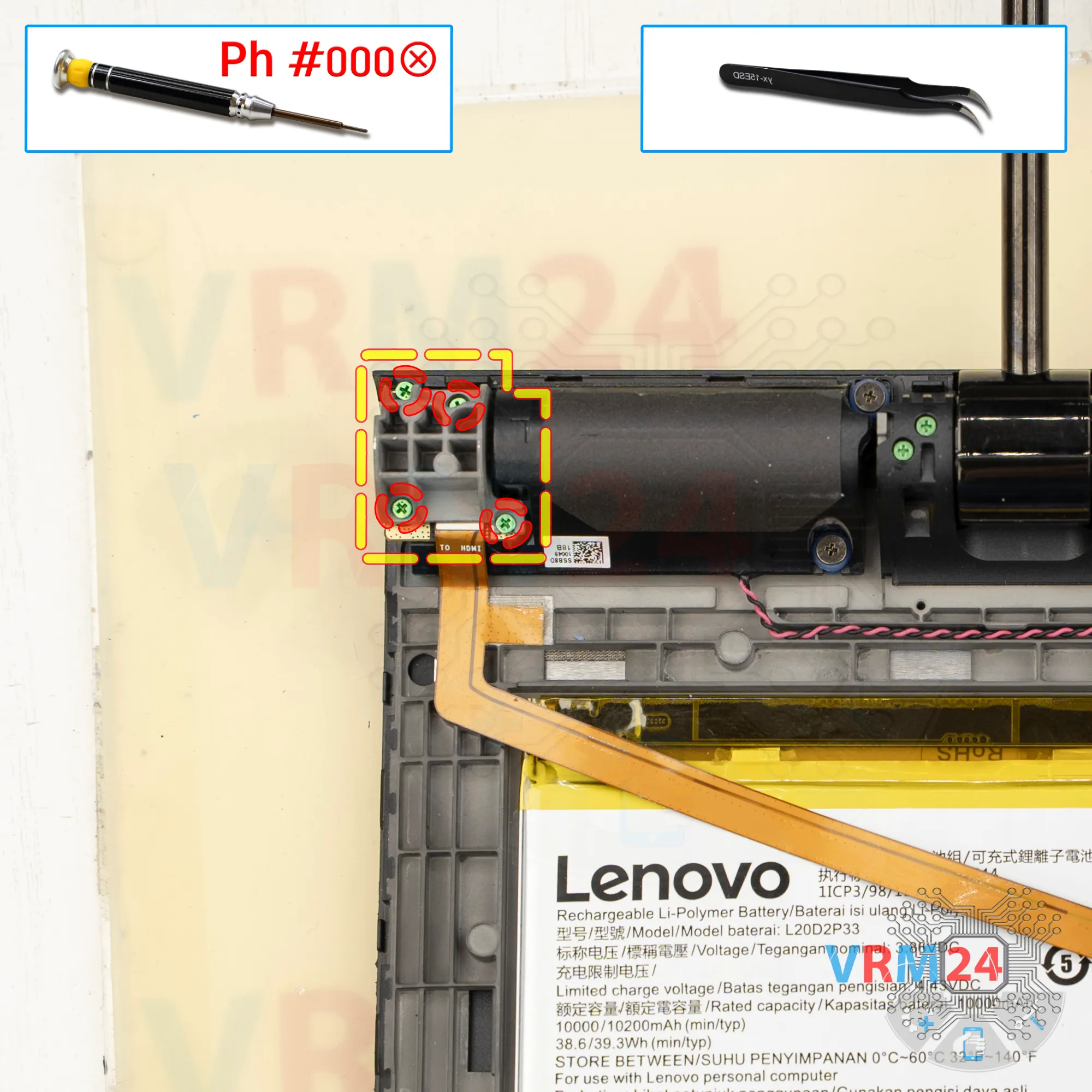
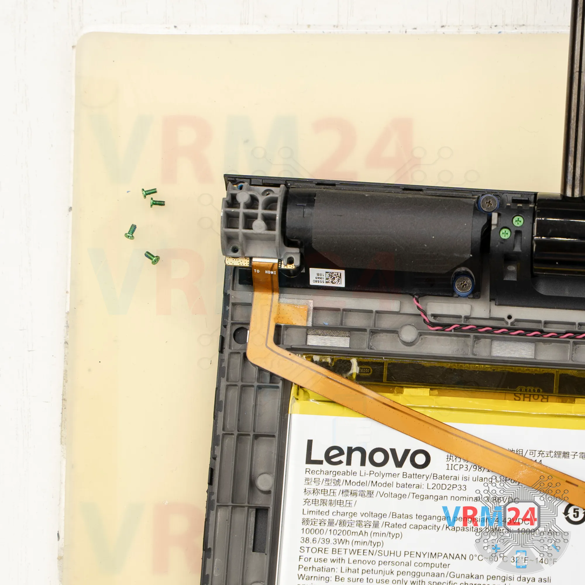
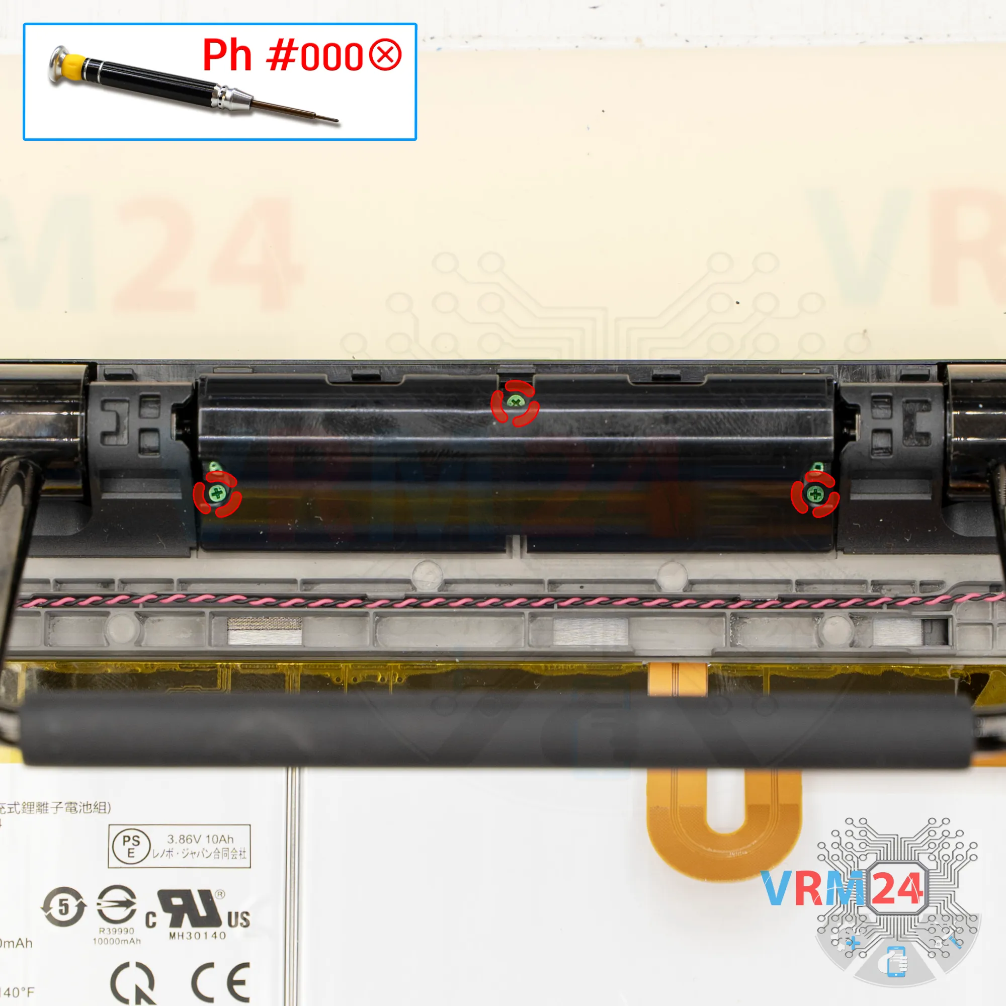
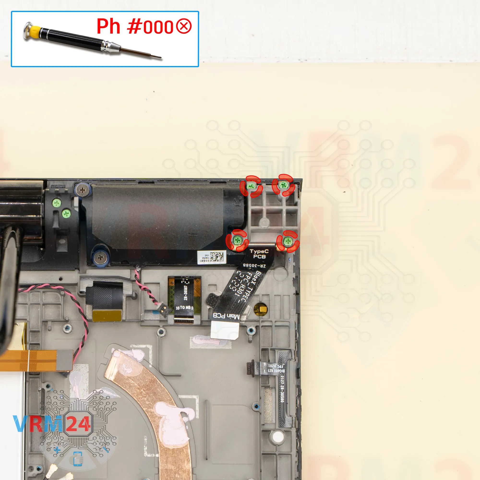
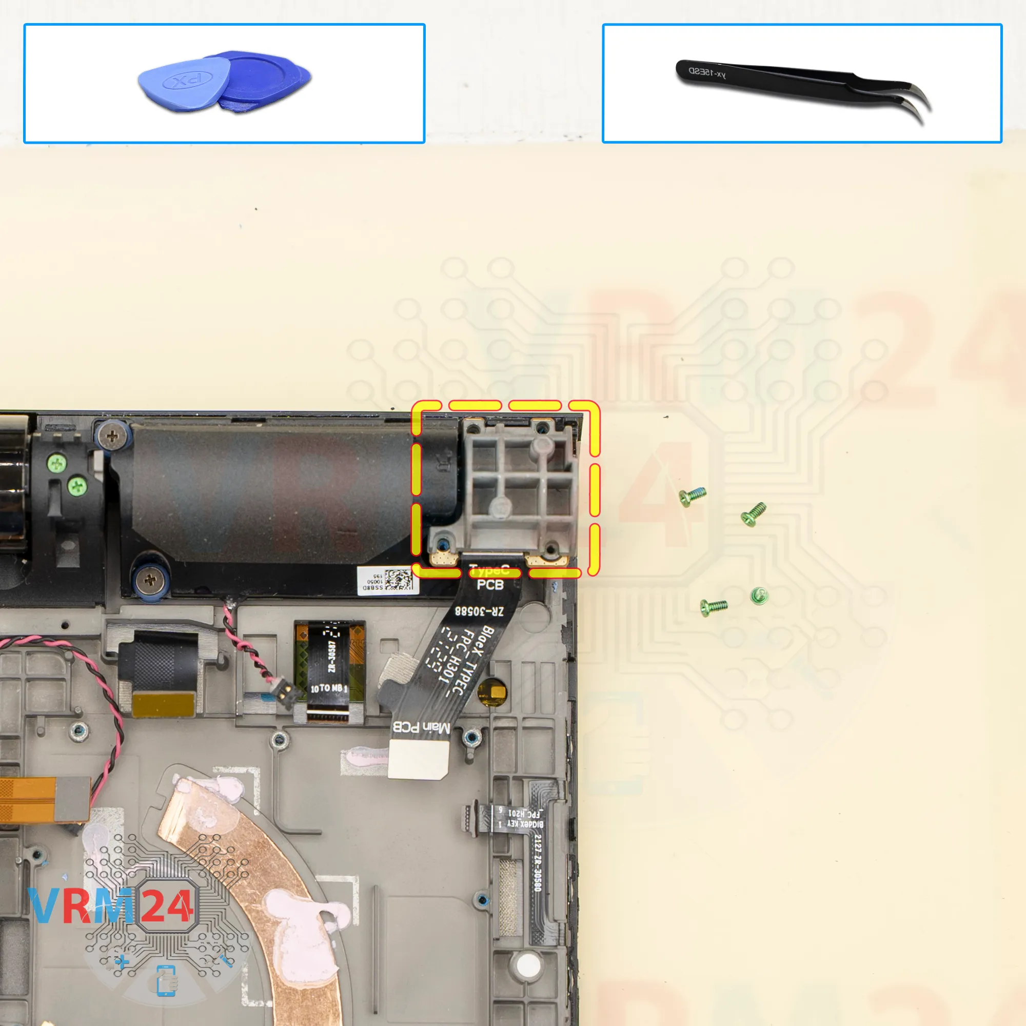
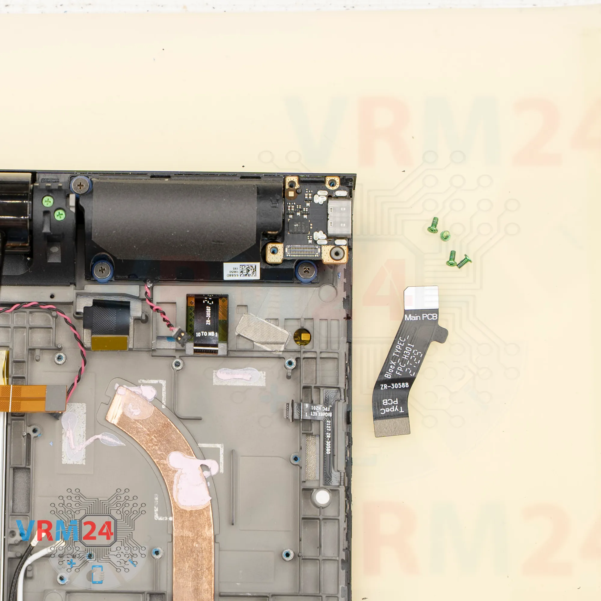
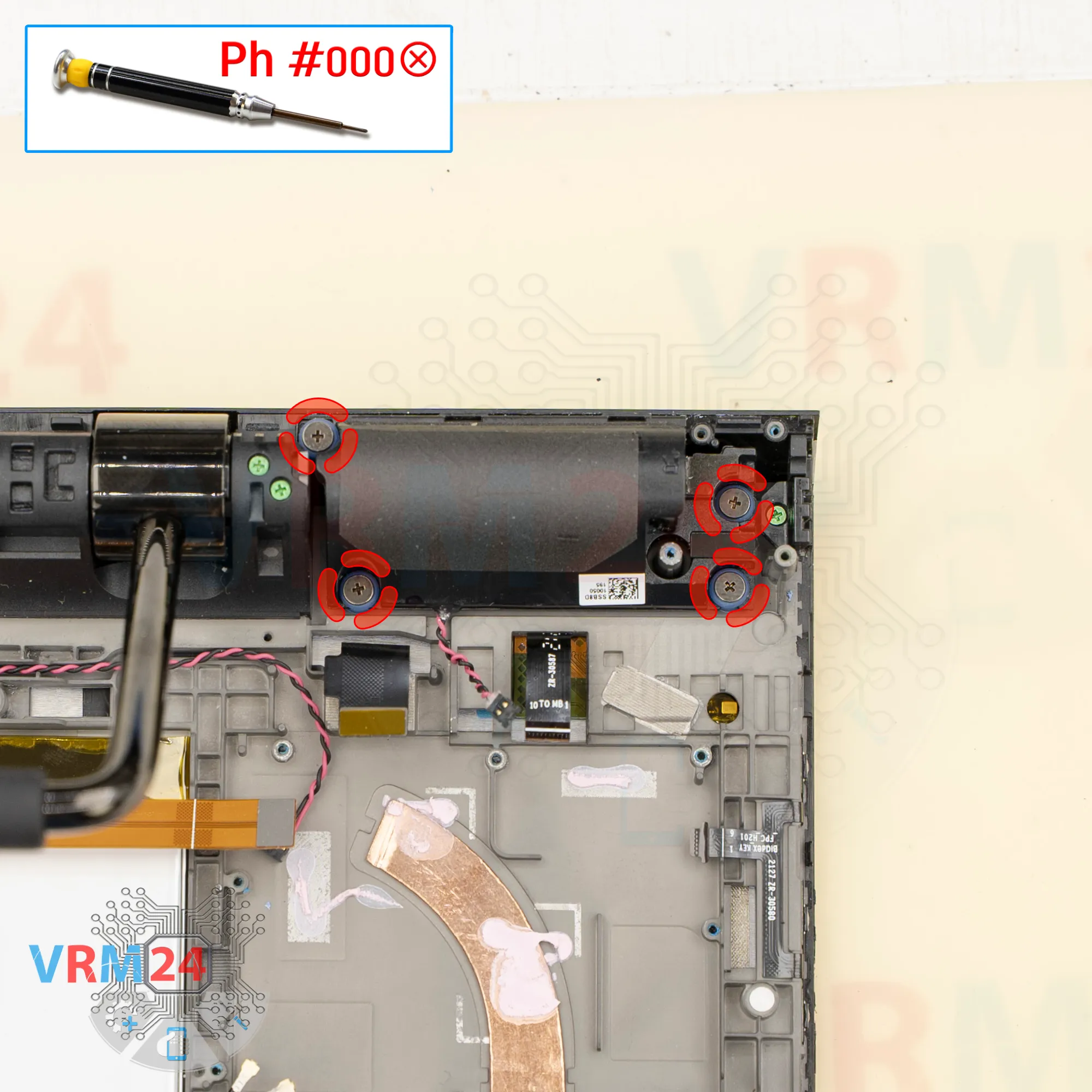
Step 5. Unscrew the screws
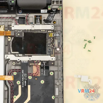
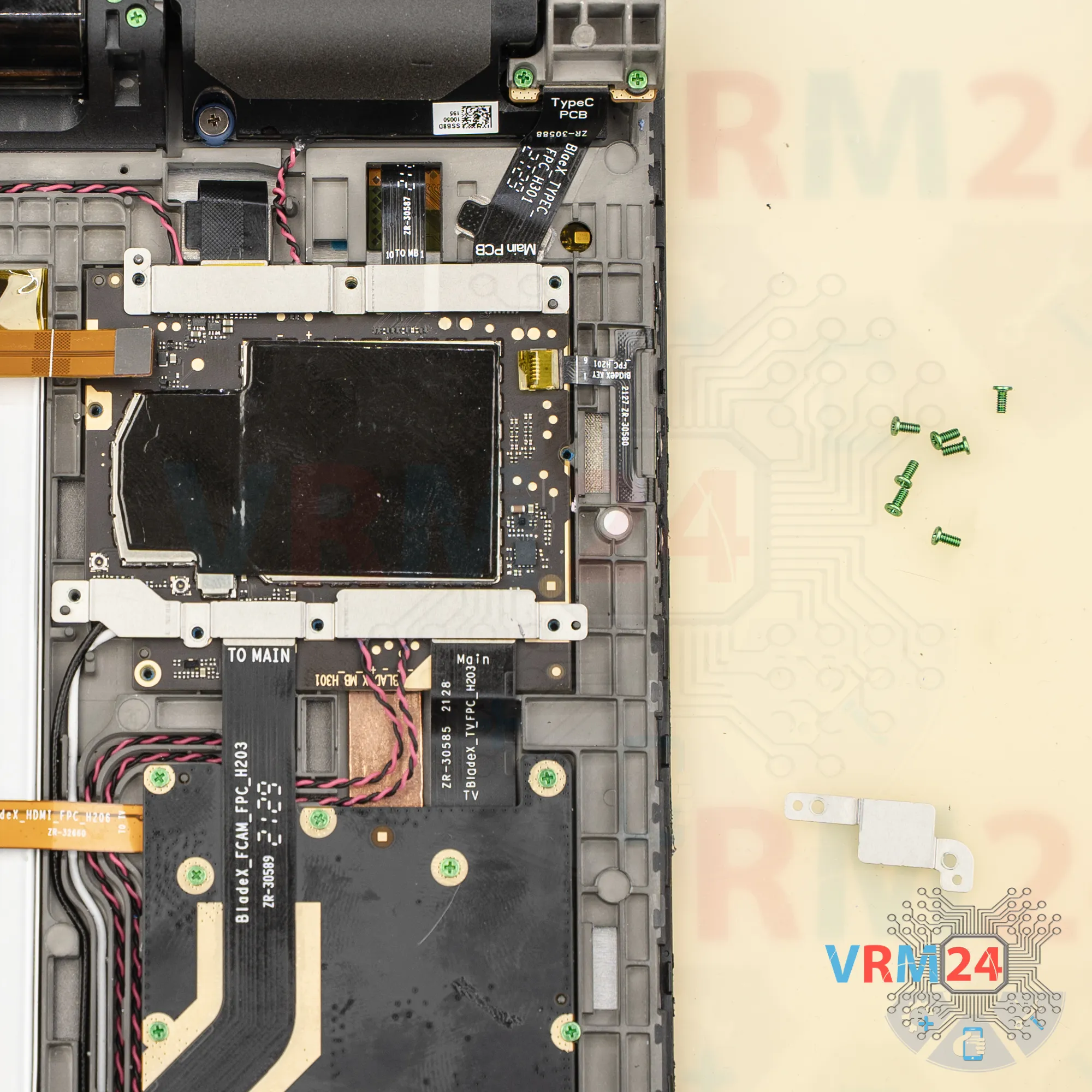
We use a 1.5 mm Phillips screwdriver, or a Phillips #000 to unscrew the screws that hold the main PCB in place.
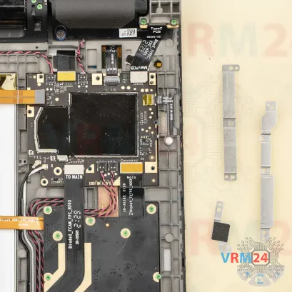
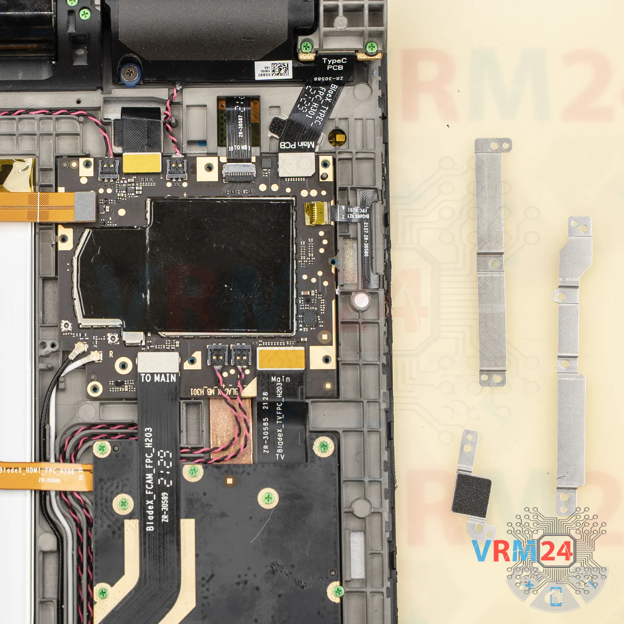
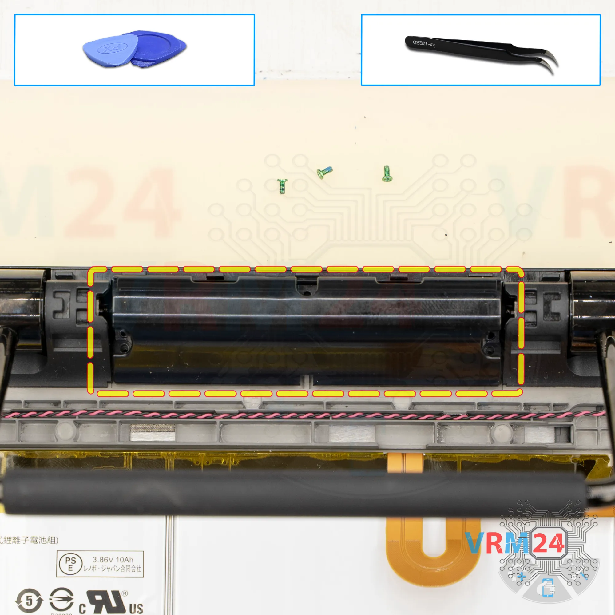
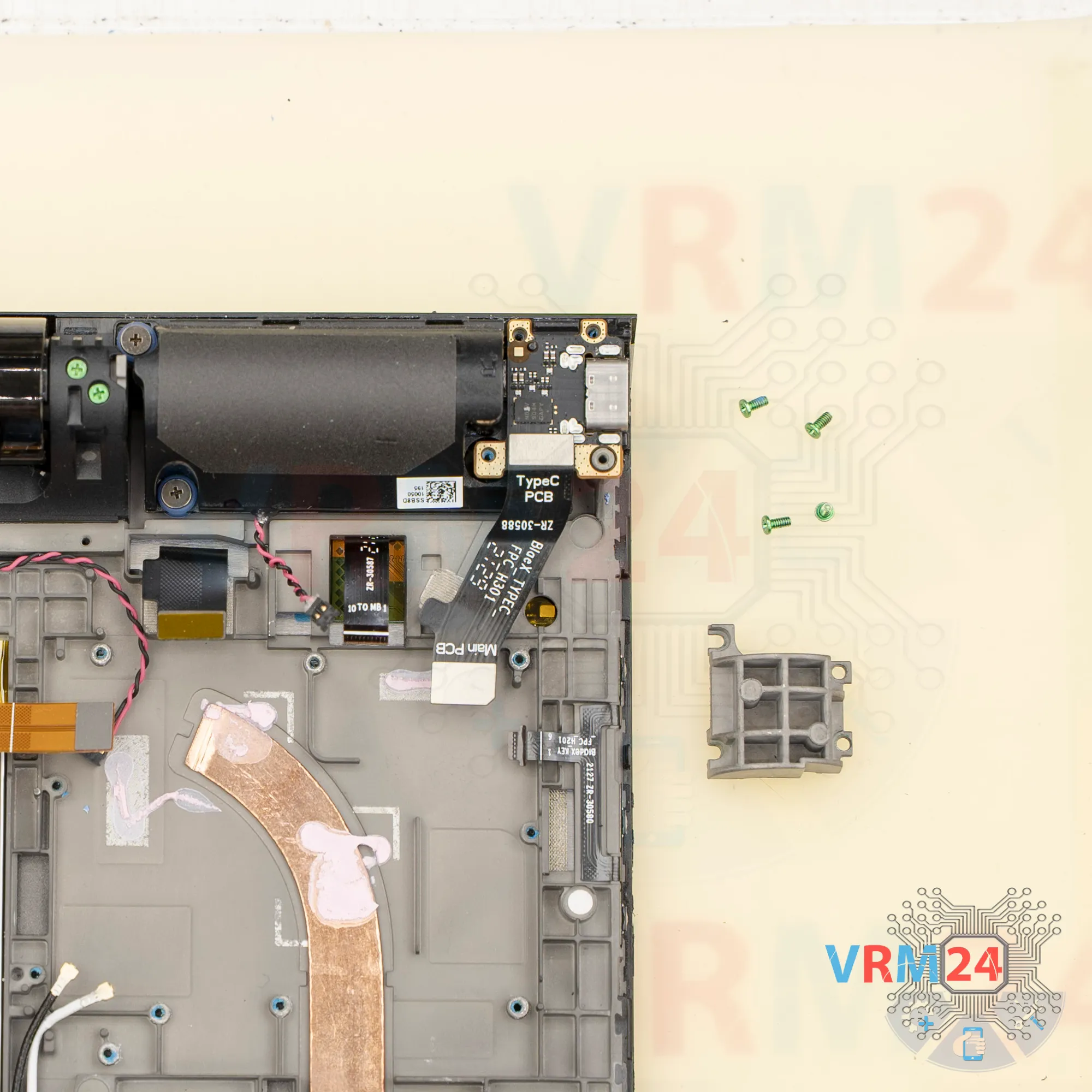
Remove the brackets and set them aside.


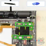

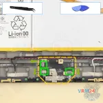
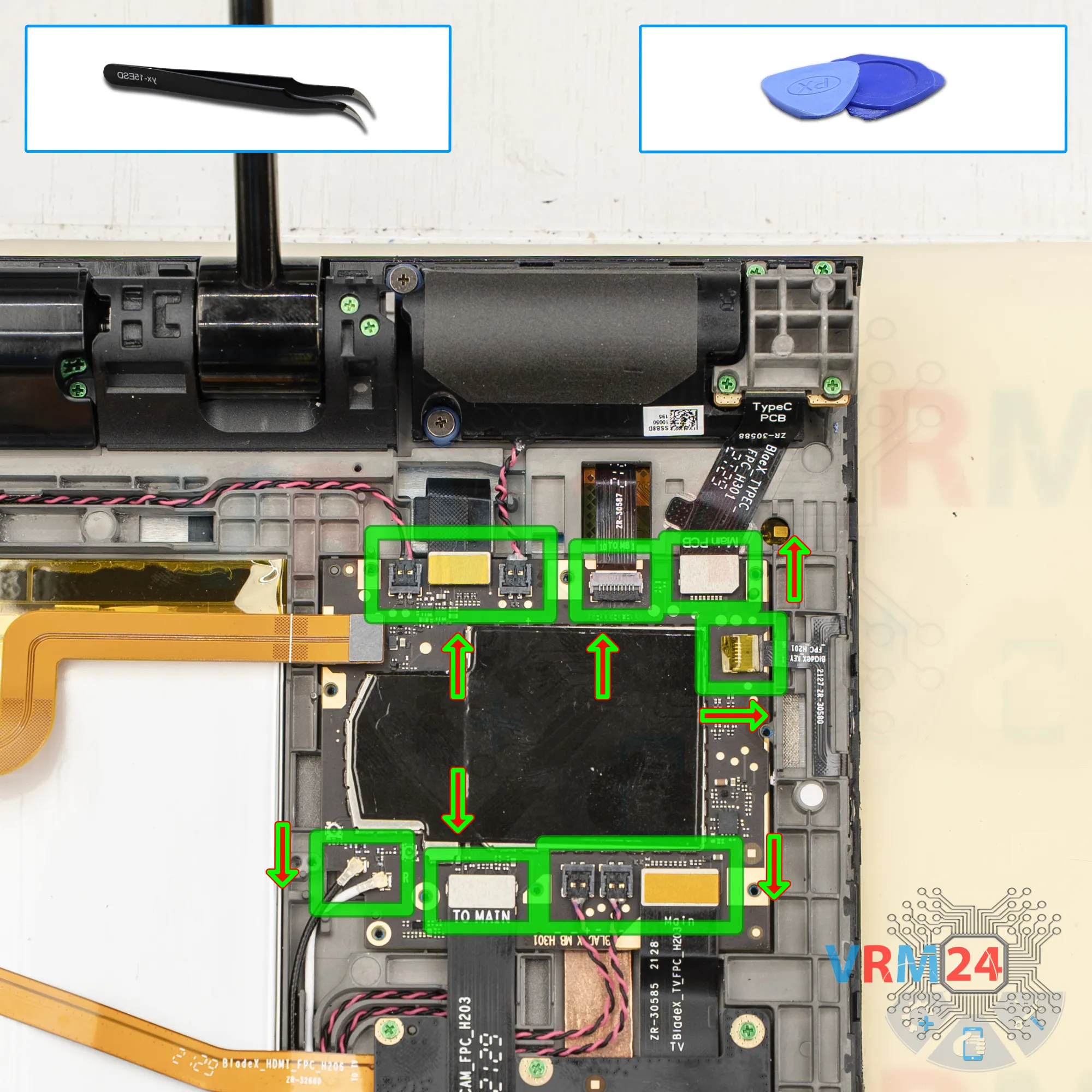
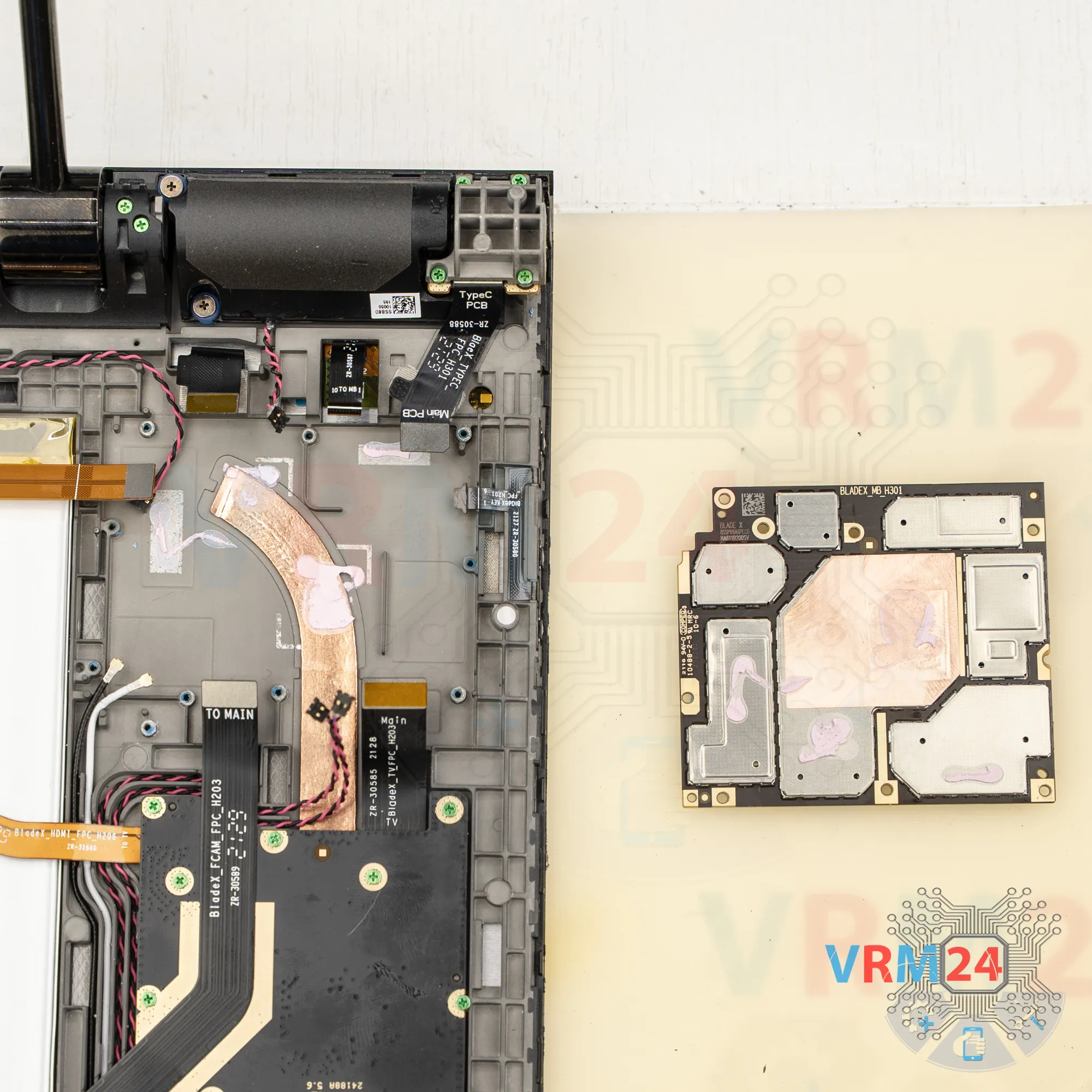
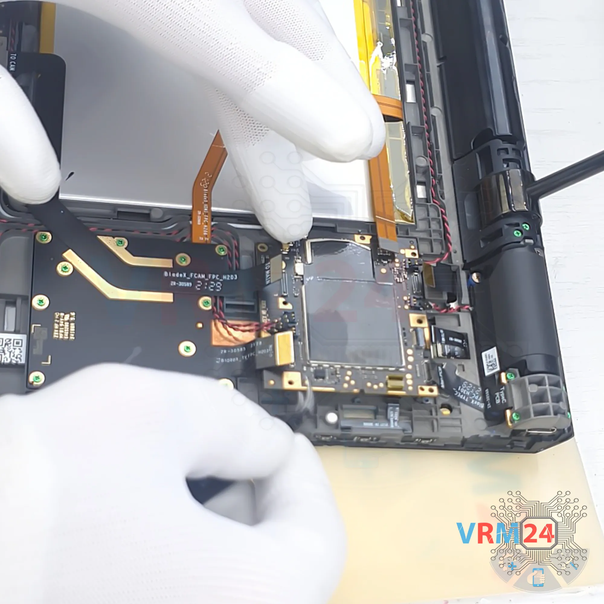
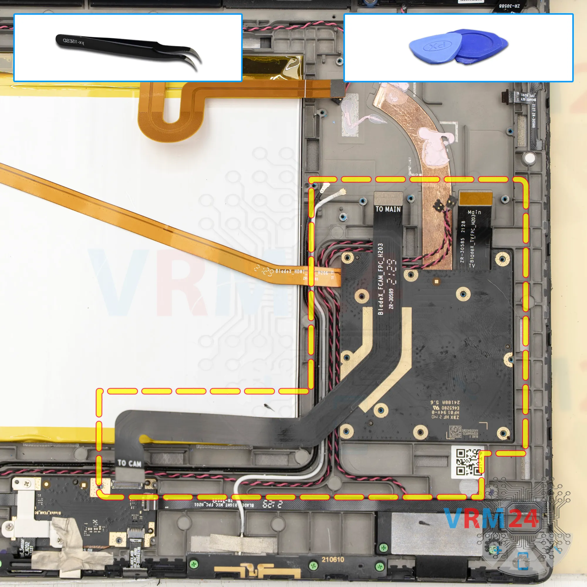
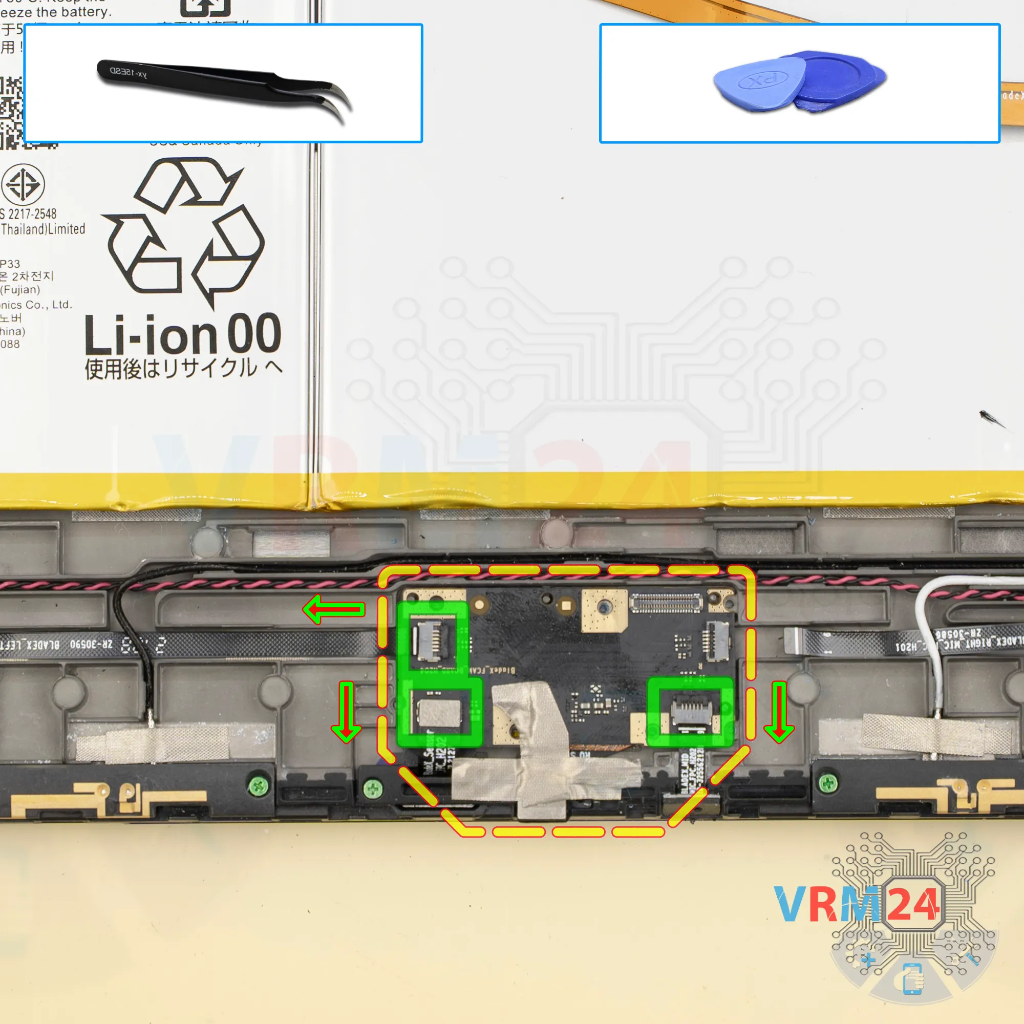
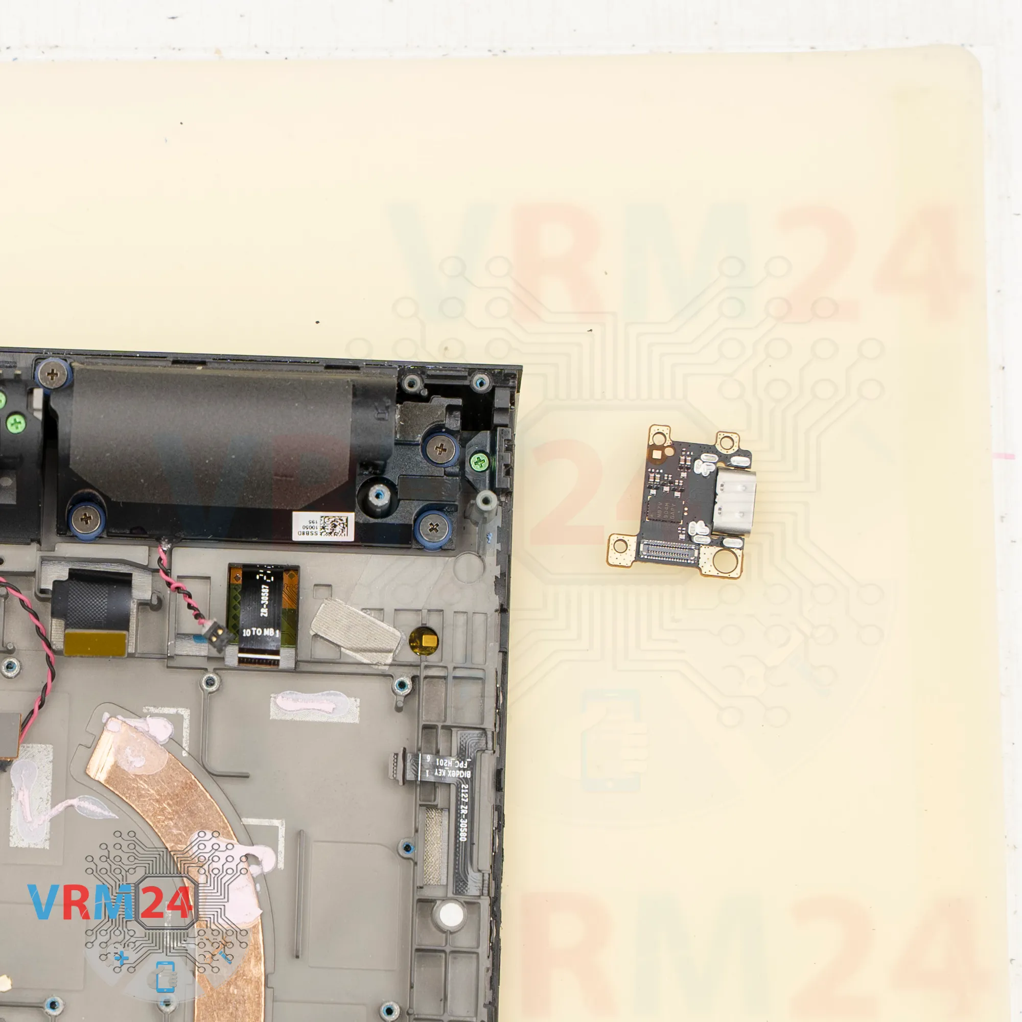
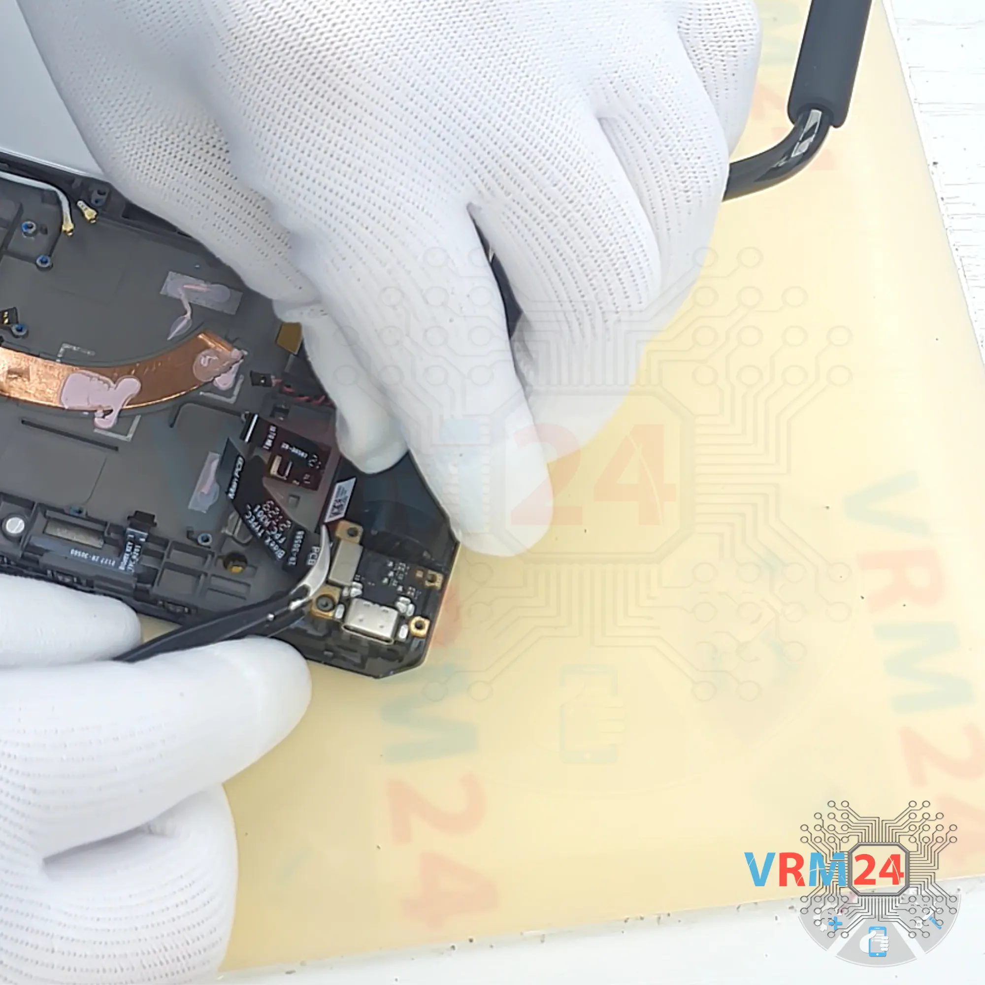
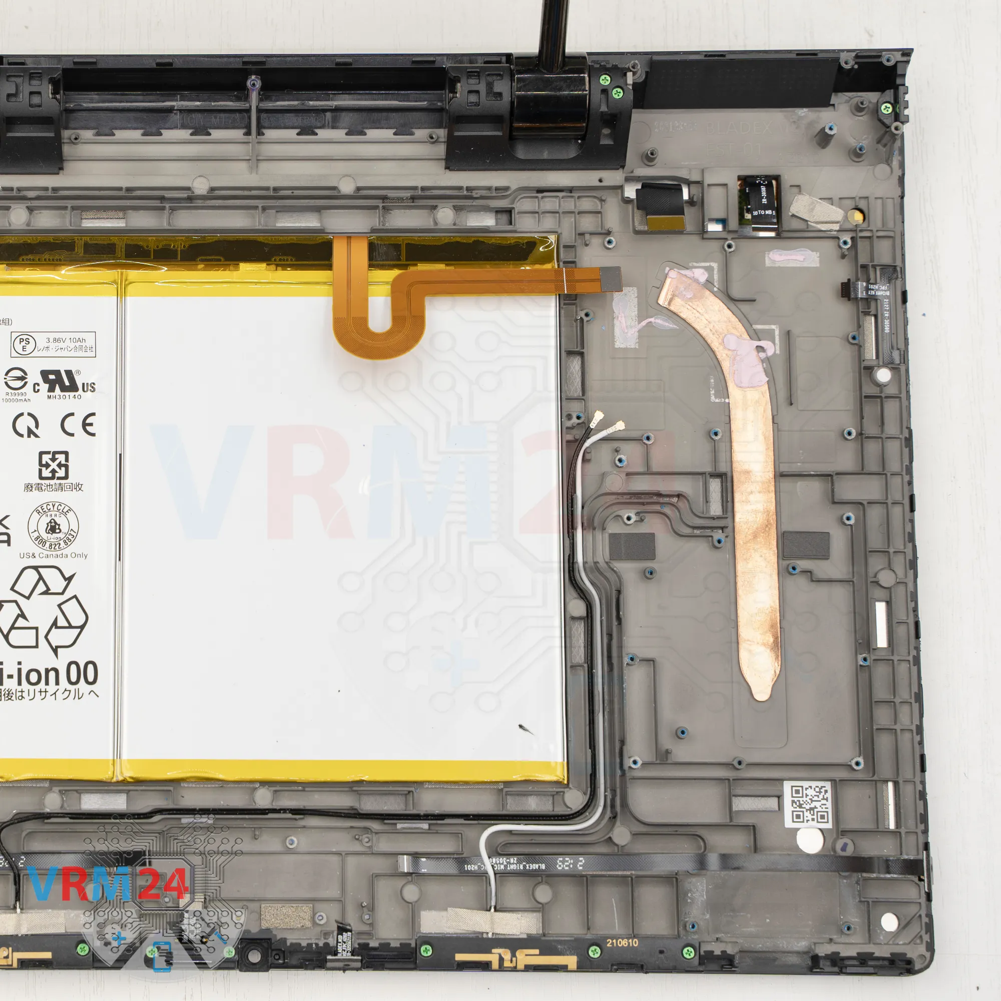
Step 6. Disconnect the connectors
Next, disconnect the connectors on the main circuit board.
Disconnect the flex cable for USB Type C port, to the display, inter-board cables, coaxial cables, and the speaker connectors.
The coaxial connectors are very hard to disconnect, so be careful.
Also, make sure there are no microchips near the area where you’re pressing, so you don’t accidentally damage them.
And we can remove the motherboard.

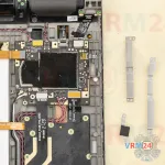
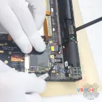
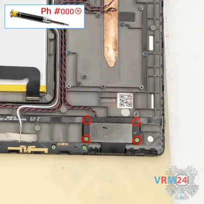
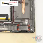
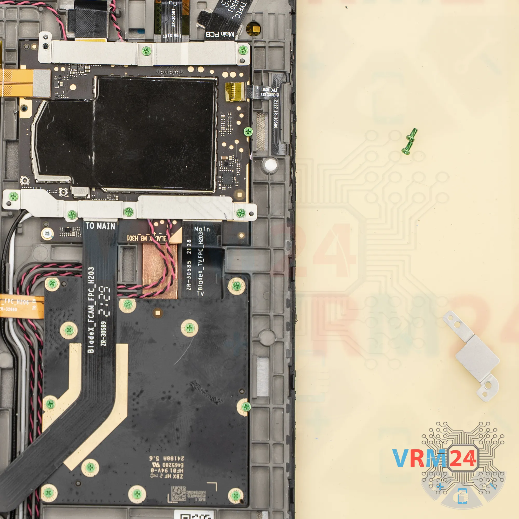
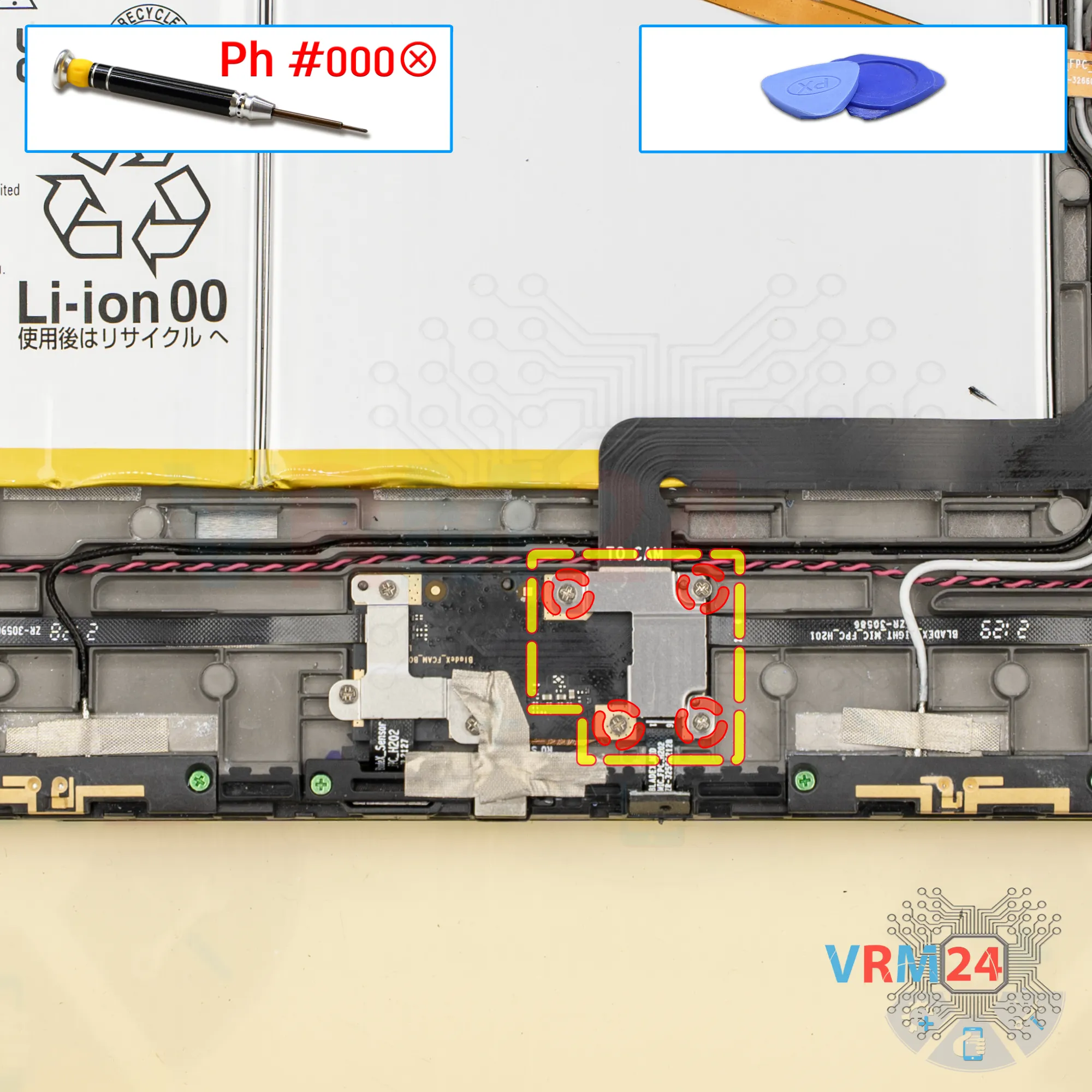
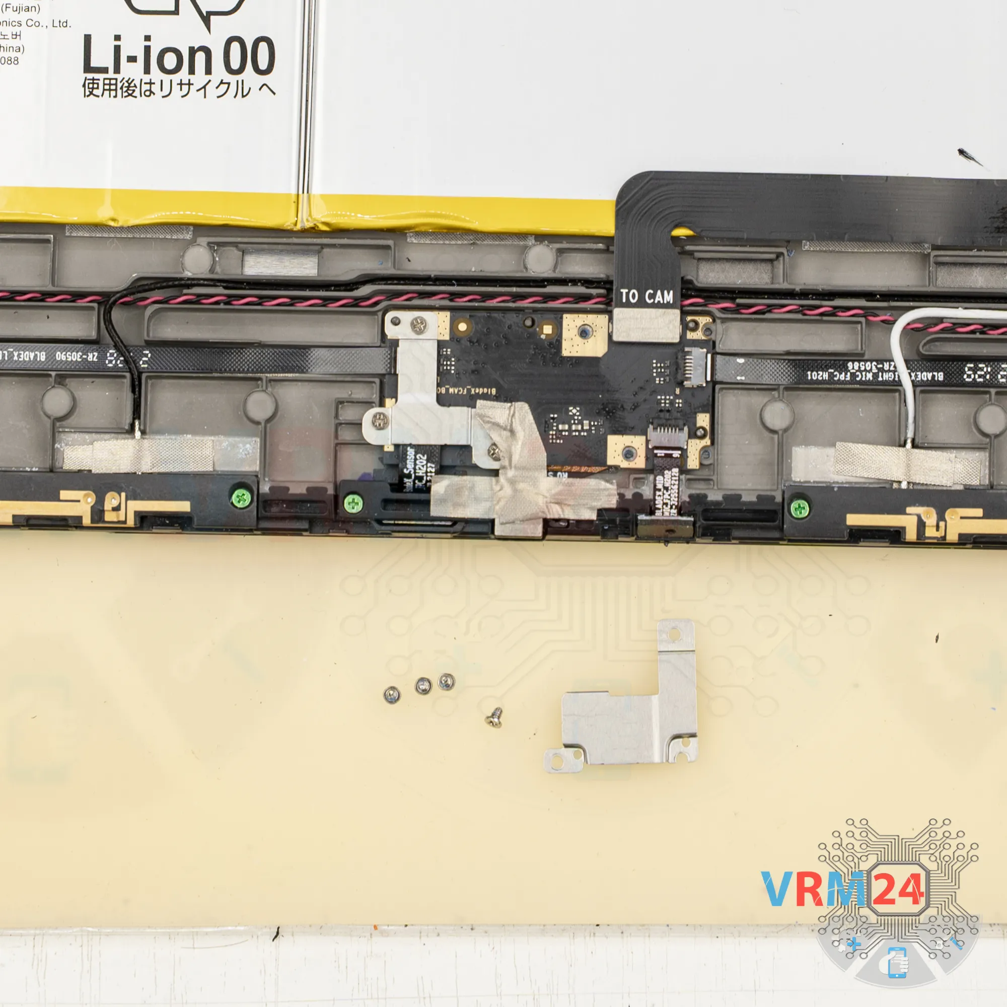
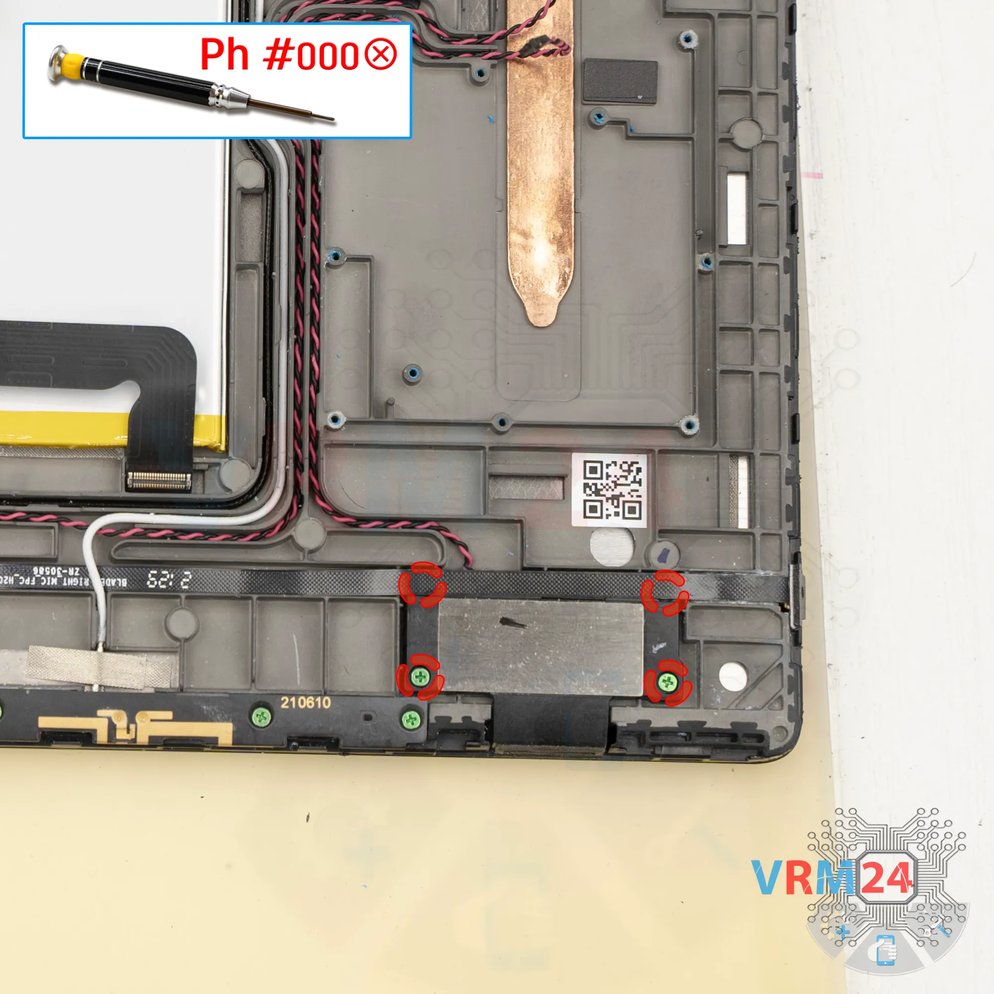
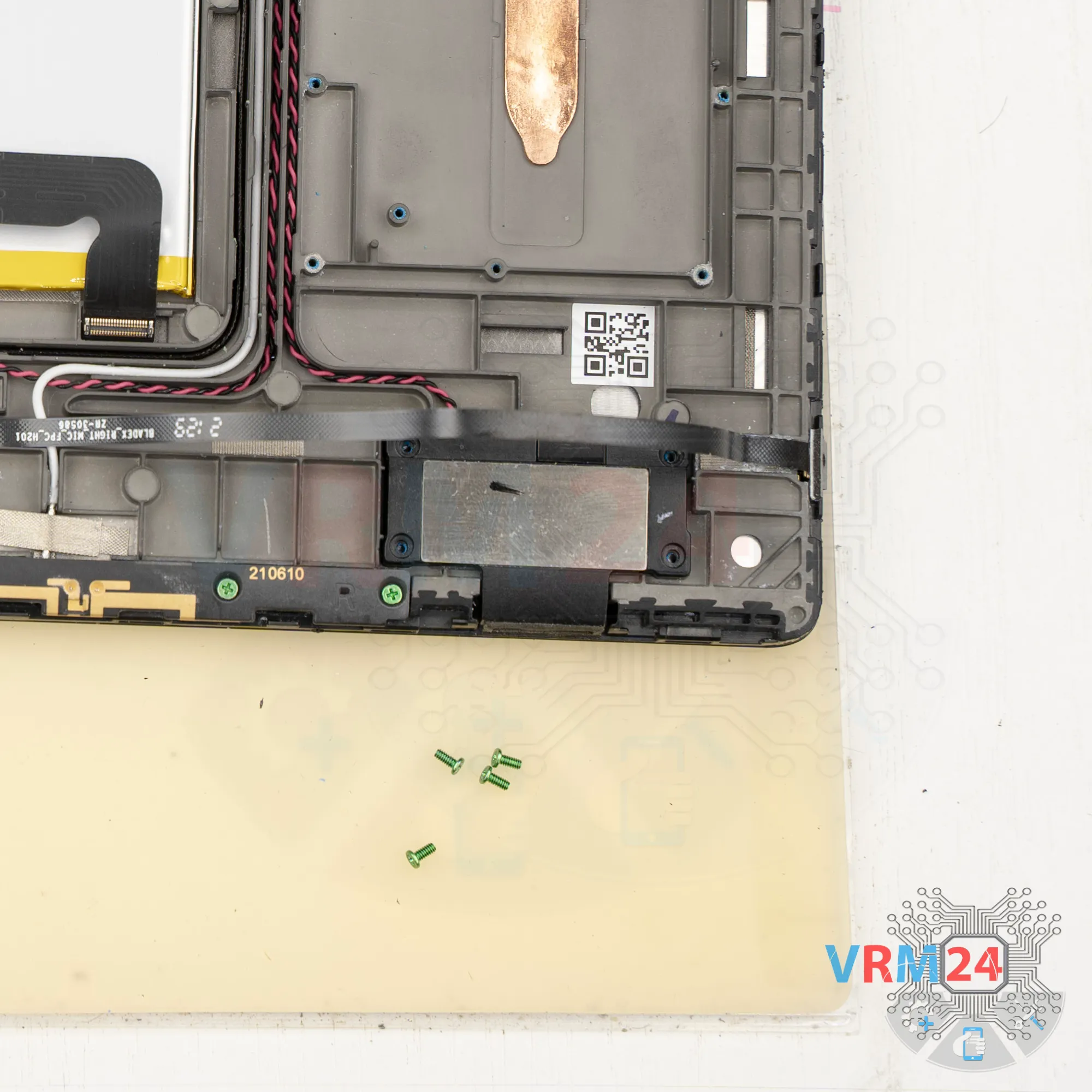
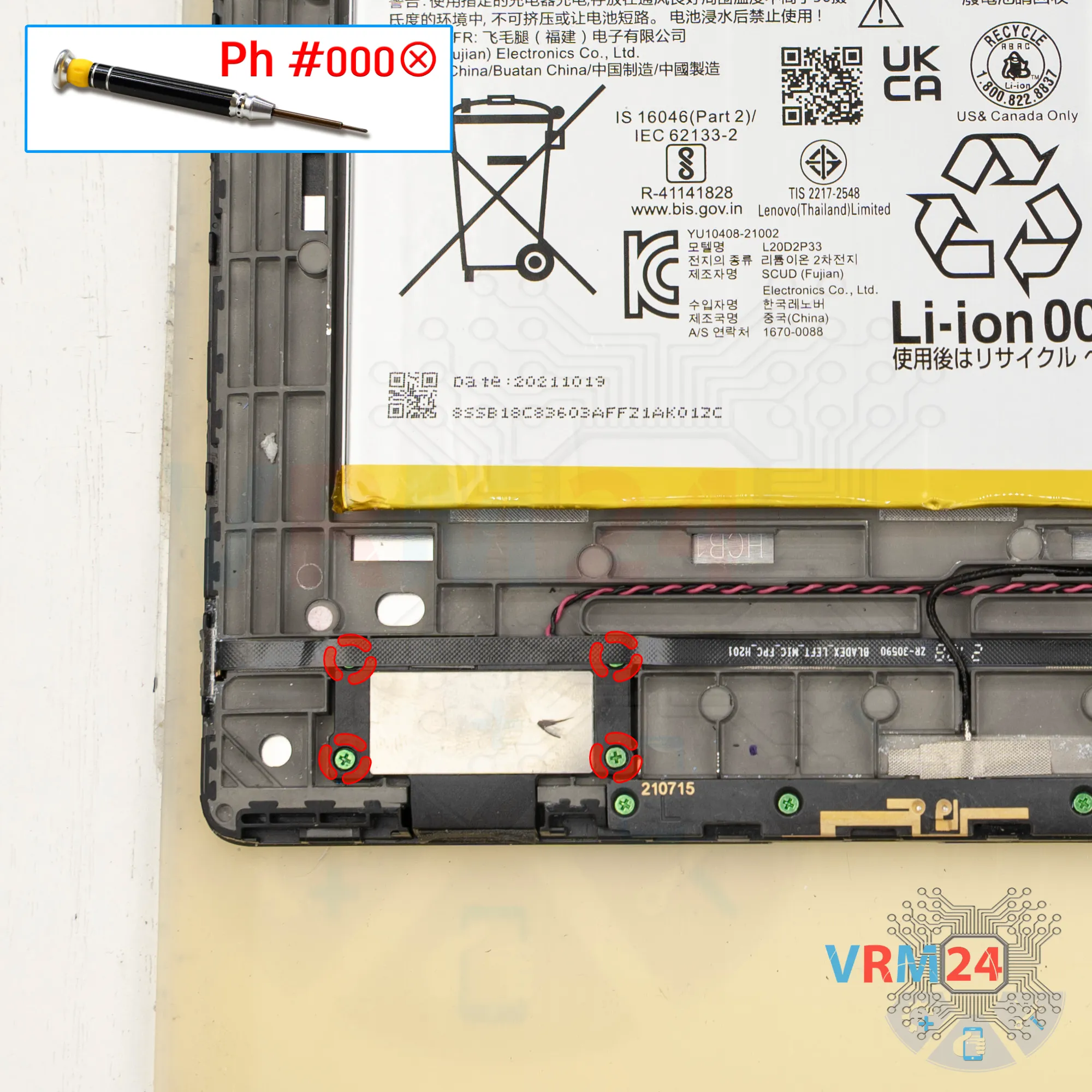
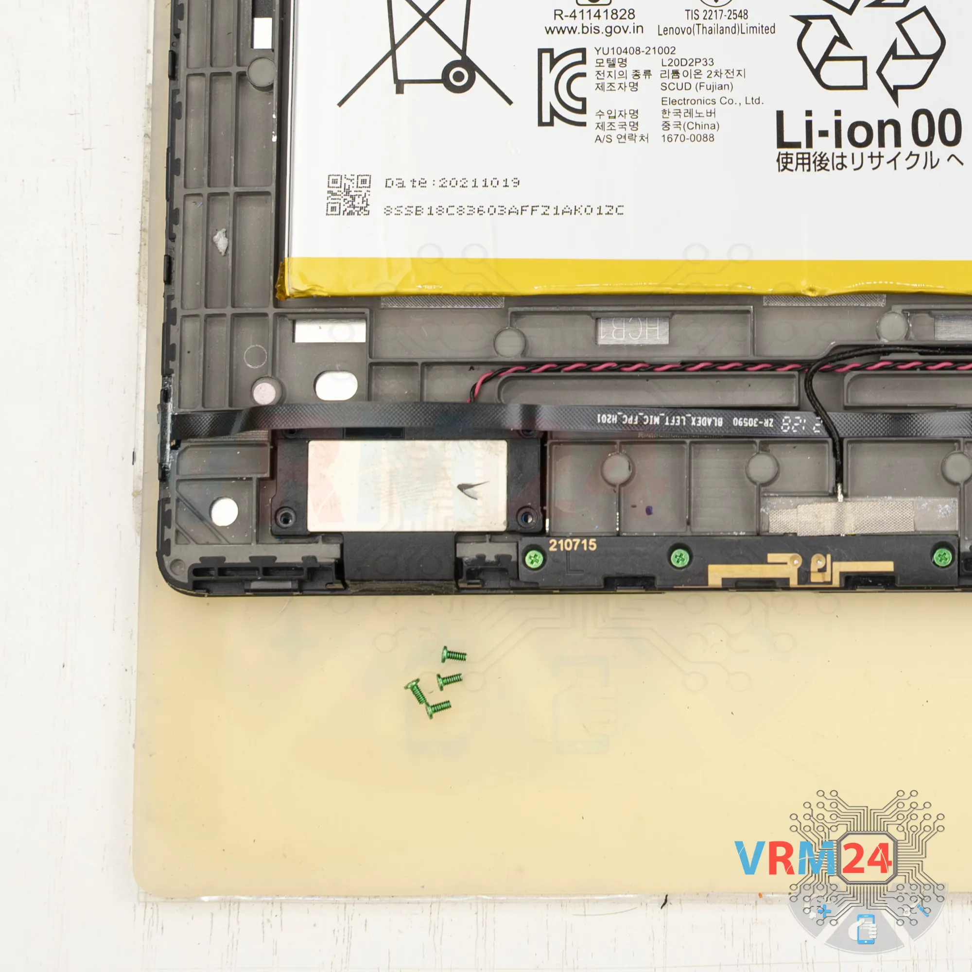
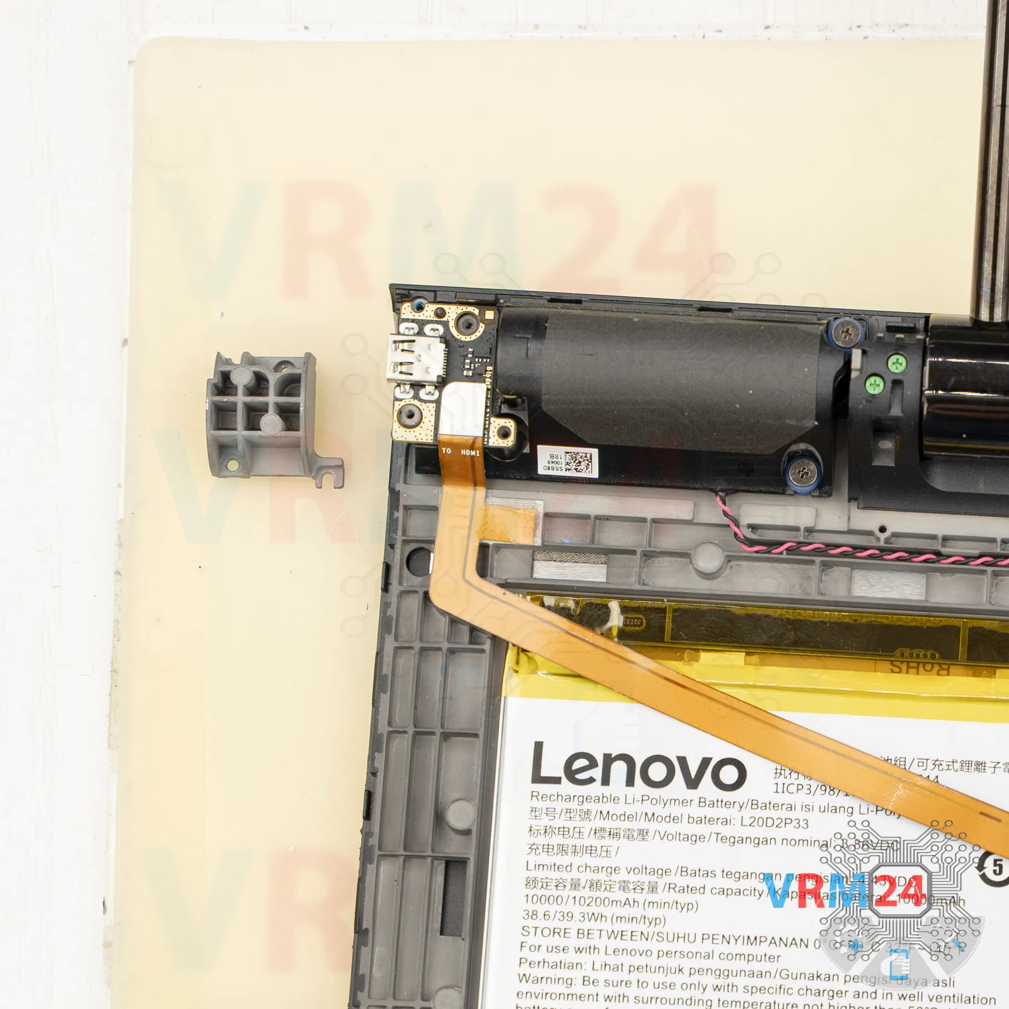
Step 7. Unscrew the screws
After that, unscrew the four screws at the bottom that hold the inter-board flex cables and the microphone flex cable.
Remove the bracket.

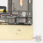
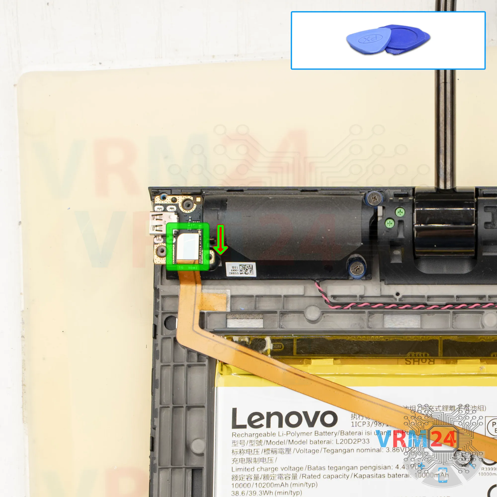
Step 8. Disconnect the connectors
We disconnect the inter-board flex cable and the microphone flex cable.
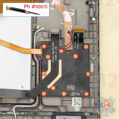

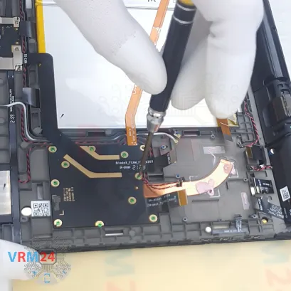
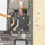

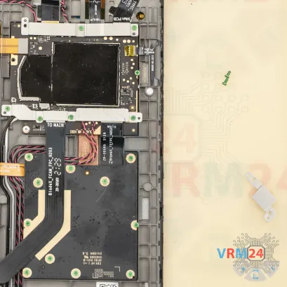
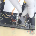
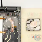
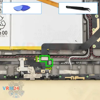
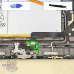
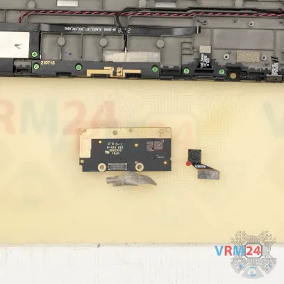
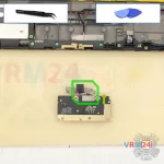
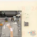
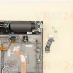
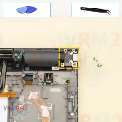
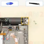
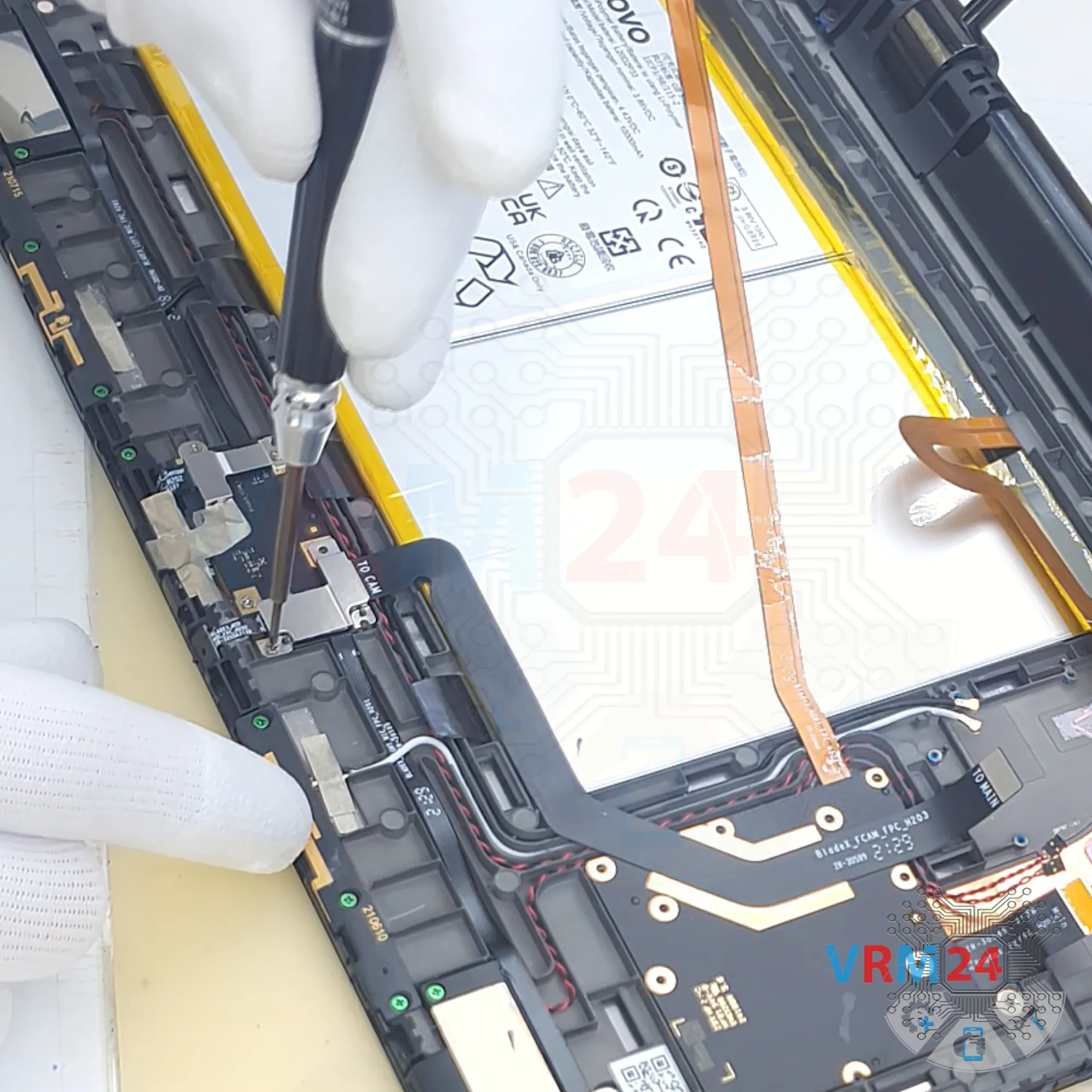
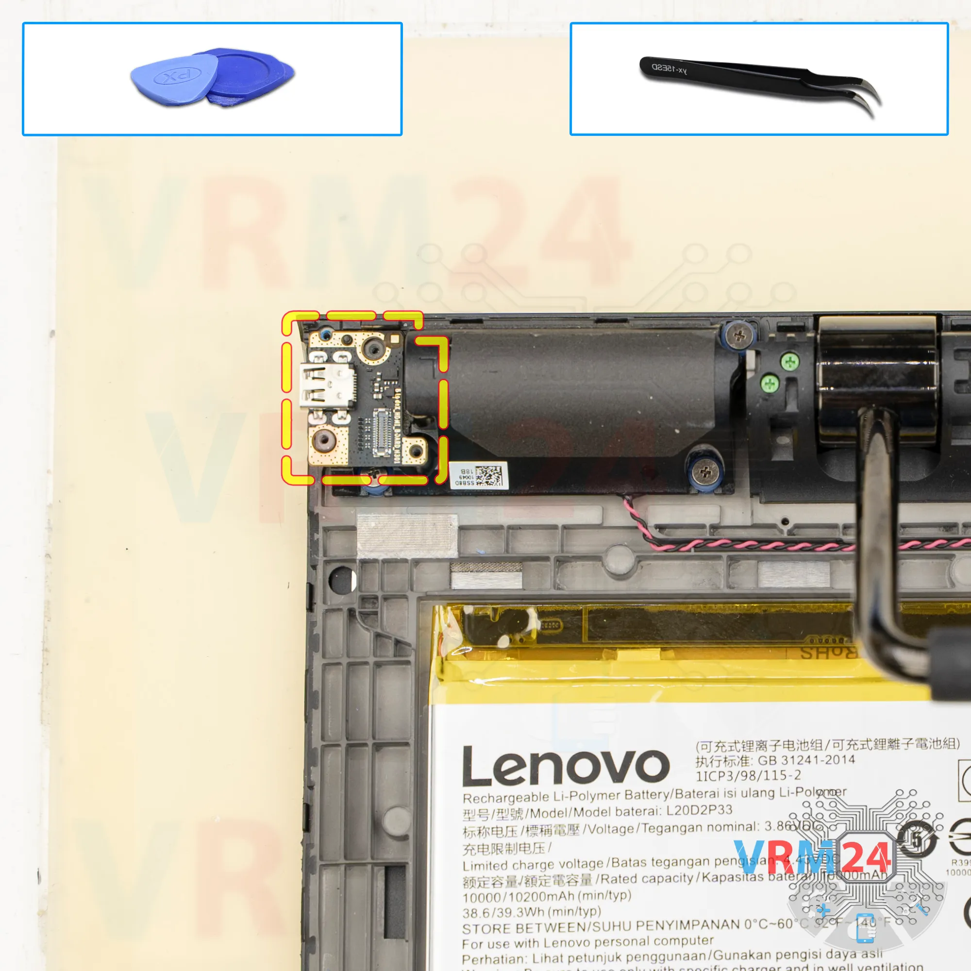
Step 9. Unscrew the screws
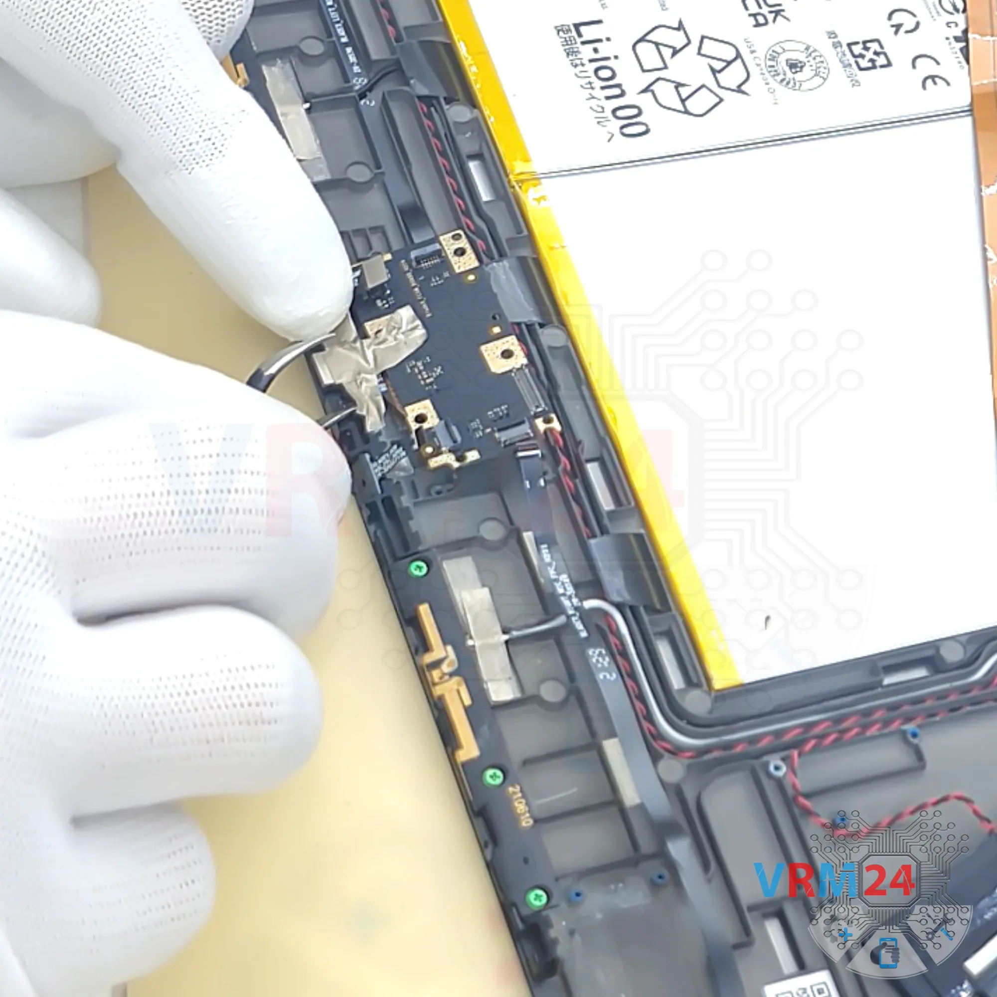
Next, we move on to unscrewing the screws on the secondary circuit board, which likely houses the video processor.
Unscrew the screws and set them aside on our organized surface.
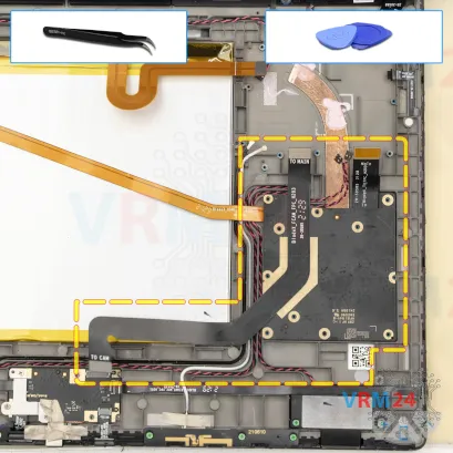
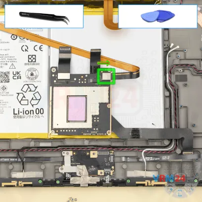


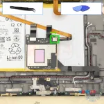
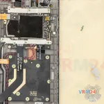
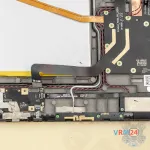
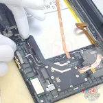
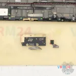
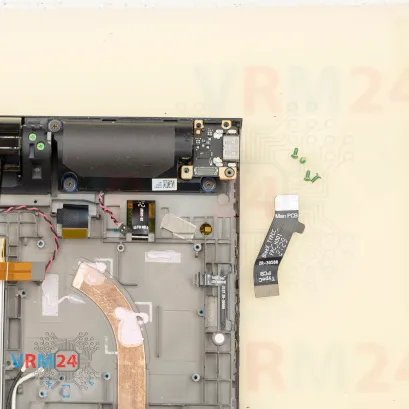
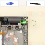
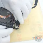
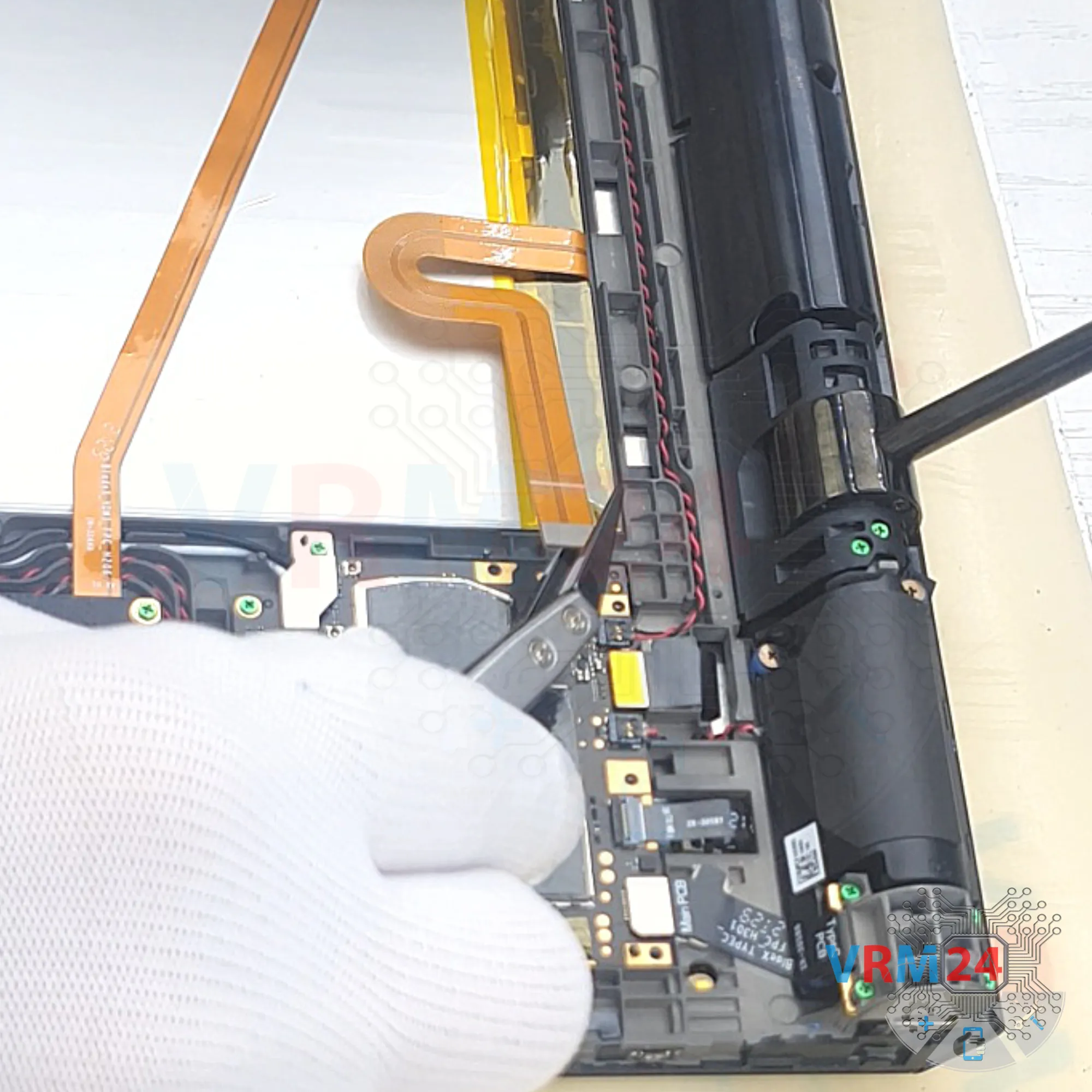
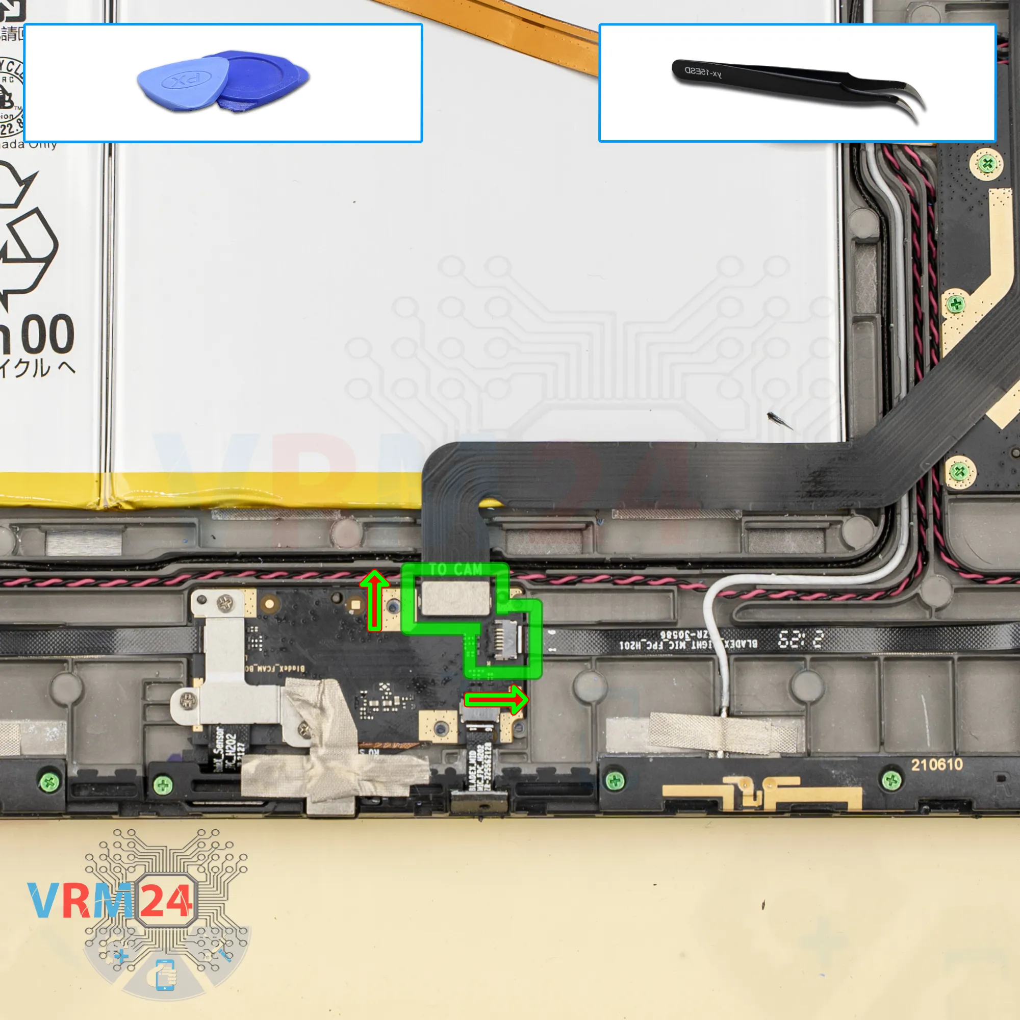
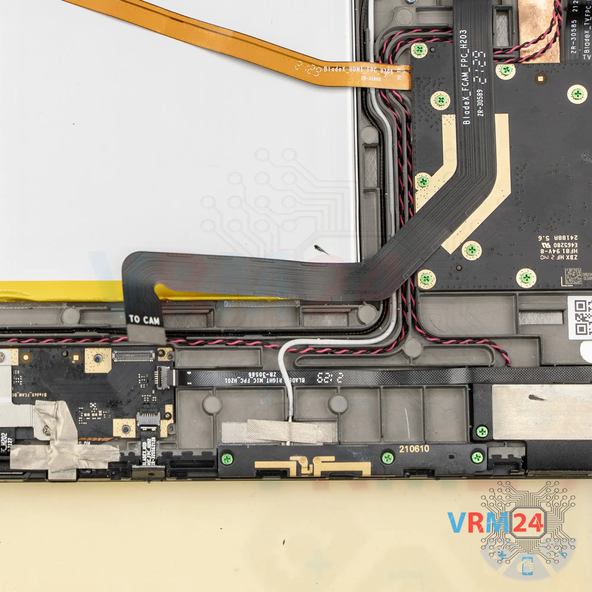
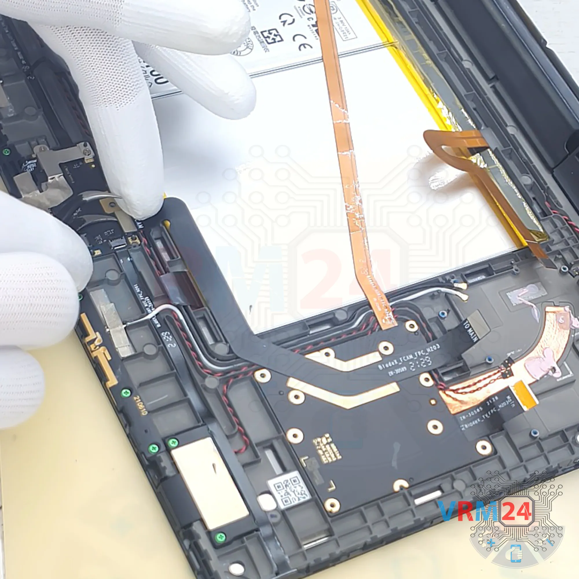
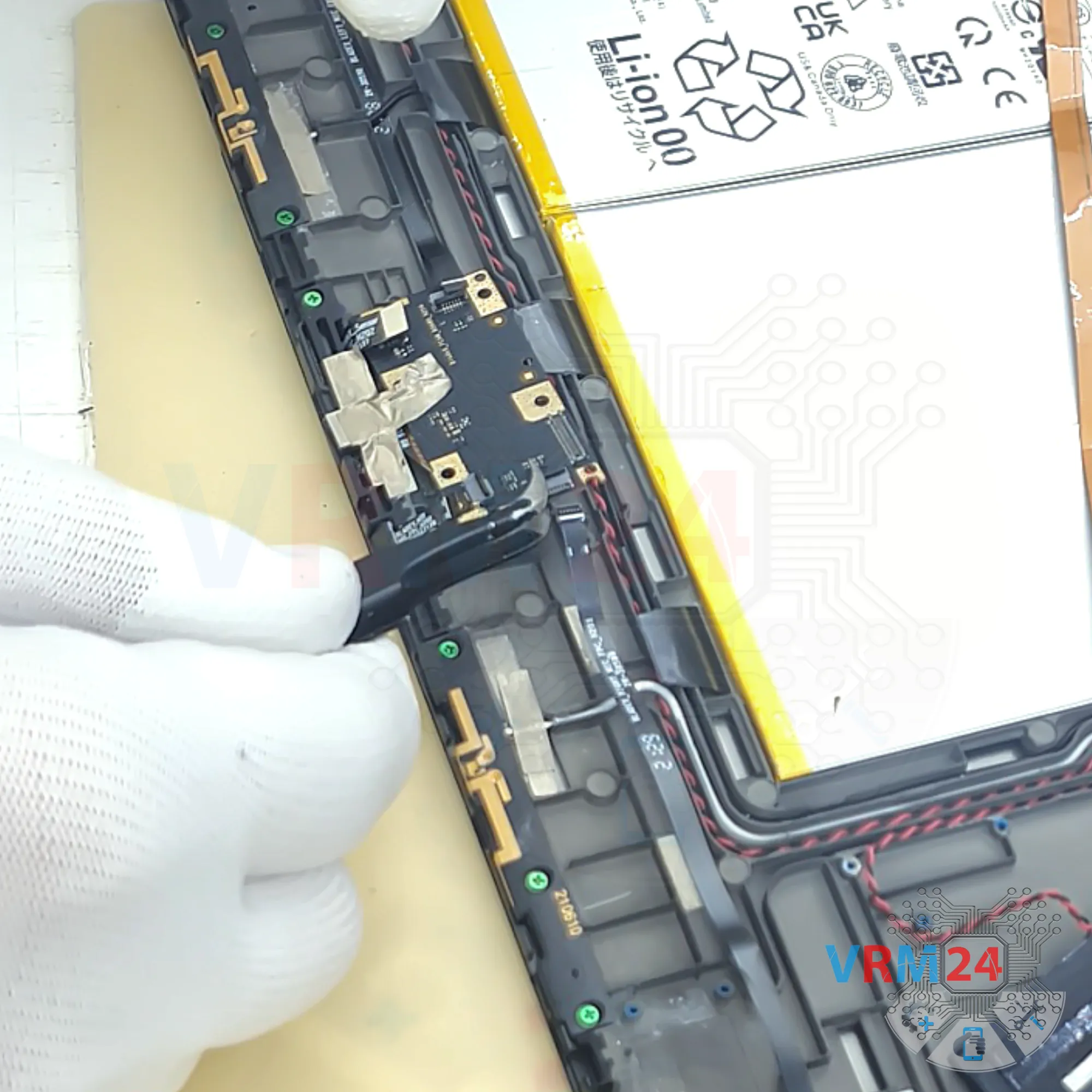
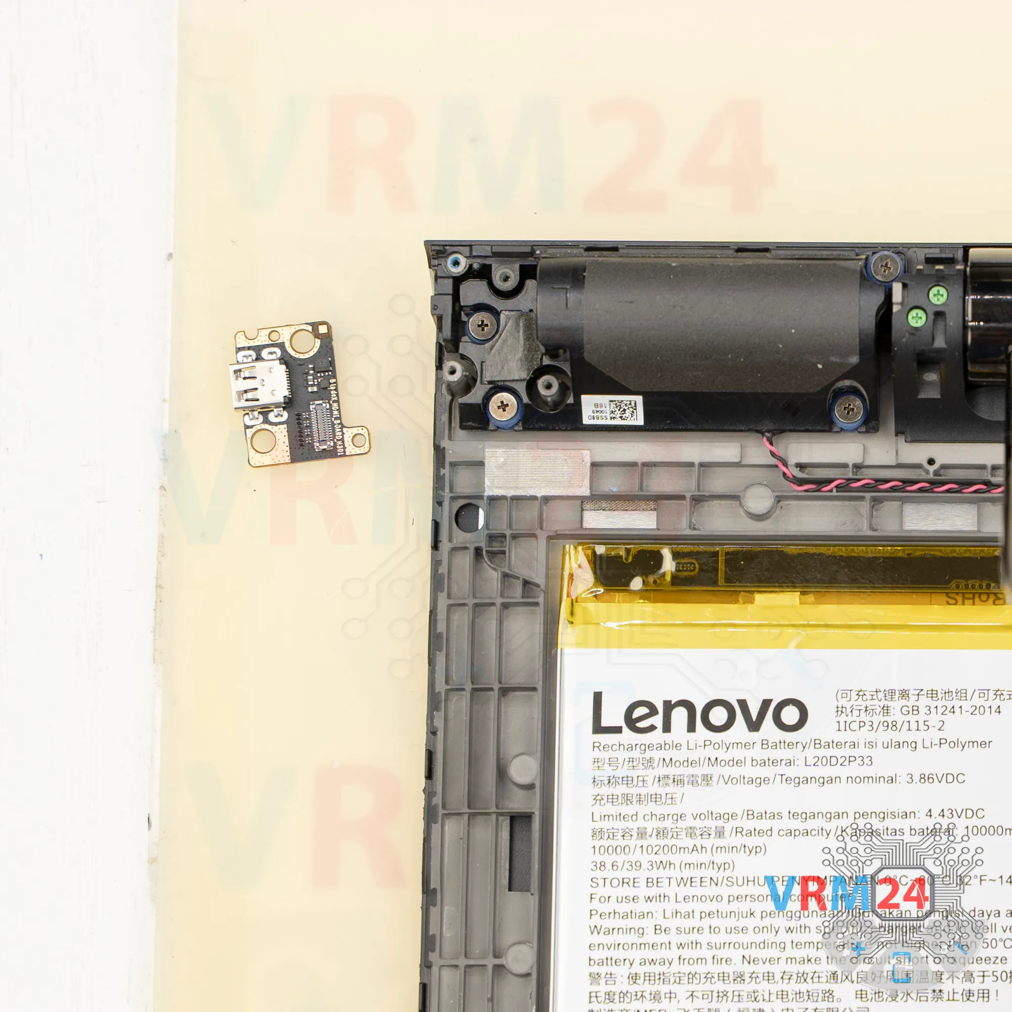
Step 10. Disconnect the connector
Carefully peel off the flex cable, lift the circuit board, gently flip it, disconnect the inter-board flex cable, and set the circuit board aside.


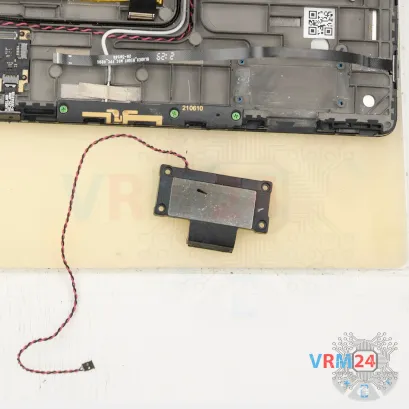


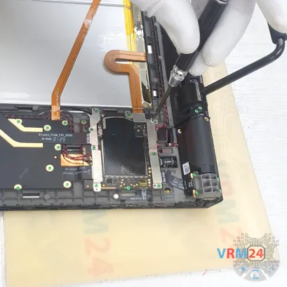
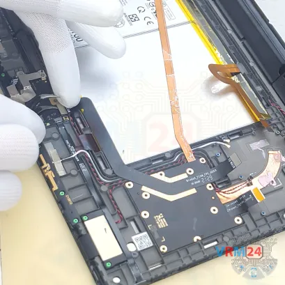
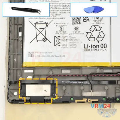
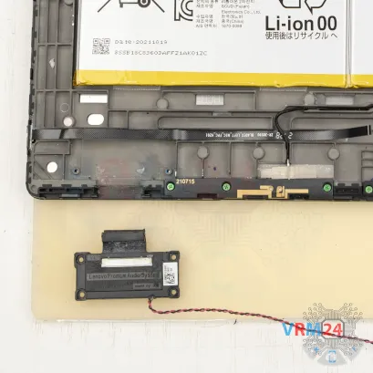
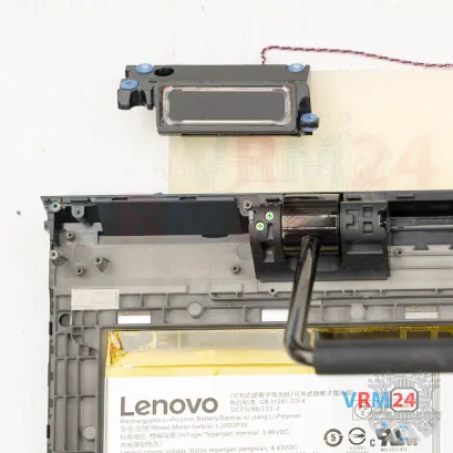
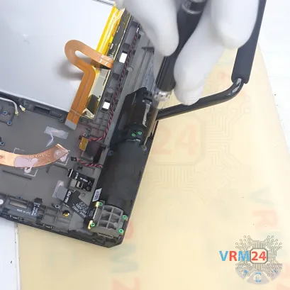
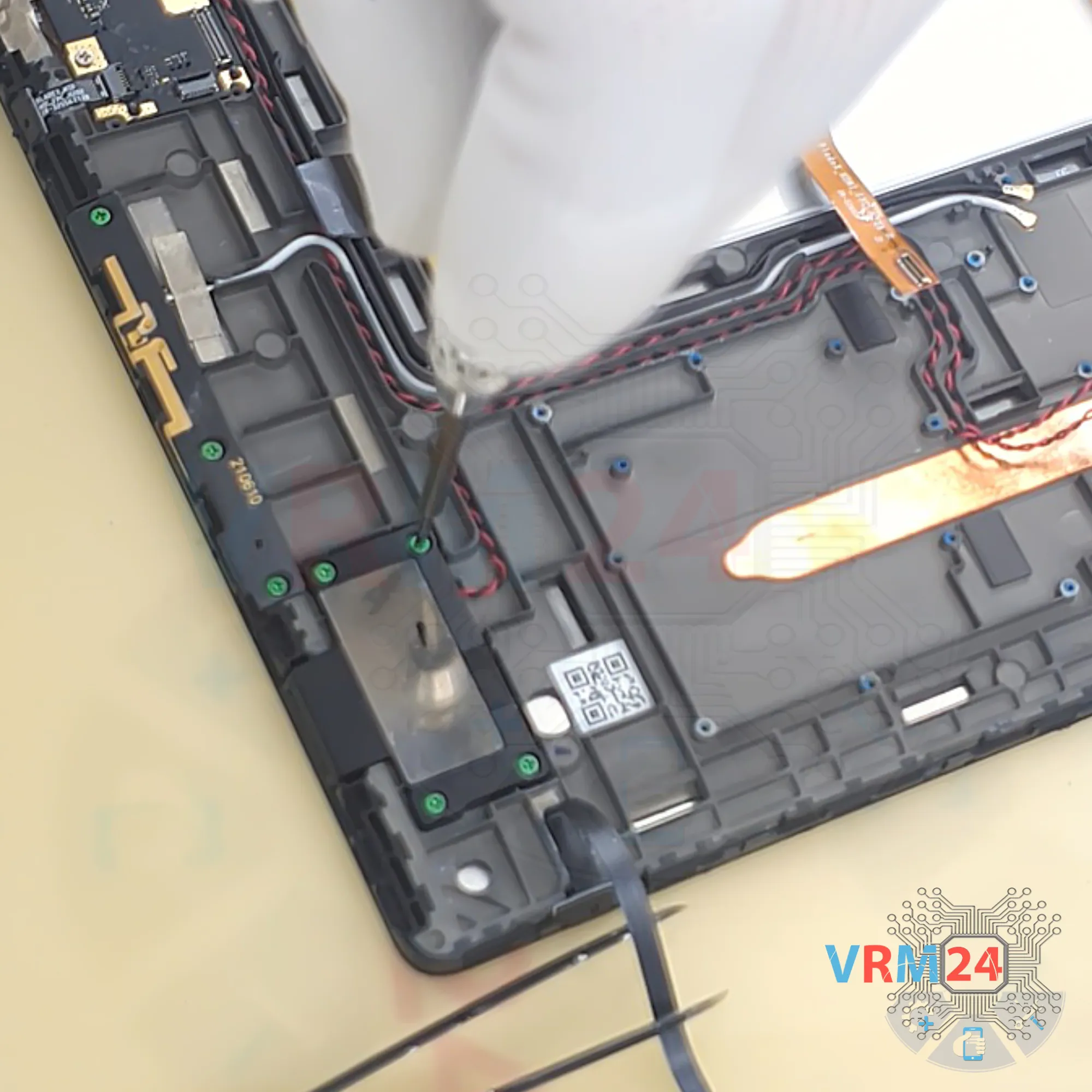
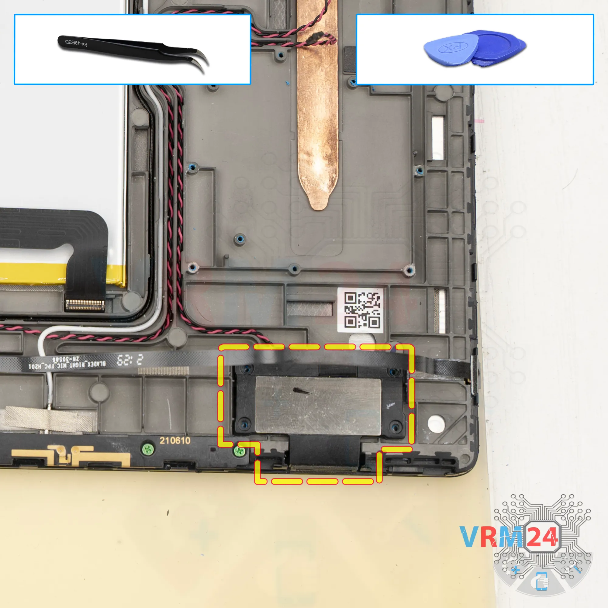
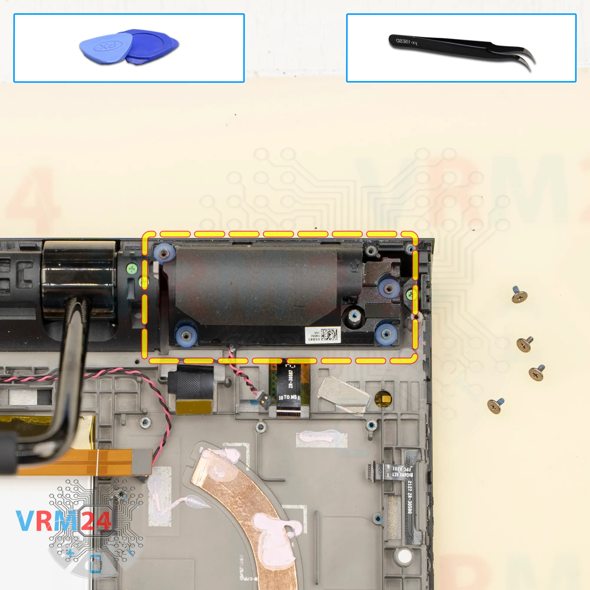
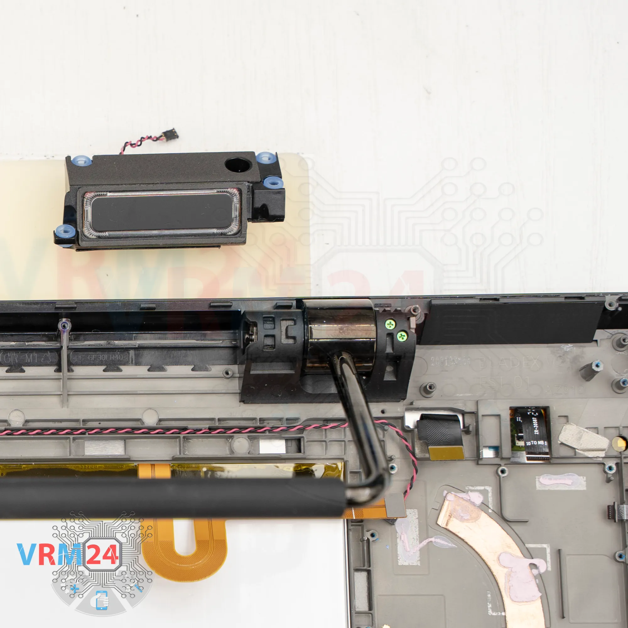
Step 12. Remove the loudspeaker
The speakers in the lower part are glued, so we need a special tool.
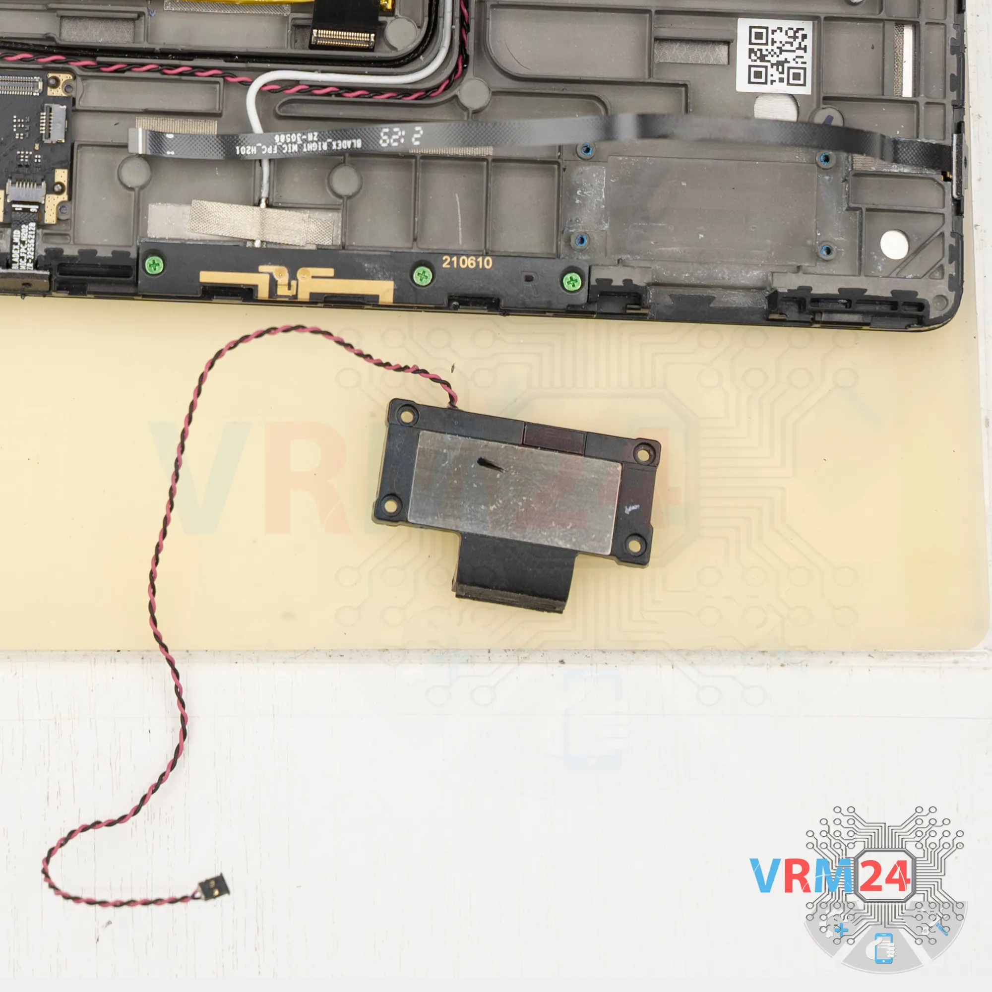
Carefully lift the bottom part and remove the speaker, setting it aside.
Then release the speaker cable from the grooves that hold it in the display frame.

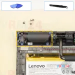
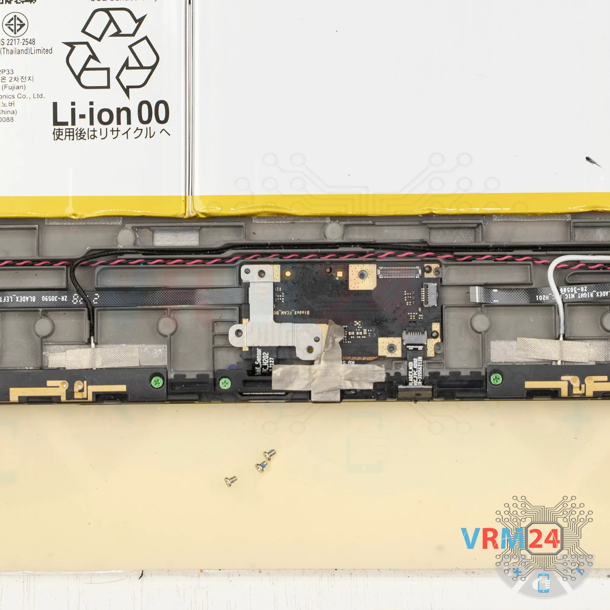
Step 13. Unscrew the screws
Next, unscrew the three screws holding the sub-board and remove the bracket.


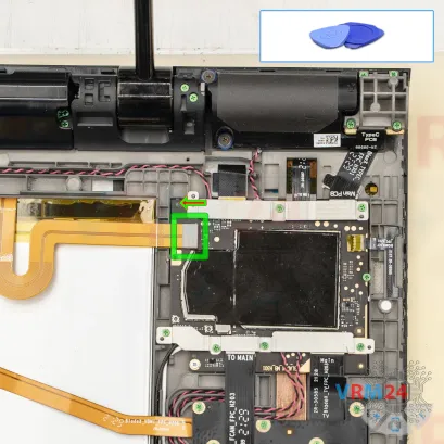
Step 14. Disconnect the connectors
Then we disconnect the two cable connectors for sensors and microphone cable connector.

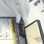
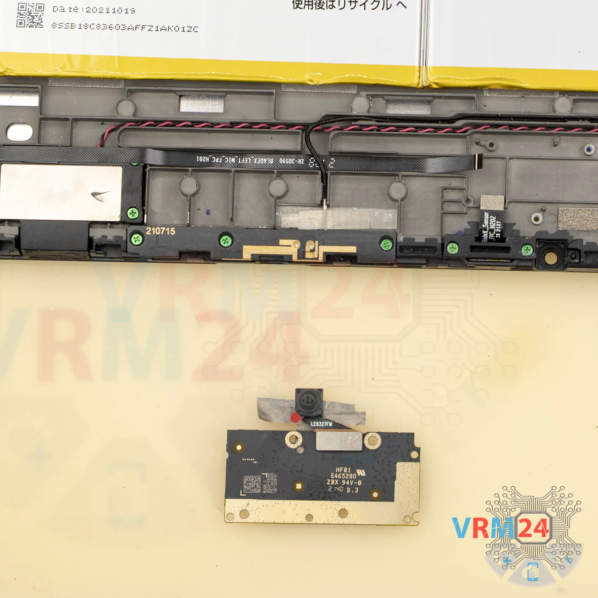
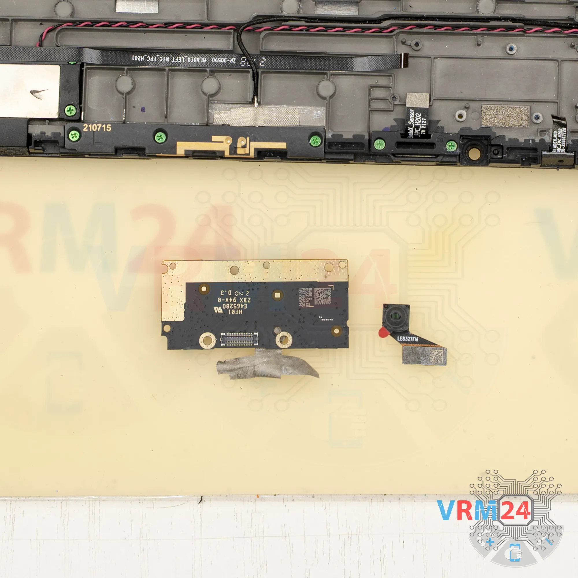
Step 15. Remove the front camera
We also peel off the adhesive film that holds the front camera in place.


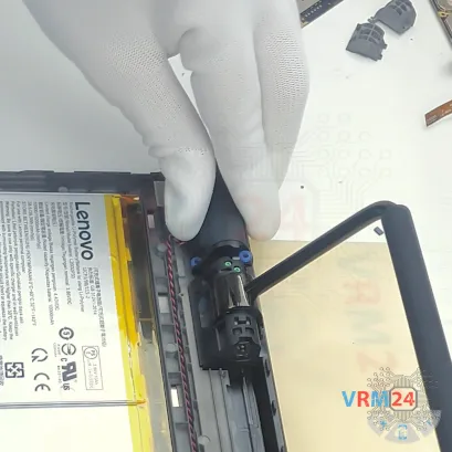
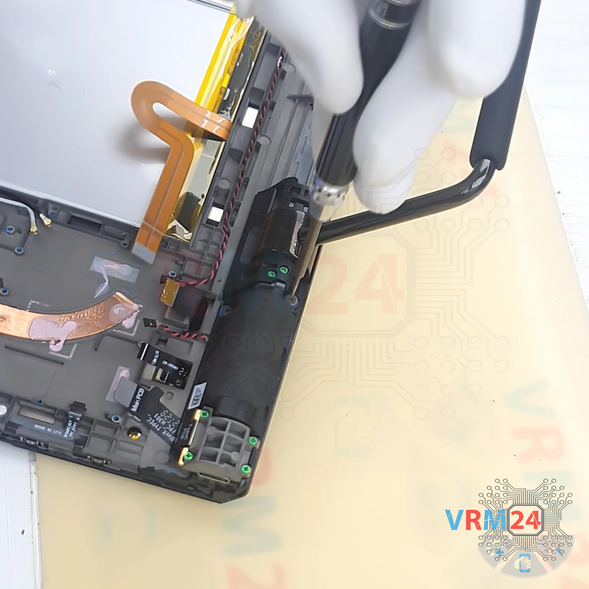
Step 17. Remove the loudspeaker
Then use a special tool to lift and disconnect the speaker, which is also glued.
It’s not very strongly glued, but you still need to be careful.
Lift it carefully—the flex cable may get in the way. Gently wiggle and remove the lower speaker, then fold it aside.


Step 18. Unscrew the screws
Unscrew the four screws that secure small circuit board and remove the cover.


Step 21. Unscrew the screws
Using a screwdriver Phillips 1.5 mm (PH #000), unscrew the four screws.
They have large flat heads, are short, and they are different from the others.
Remove the loudspeaker and set it aside.

Step 22. Open the cover
We can remove the middle section near the handle. It’s held by three screws.


Step 23. Unscrew the screws
Unscrew the four screws that hold the small board in place and remove the cover. Use the same Phillips #000 screwdriver.


Step 26. Unscrew the screws
And again - using a screwdriver Phillips 1.5 mm (PH #000), unscrew the four screws.
They have large flat heads, are short, and they are different from the others.
Remove the last loudspeaker and set it aside.


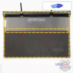
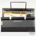
Step 27. In the display frame remained
ℹ️️ In the display frame remained: the battery, microphones, cables.
Detailed disassembly instructions of Lenovo Yoga Pad Pro 13 in the video, made by our mobile repair & service center:
If you have a question, ask us, and we will try to answer in as much detail as possible. If this article was helpful for you, please rate it.

Disassembling\Repair has easy complexity and takes about minutes in time.
Our manual is suitable for all models Lenovo Yoga Pad Pro 13 — Lenovo Yoga Pad Pro 13 YT-K606F released for markets in different countries.
Back to the list