

⚠️️ Before disassembling, do not forget to turn your phone off.
Teardown difficulty:
Easy
Easy
Recommended tools


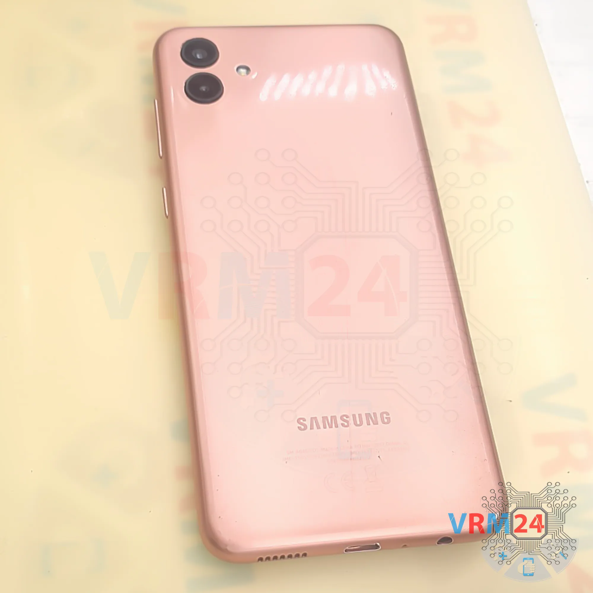
Disassembly/Repair of the mobile device Samsung Galaxy A04 SM-A045 (Samsung Galaxy A04 SM-A045F, SM-A045F/DS, SM-A045M) with each step description and the required set of tools.

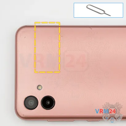

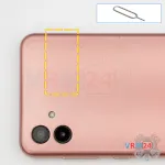


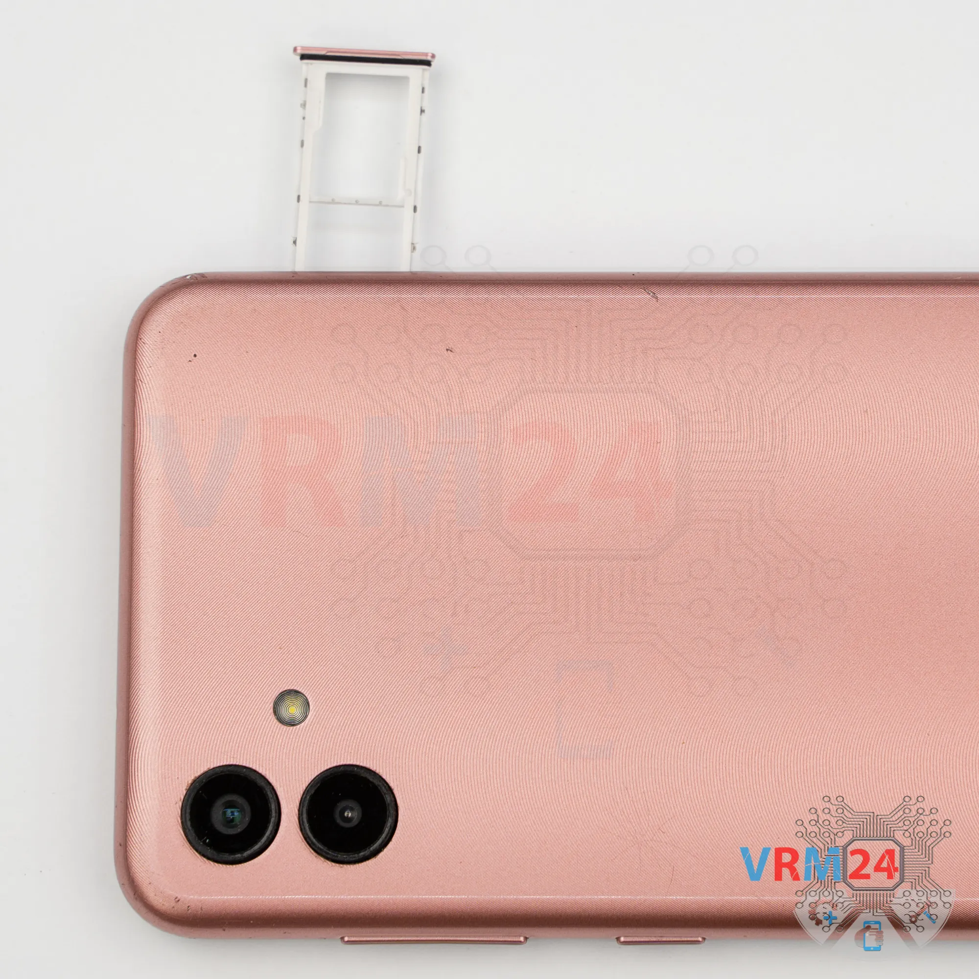
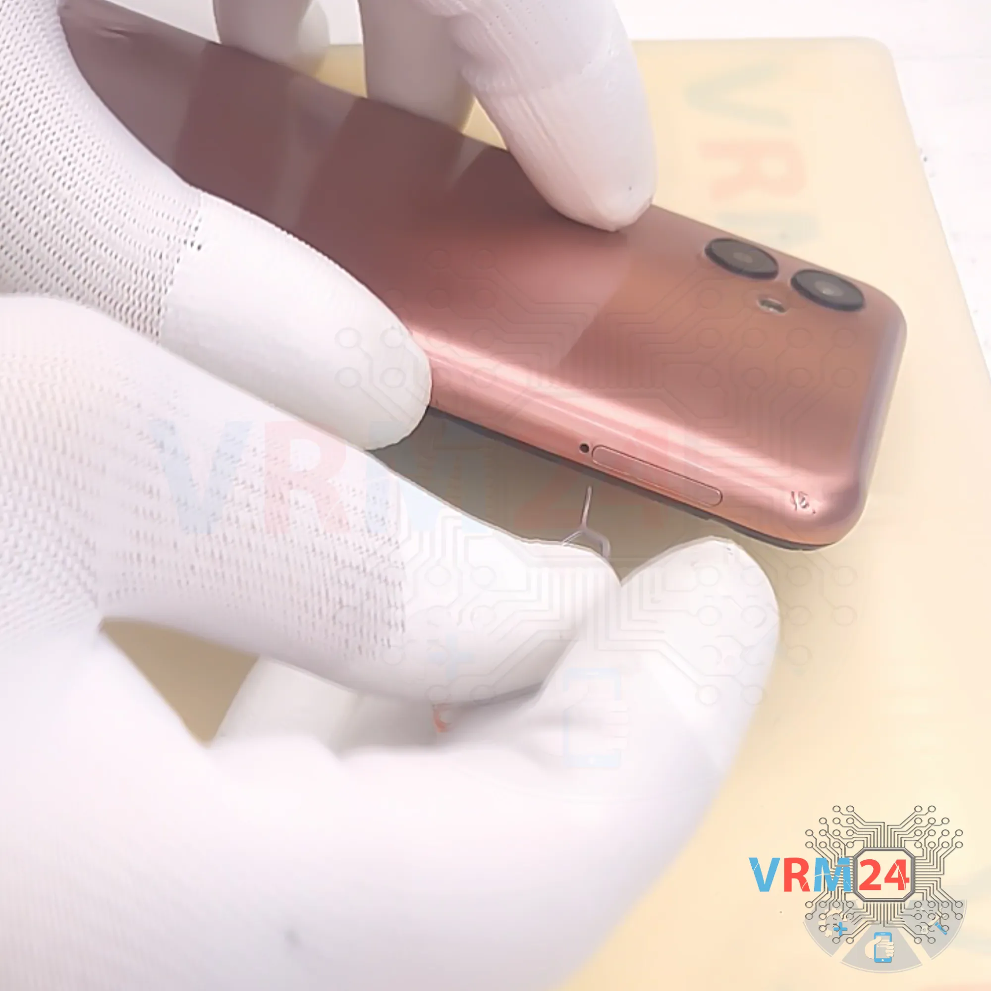
Step 2. Remove the tray
First, we need to remove the SIM tray.
For this, we use a special tool, insert it into the hole, and push the card tray out.
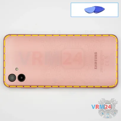


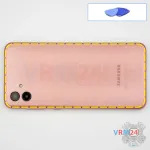


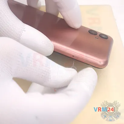
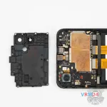
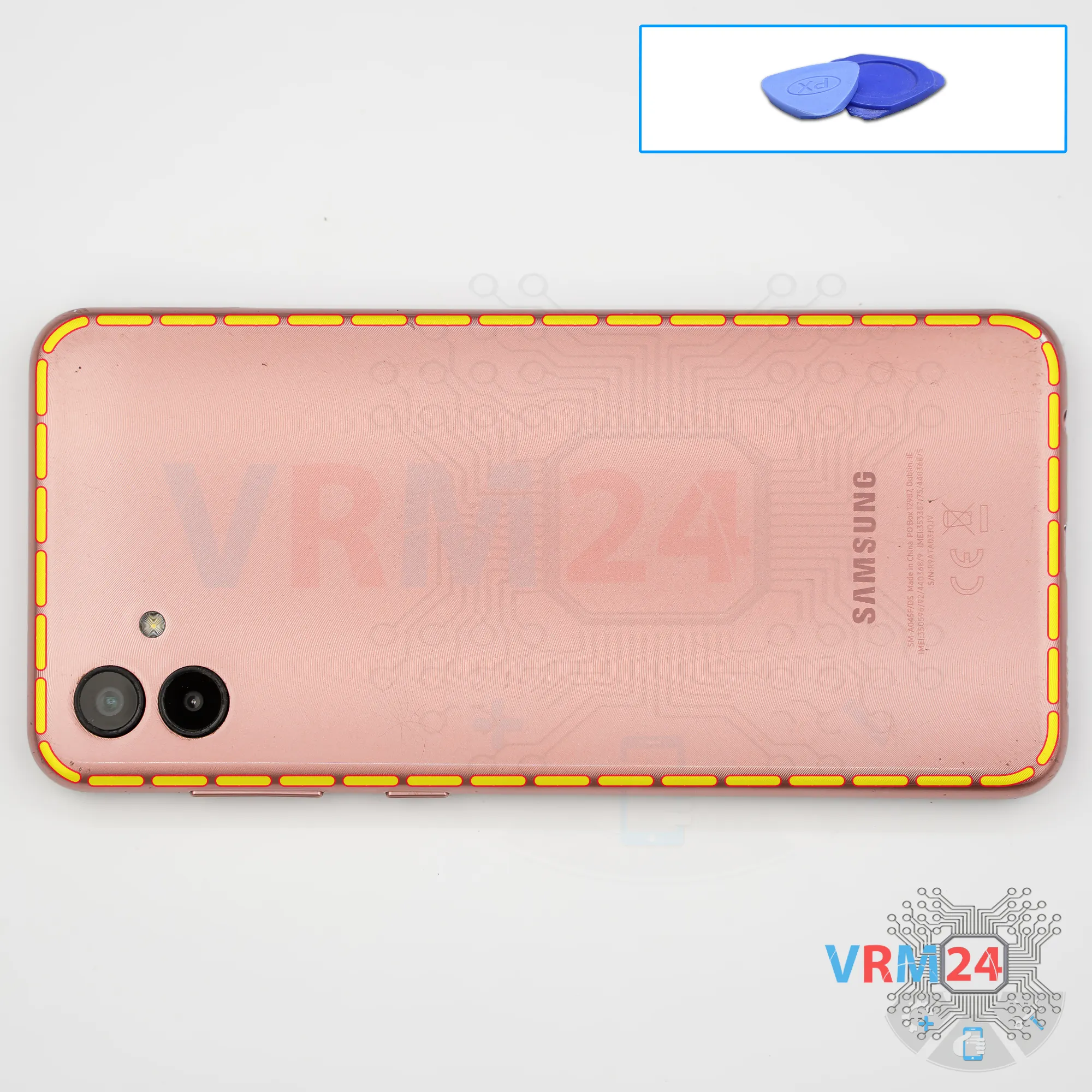
Step 3. Open the back cover
After that, using a thin tool or a piece of plastic film, we need to release a few clips.
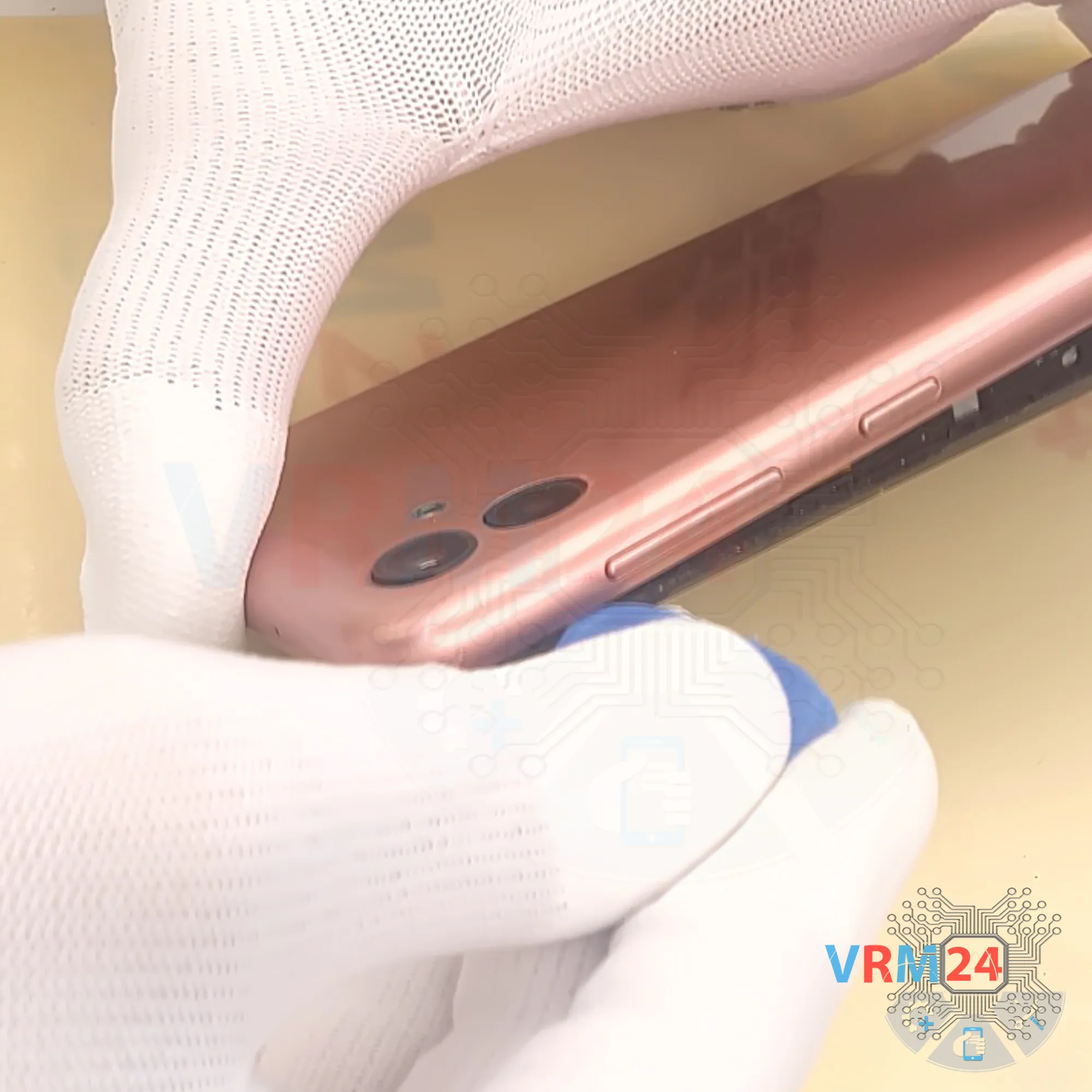
We insert the film into the gap between the back cover and the display frame near the SIM tray opening, disconnect a few clips, and then we can switch to using a thicker tool.
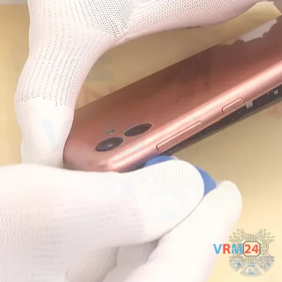
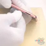
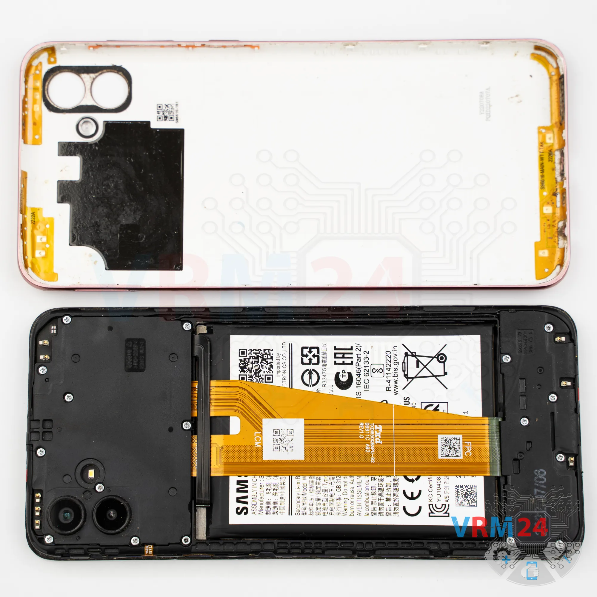
Carefully work our way around the edge. We need to be very careful around the side buttons because they are physically located there.
And as we can see, the antenna traces are placed inside the back cover.


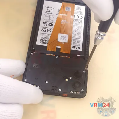

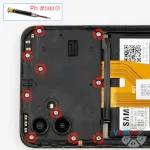


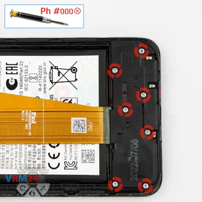
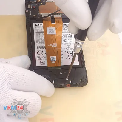
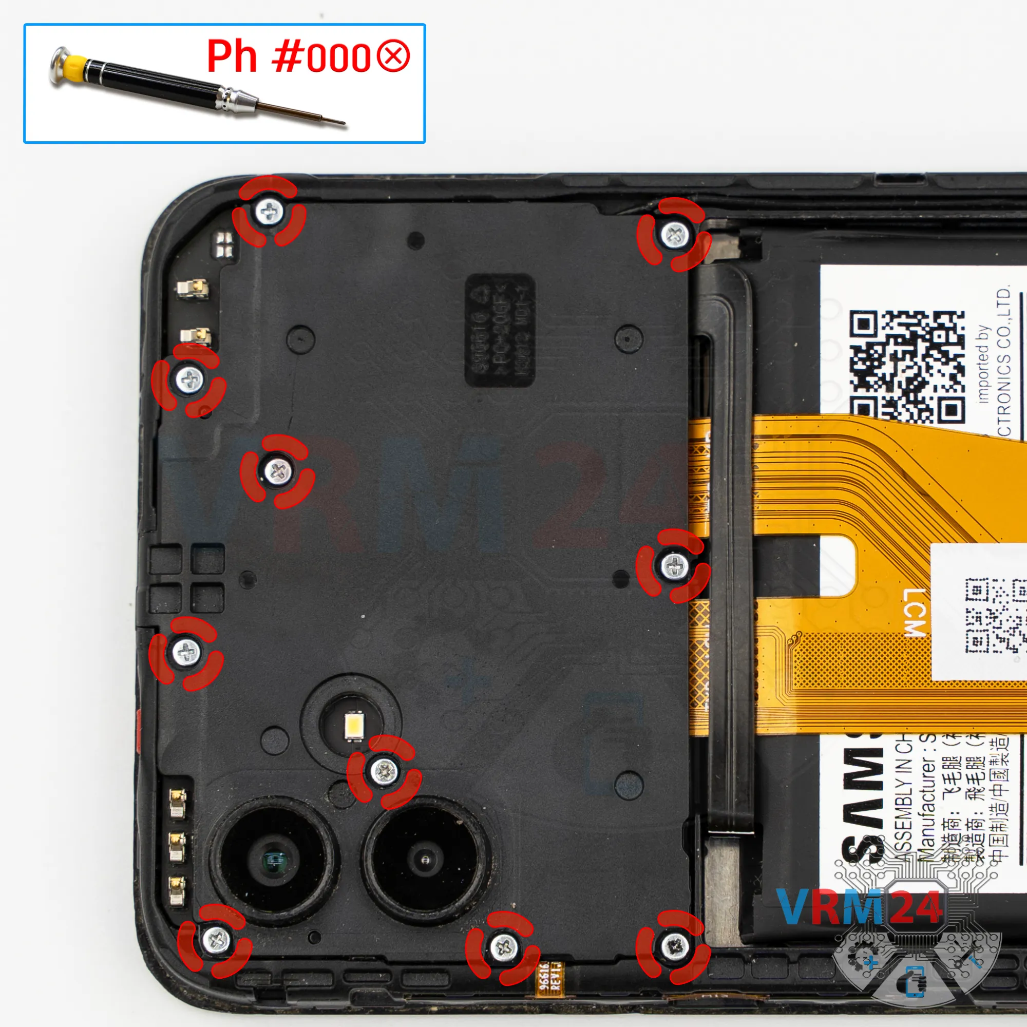
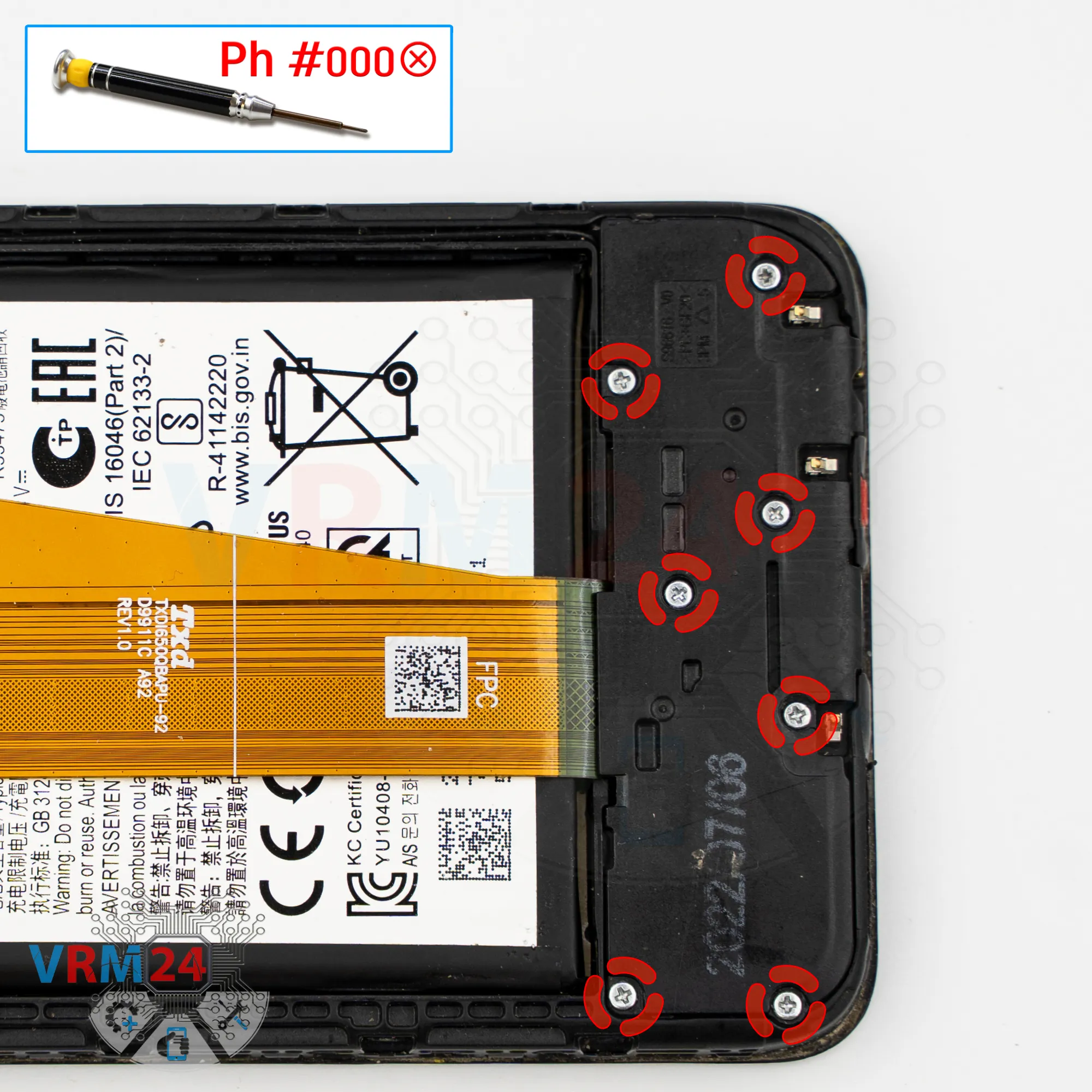
Step 4. Unscrew the screws
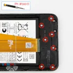
Next, we move on to removing the ten screws in the upper section.
For this, we use a 1.5 mm Phillips screwdriver or a Phillips #000.
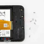
It looks like all the screws are the same, but it’s still recommended to place them on a special surface in a specific order for reassembly.
Sometimes screws don’t thread properly if placed into the wrong hole.
Next, it’s better to cover the camera lenses.
We use a special protective film for this.
Gently cover the lenses so dust or debris doesn’t get on them.
Notice that we apply the film not onto the lenses themselves but onto the rim around them.


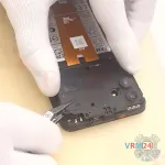
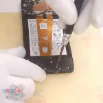
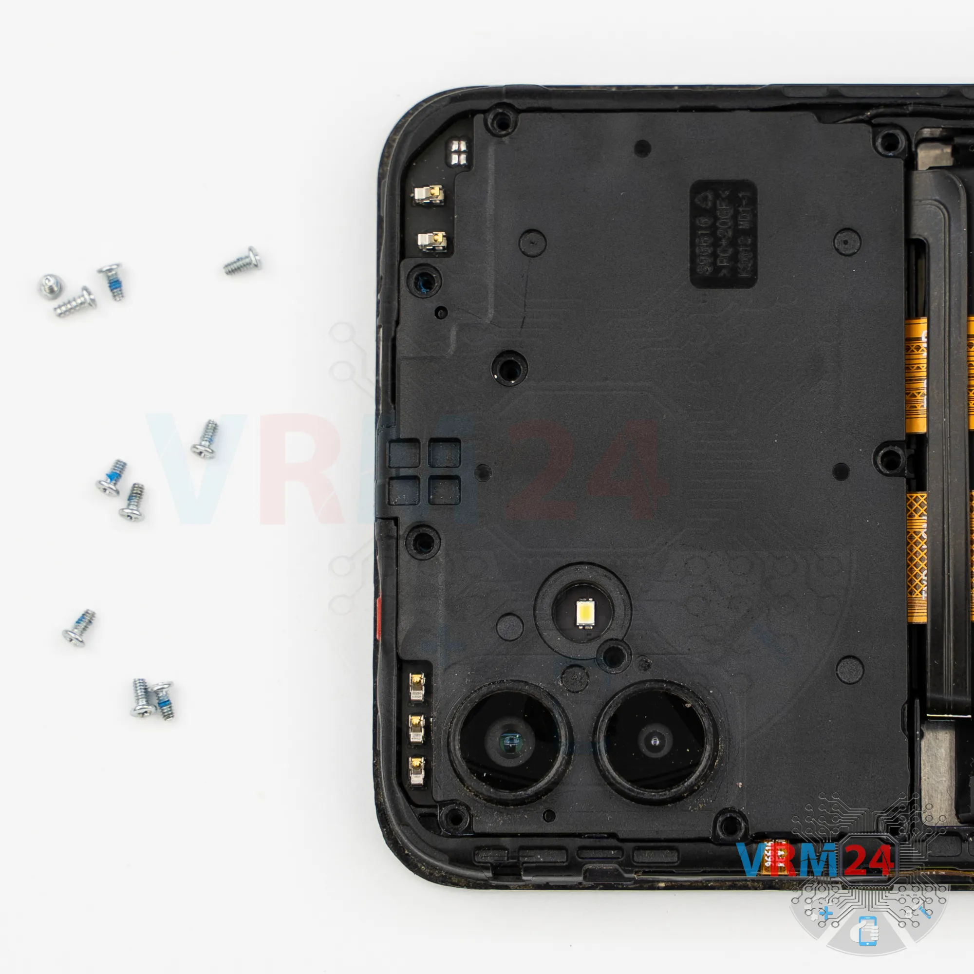
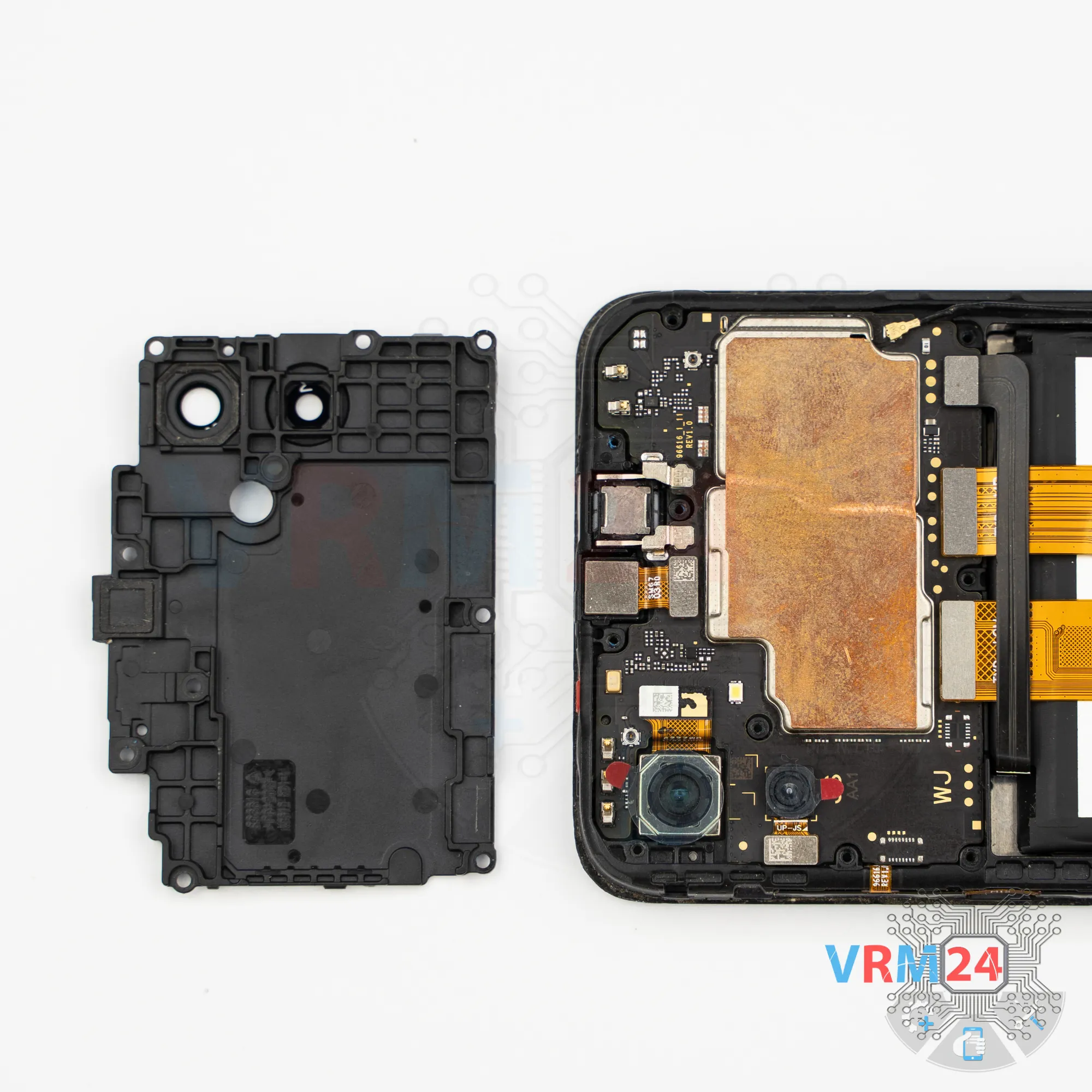
Step 5. Open the cover
Then we need to use a non-metallic tool to disconnect the upper cover. Carefully lift it from the edge, remove the cover, and set it aside.


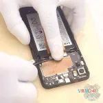
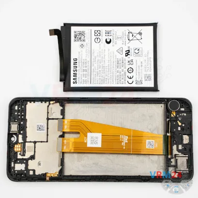
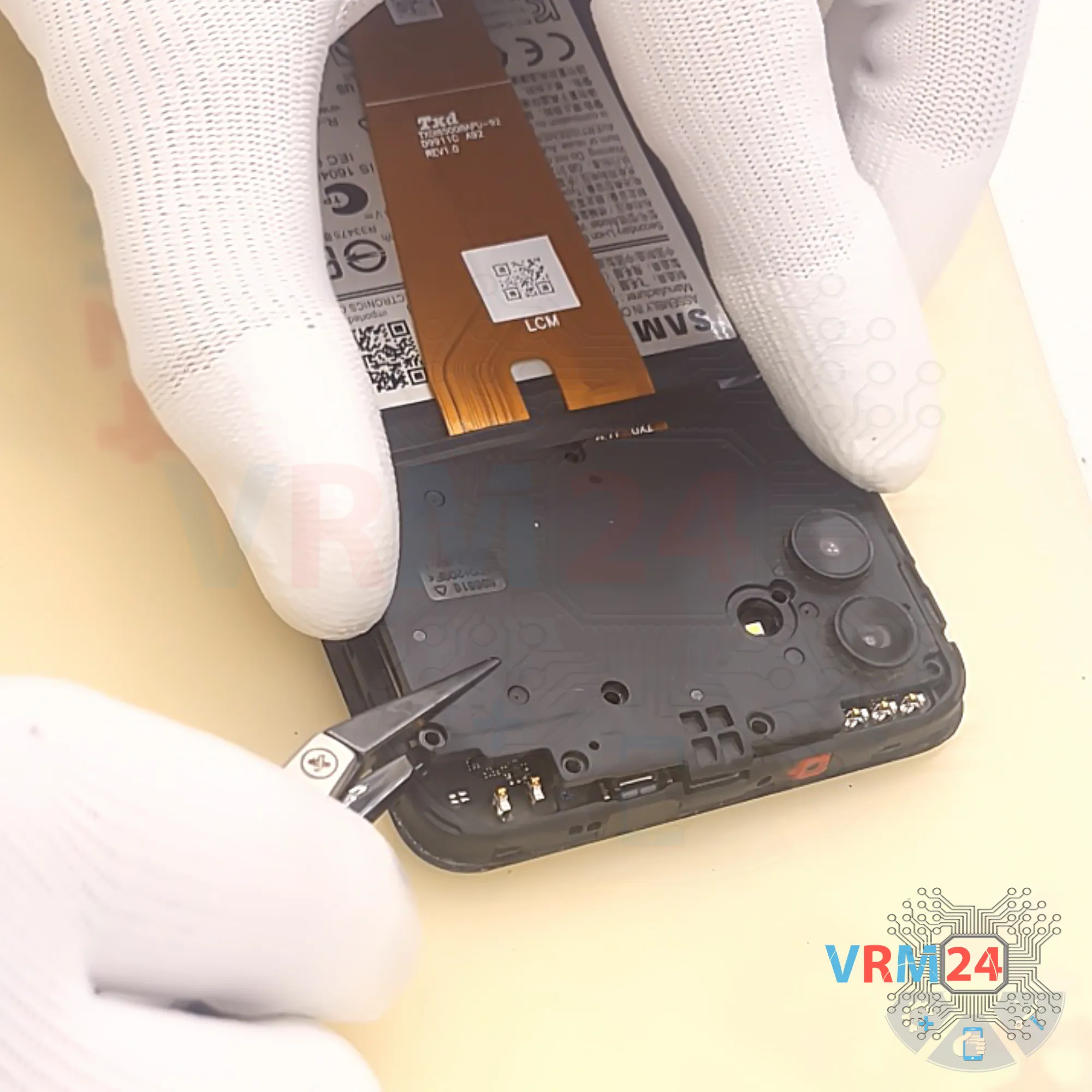
Step 6. Disconnect the battery connector
After this, we also use a non-metallic tool to disconnect the battery connector.
ℹ️️ The Samsung Galaxy A04 SM-A045 uses a WT-S-W1 rechargeable battery with a capacity of 5000 mAh.

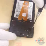
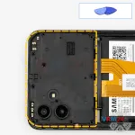
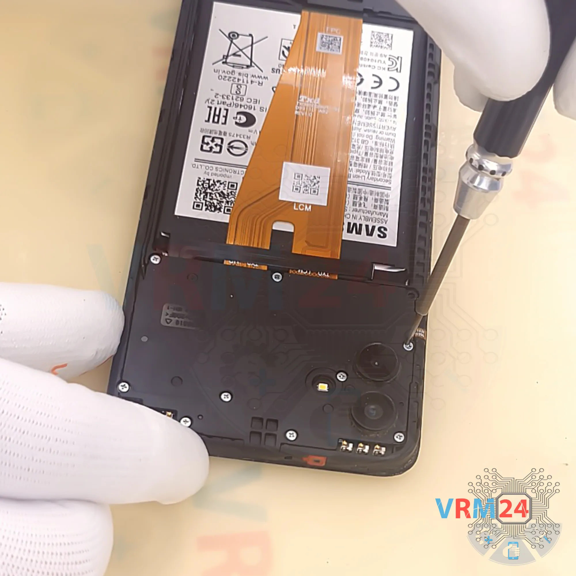
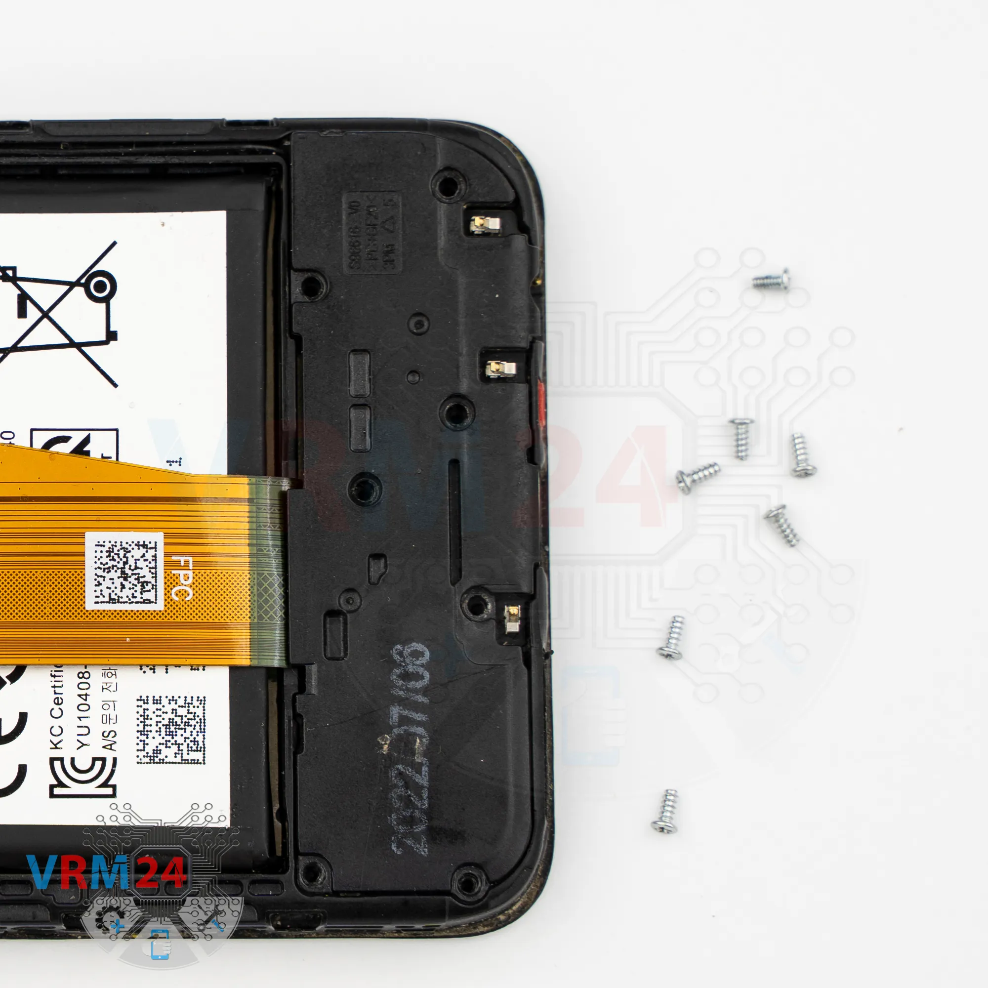
Step 7. Unscrew the screws
Now we move to the bottom section and remove the screws.
The screws in the lower part look similar to the ones from the upper part, but it’s best to keep them separate just in case.
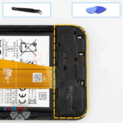
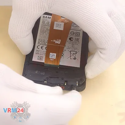


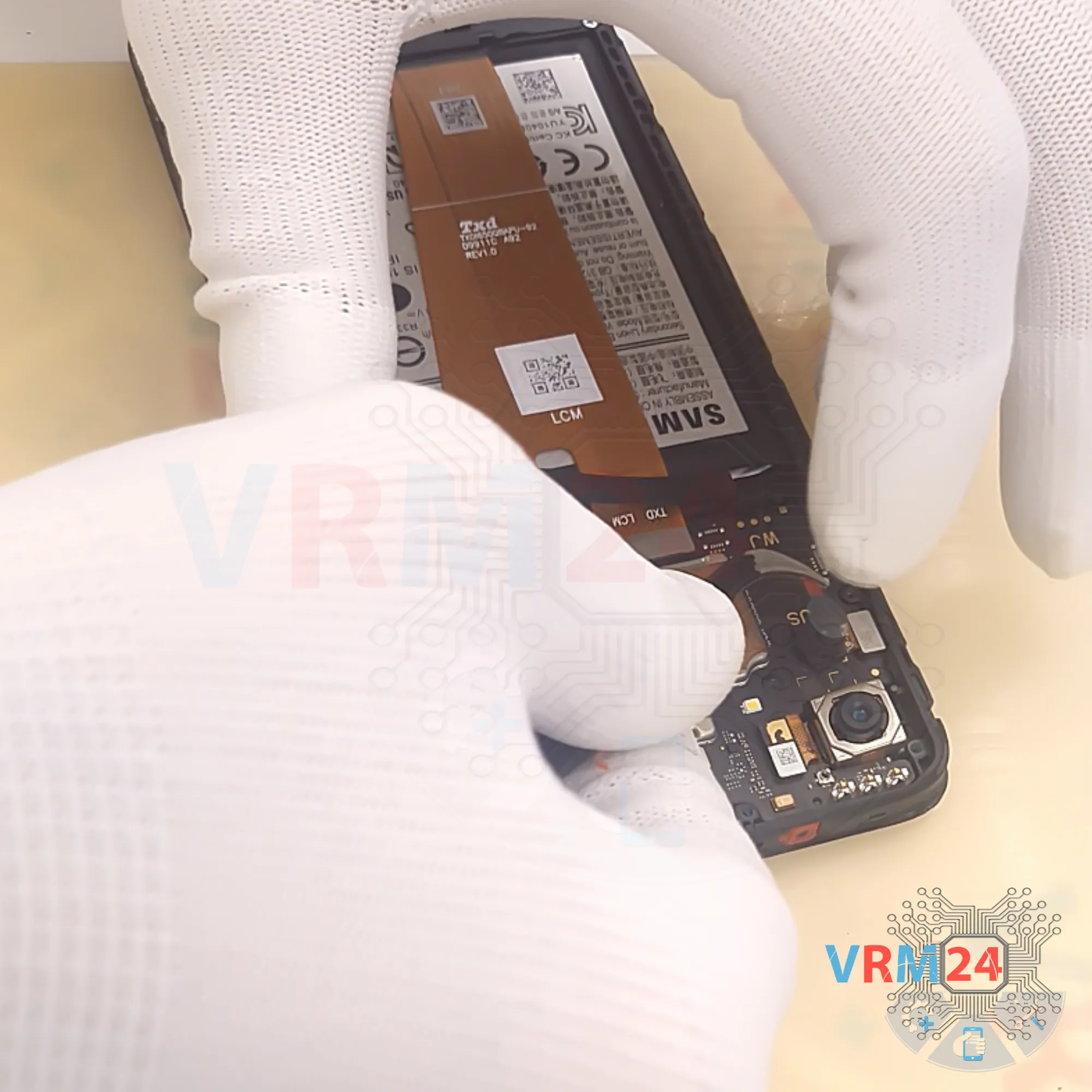
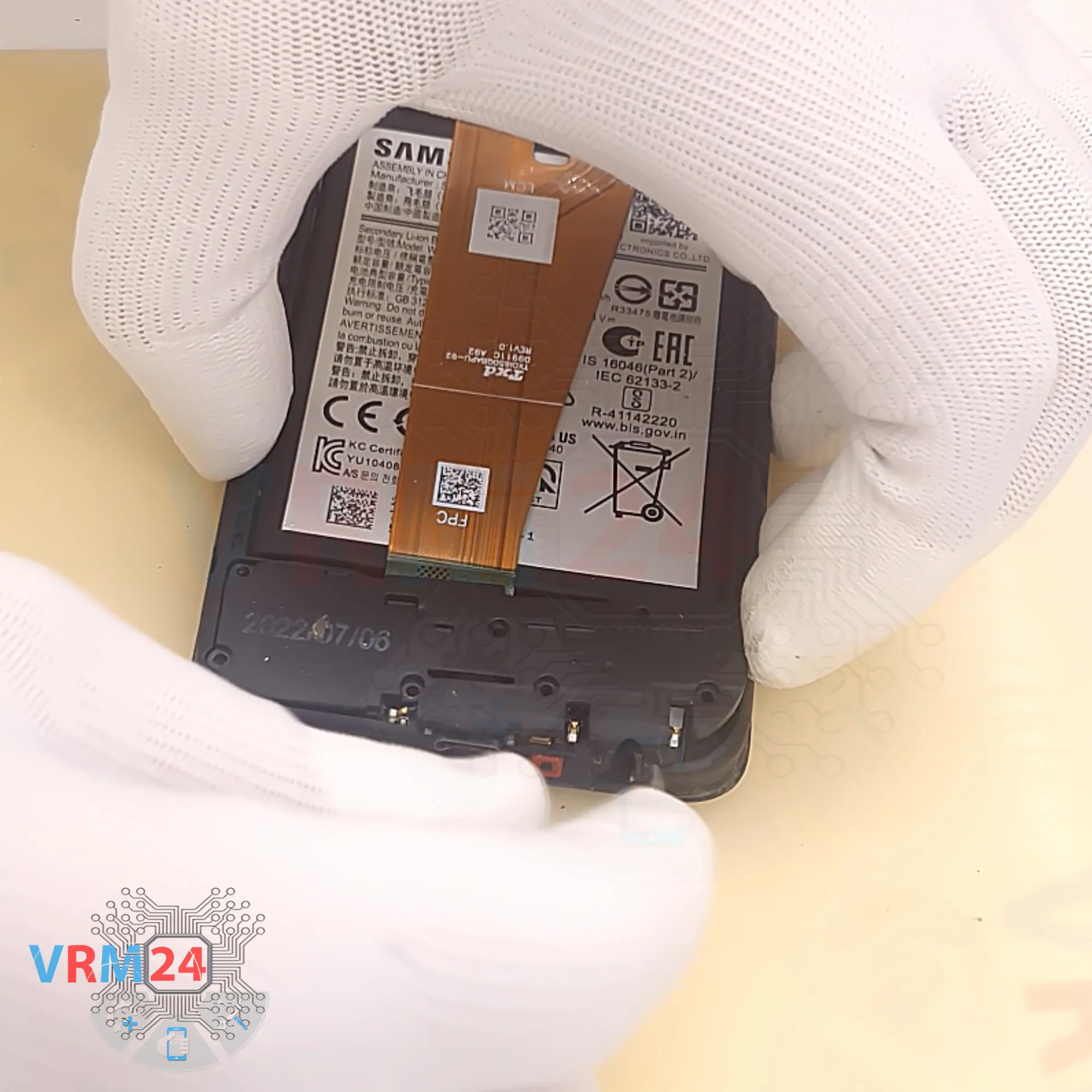
Step 8. Open the cover
Then we proceed to disconnecting the bottom cover. We find the right spot to pry, carefully lift it, and remove the cover.
As we can see, the cover has contact pads.
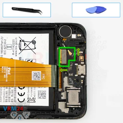

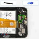
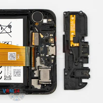
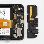
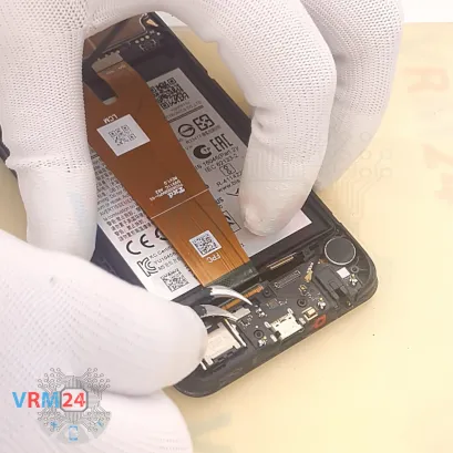
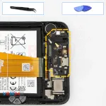
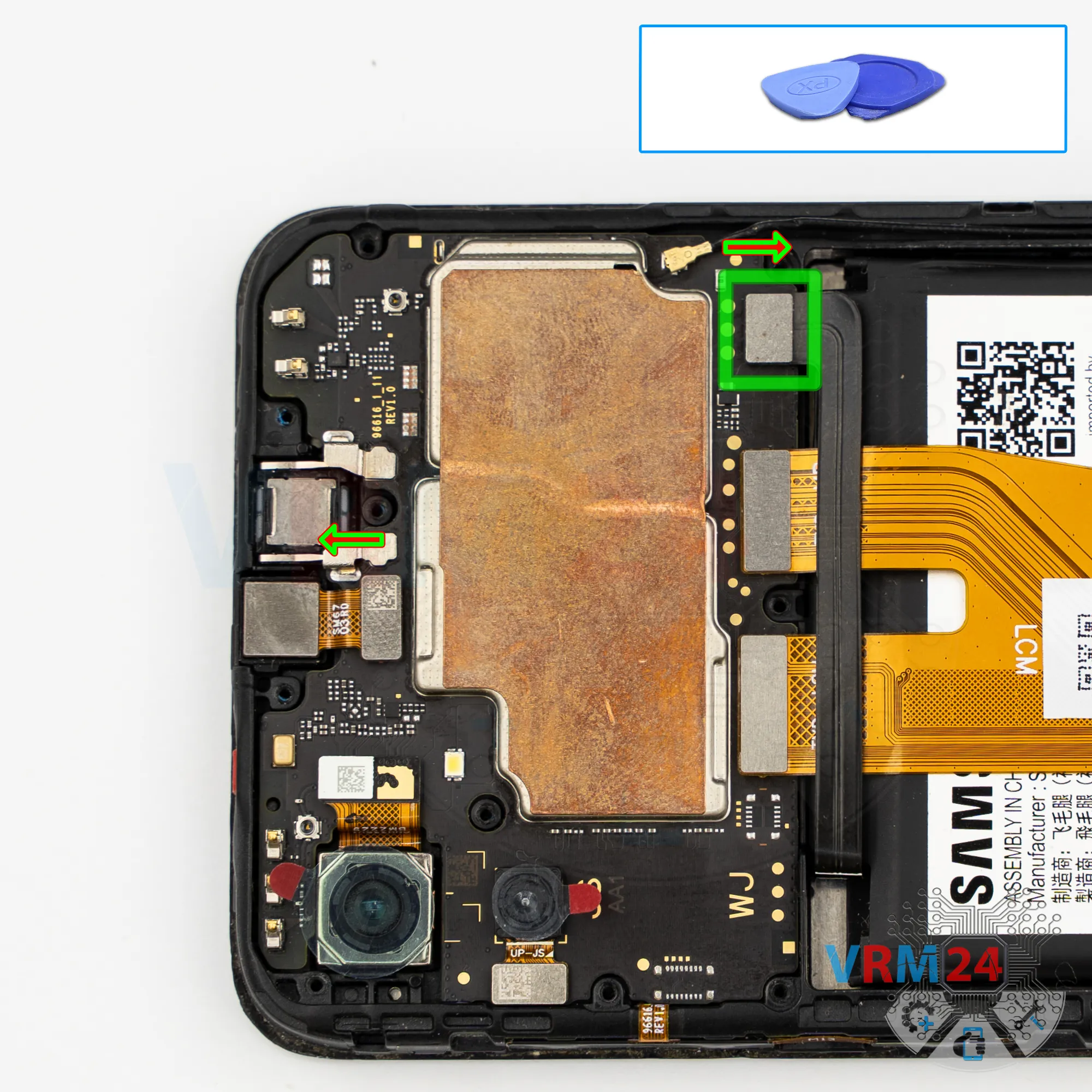
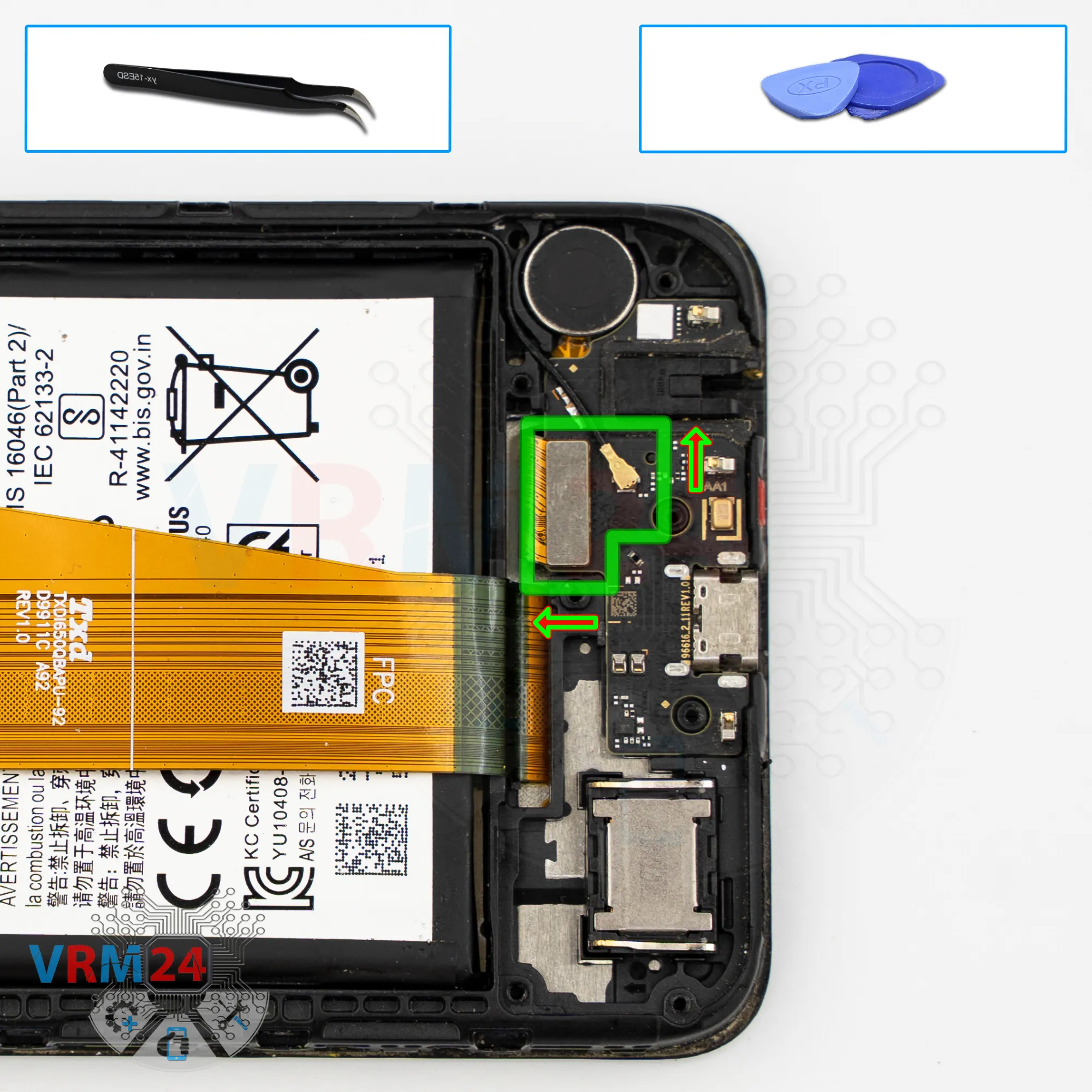
Step 9. Disconnect the connectors
Next, we disconnect the coaxial cable connector and the display flex connector.
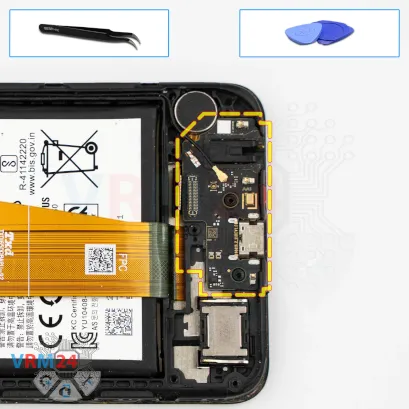
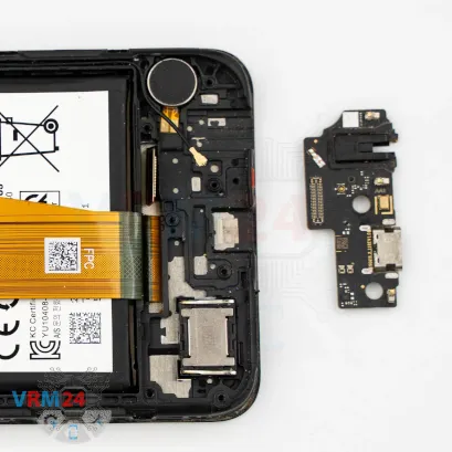
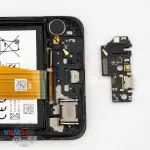

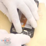
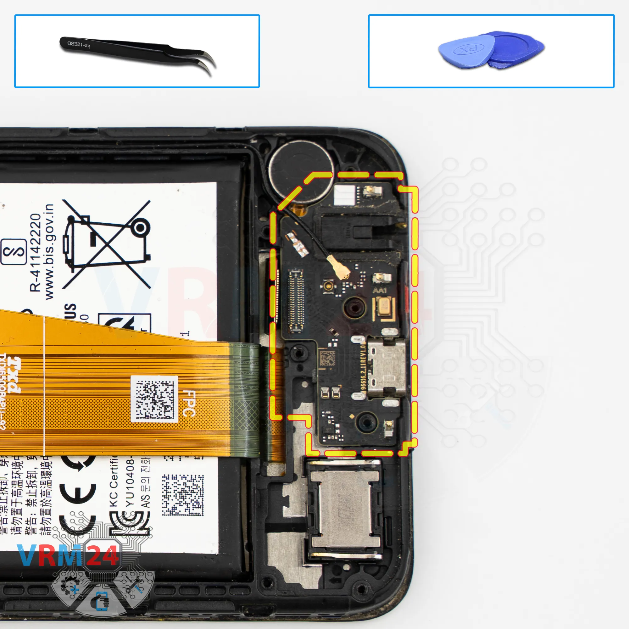
Step 10. Remove the sub-board
Carefully pry it up and take it out — the sub-board includes the charging port, microphone, headphone jack, and other components.
In the display frame, we are left with the speaker and the vibration motor.

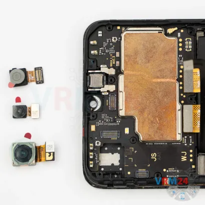

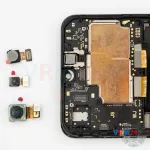

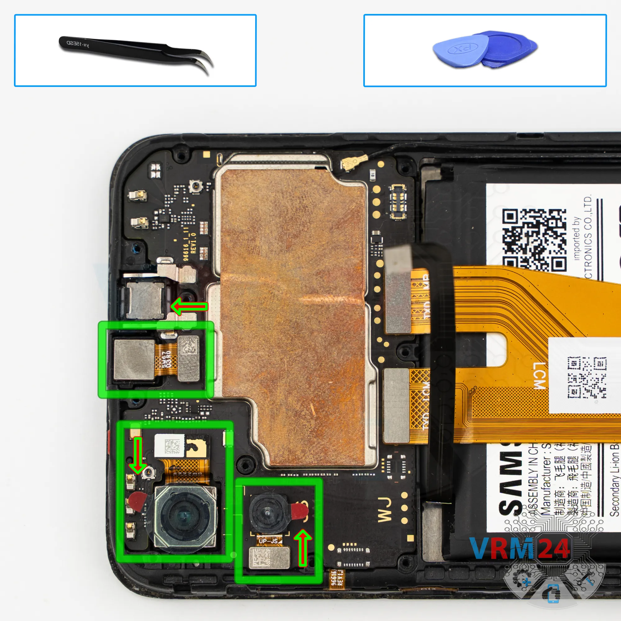
Step 11. Remove the cameras
After that, we move back to the upper part.
We need to disconnect the cameras — carefully lift them, remove them, and set them aside.
We also disconnect the front-facing camera.
It’s also better to cover its lens with protective film so dust or debris doesn’t get on it. Set the camera aside.
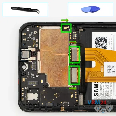

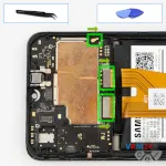
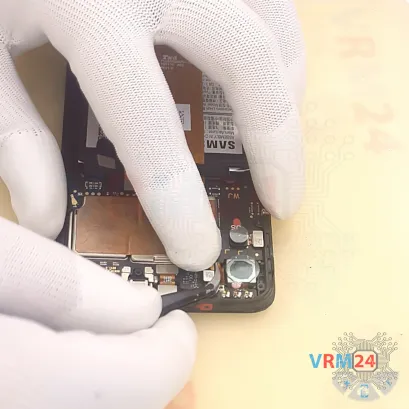
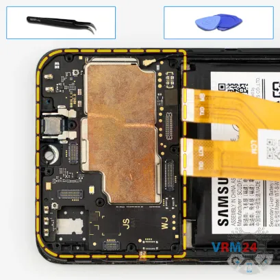
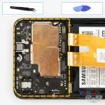
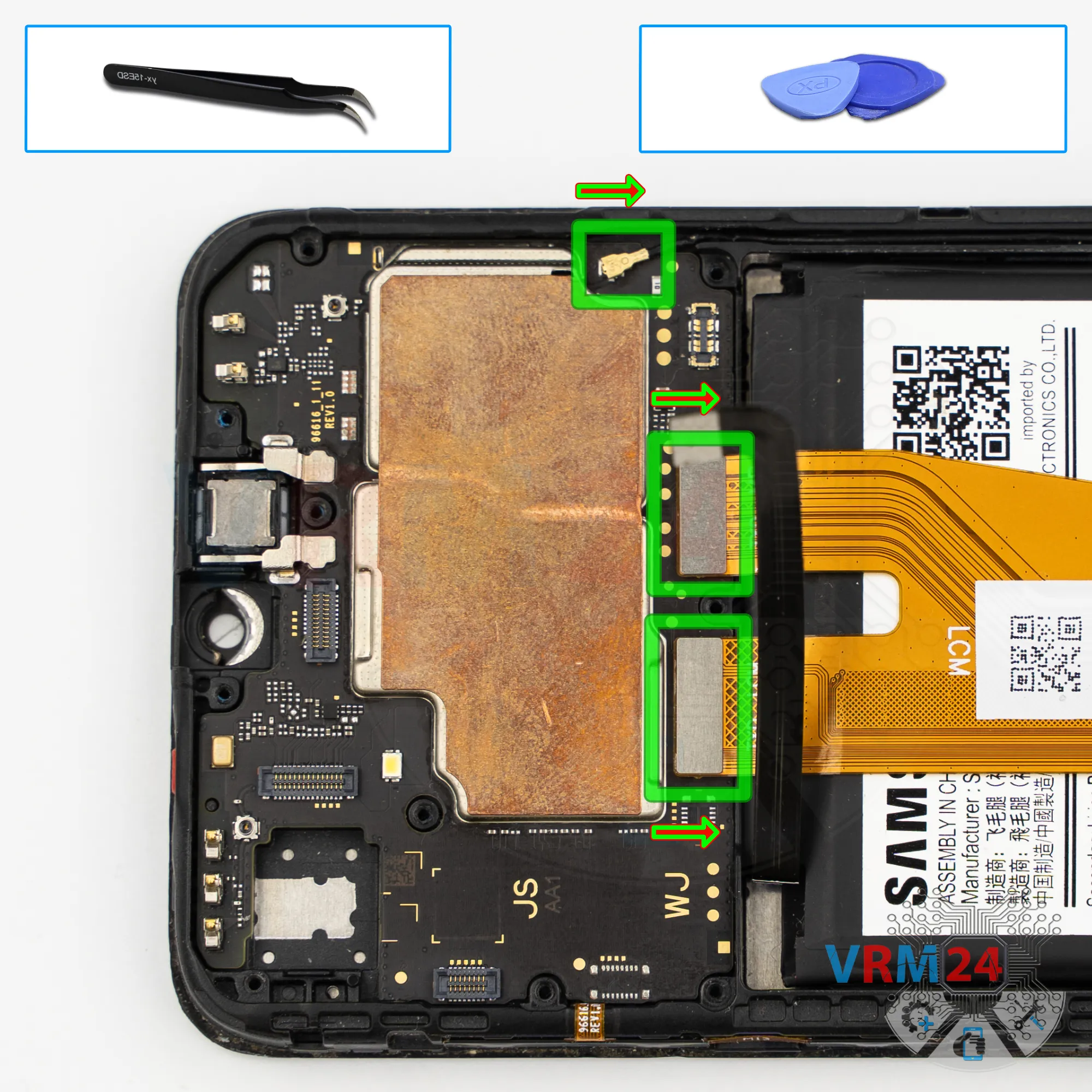
Step 12. Disconnect the connectors
Now we can disconnect the interconnect flex cable connector, the display flex connector, and the coaxial cable connector.
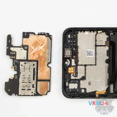

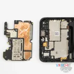
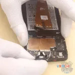
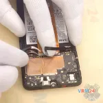
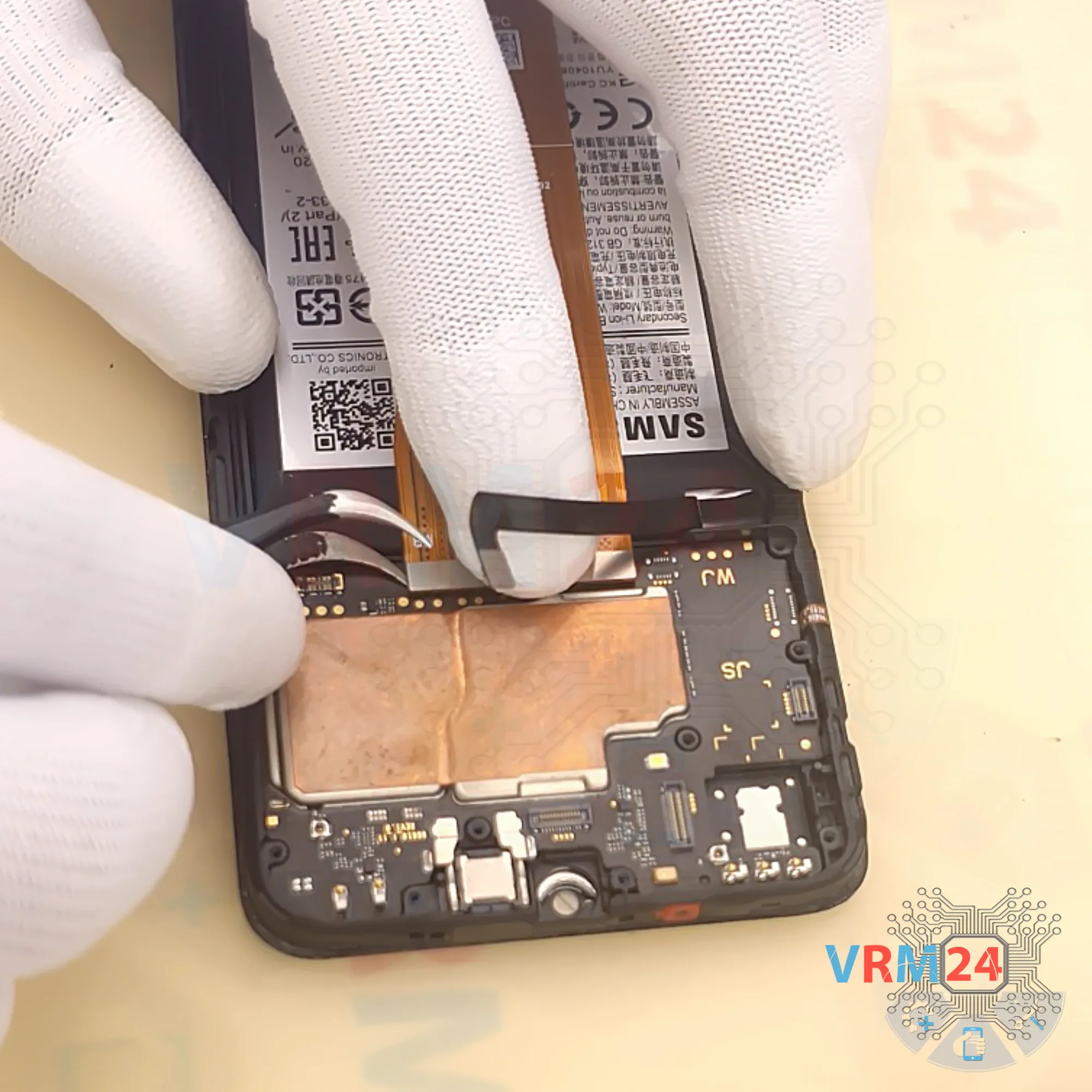
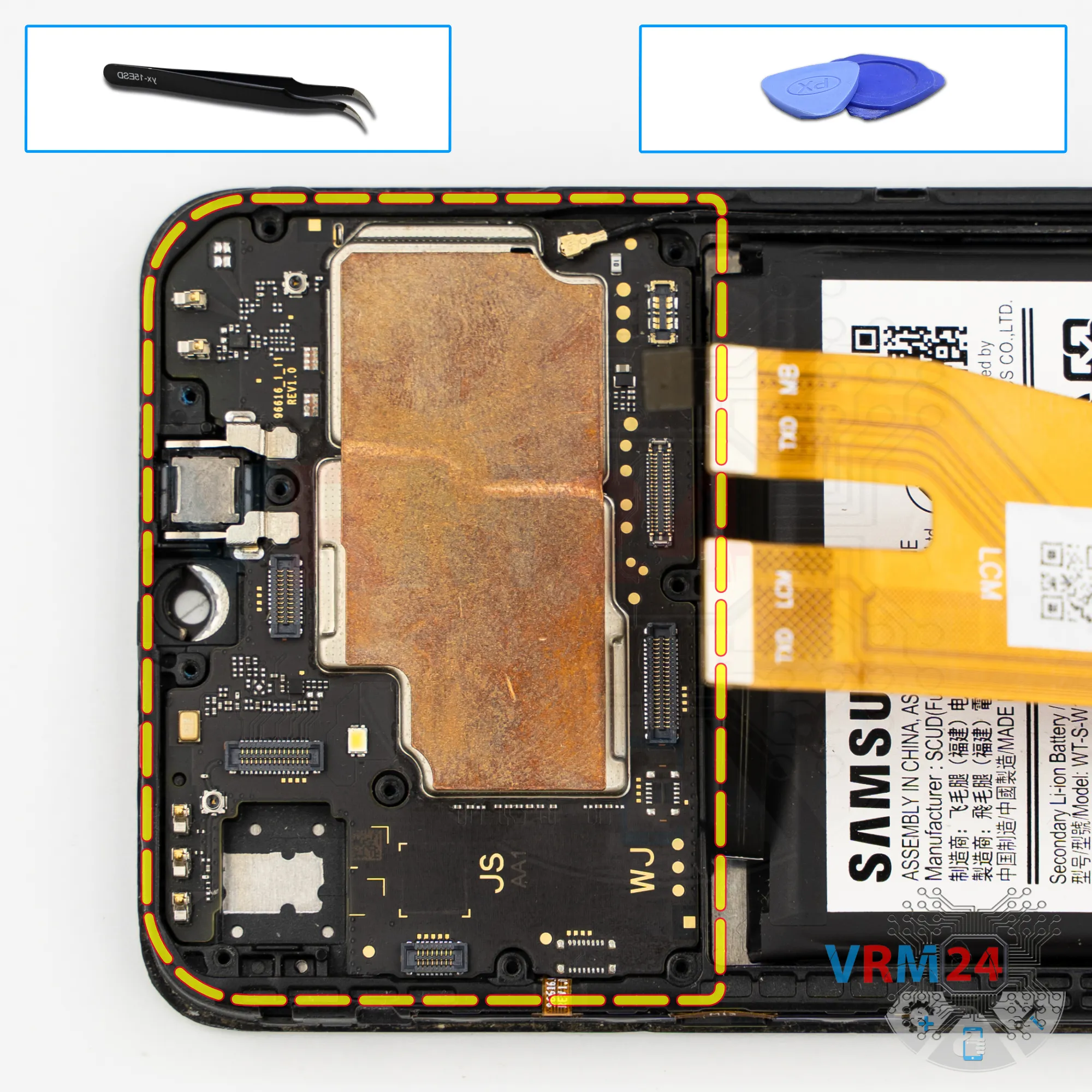
Step 13. Remove the motherboard
Then we remove the motherboard. Carefully lift it from the edge, take it out, and set it aside.
⚠️️ Do not bend the circuit board when removing it or push tools under it. Unbeknownst to yourself, you can damage components or cables from the inside.


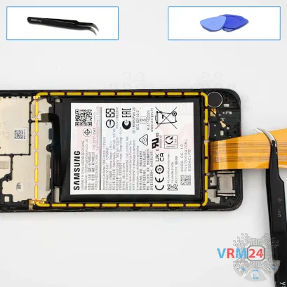
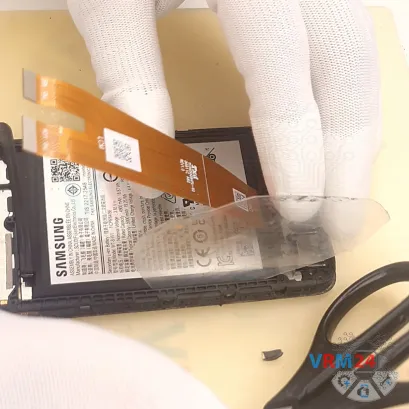
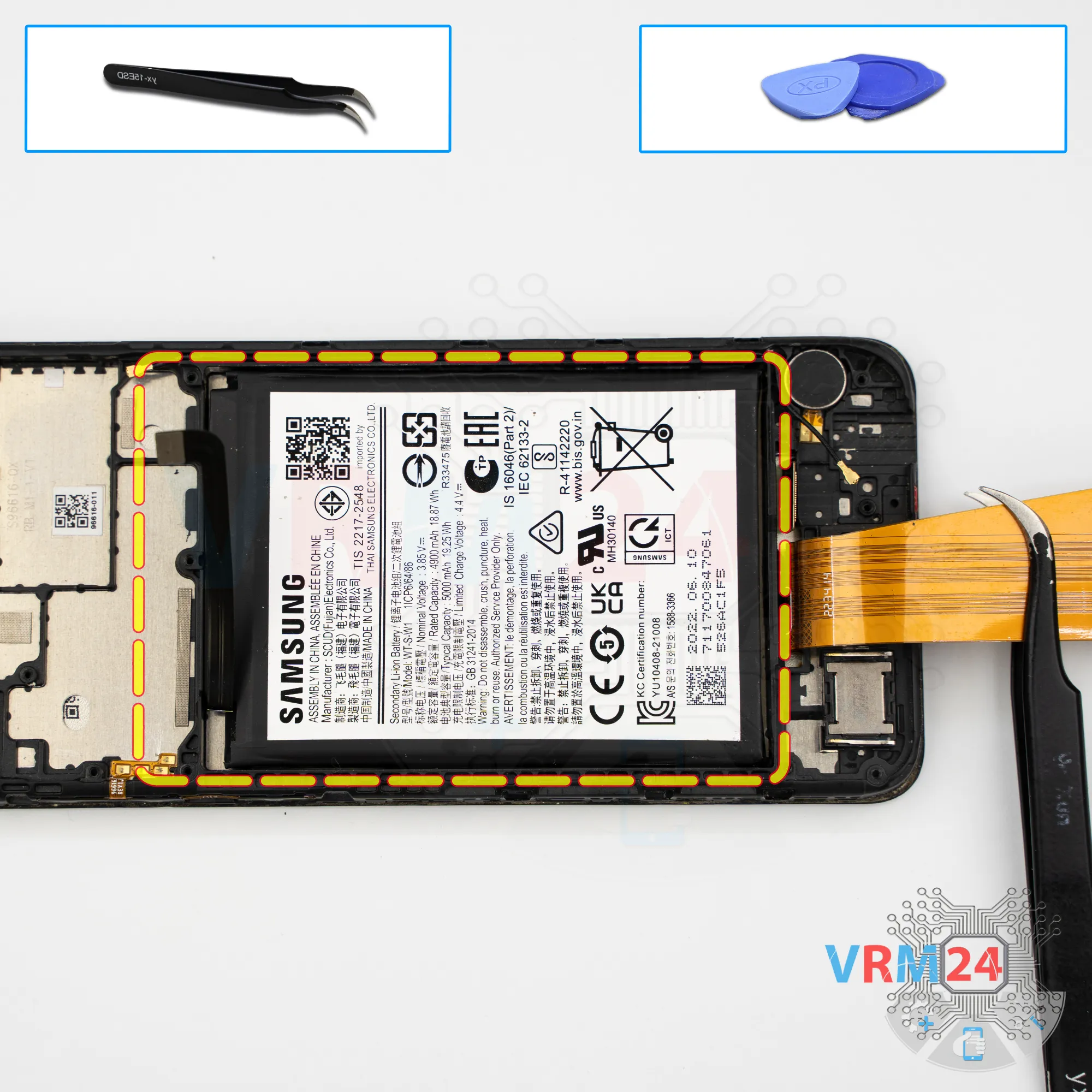
Step 14. Remove the battery
Finally, we move on to removing the battery.
Note that in our case; to remove the battery we used a thin plastic film and isopropyl alcohol.
This model has a PLS display — almost the same as IPS. This means it’s a multilayer display that can let liquid seep in. It is highly discouraged to use isopropyl alcohol on models with such displays.
In our specific case, a small amount of isopropyl alcohol is acceptable only because there are no openings under the battery that could lead directly to the display.
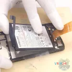
So, we apply a small amount of isopropyl to the film and gently detach the battery. Carefully work along the edges — don’t rush, don’t pull, and don’t force the battery out.
Be very careful with the interconnect flex cable located at the bottom, since it may get in the way.
Eventually, we can separate the battery.
Gently lift it, cut through the remaining adhesive under the battery so it doesn’t interfere, and remove it.
Set the battery aside.
Detailed disassembly instructions of Samsung Galaxy A04 SM-A045 in the video, made by our mobile repair & service center:
If you have a question, ask us, and we will try to answer in as much detail as possible. If this article was helpful for you, please rate it.

Disassembling\Repair has easy complexity and takes about minutes in time.
Our manual is suitable for all models Samsung Galaxy A04 SM-A045 — Samsung Galaxy A04 SM-A045F, SM-A045F/DS, SM-A045M released for markets in different countries.
Back to the list