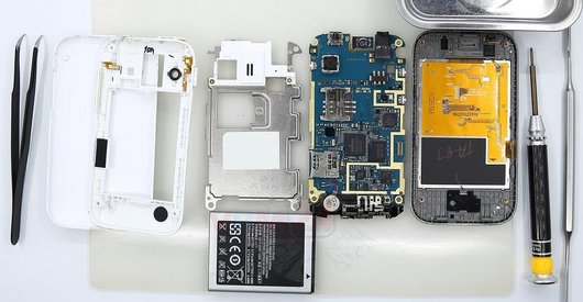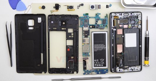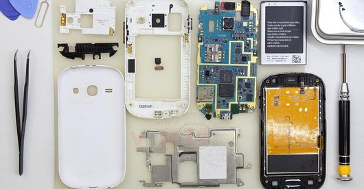

Recommended tools
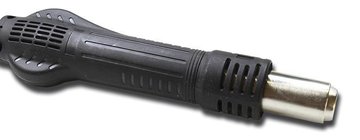
Heat gun
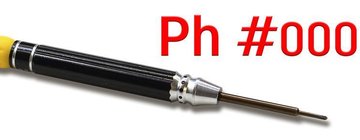
Screwdriver Phillips #000
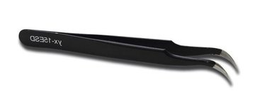
Tweezers
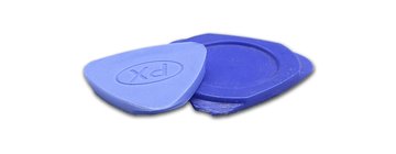
Non-metallic tool
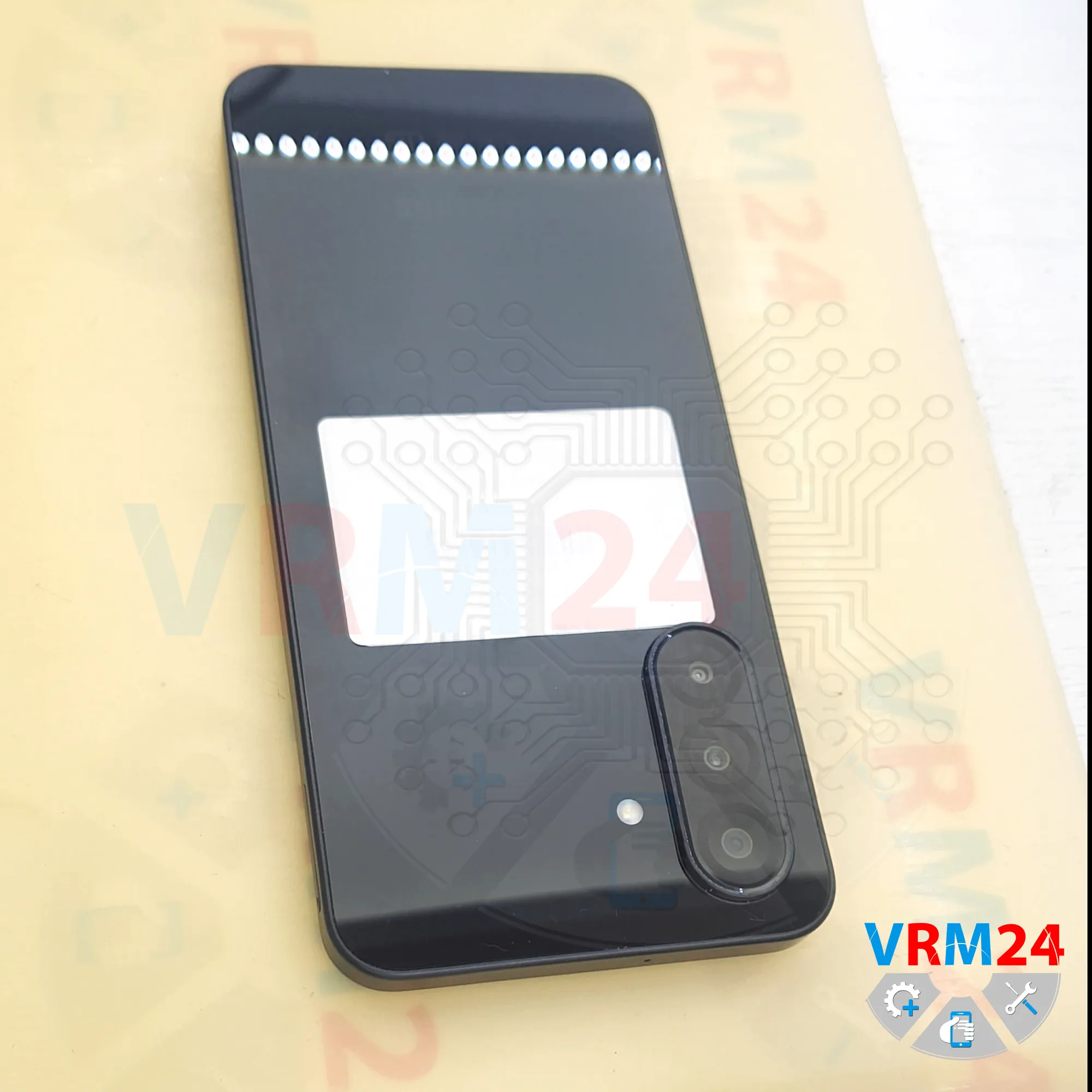
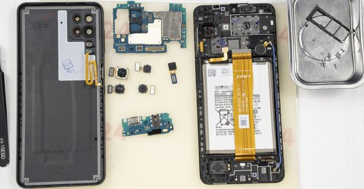
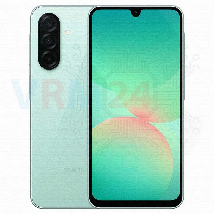
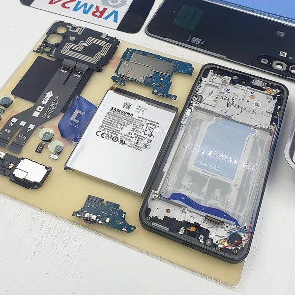
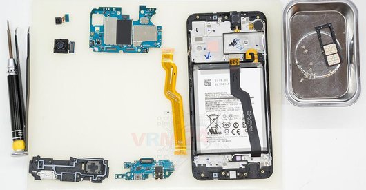
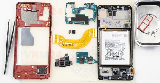
Disassembly/Repair of the mobile device Samsung Galaxy A26 SM-A268 (Samsung A26 SM-A266E, SM-A266E/DS, SM-A266E/DSN, SM-A266B, SM-A266B/DS, SM-A266B/DSN, SM-A266U, SM-A266U1, SM-A266W) with each step description and the required set of tools.
4644
Views
0
Likes
—
Share
0
Questions

Step 1.
Before disassembling!
⚠️ Before disassembling, do not forget to turn your phone off.
Step 2.
Remove the tray
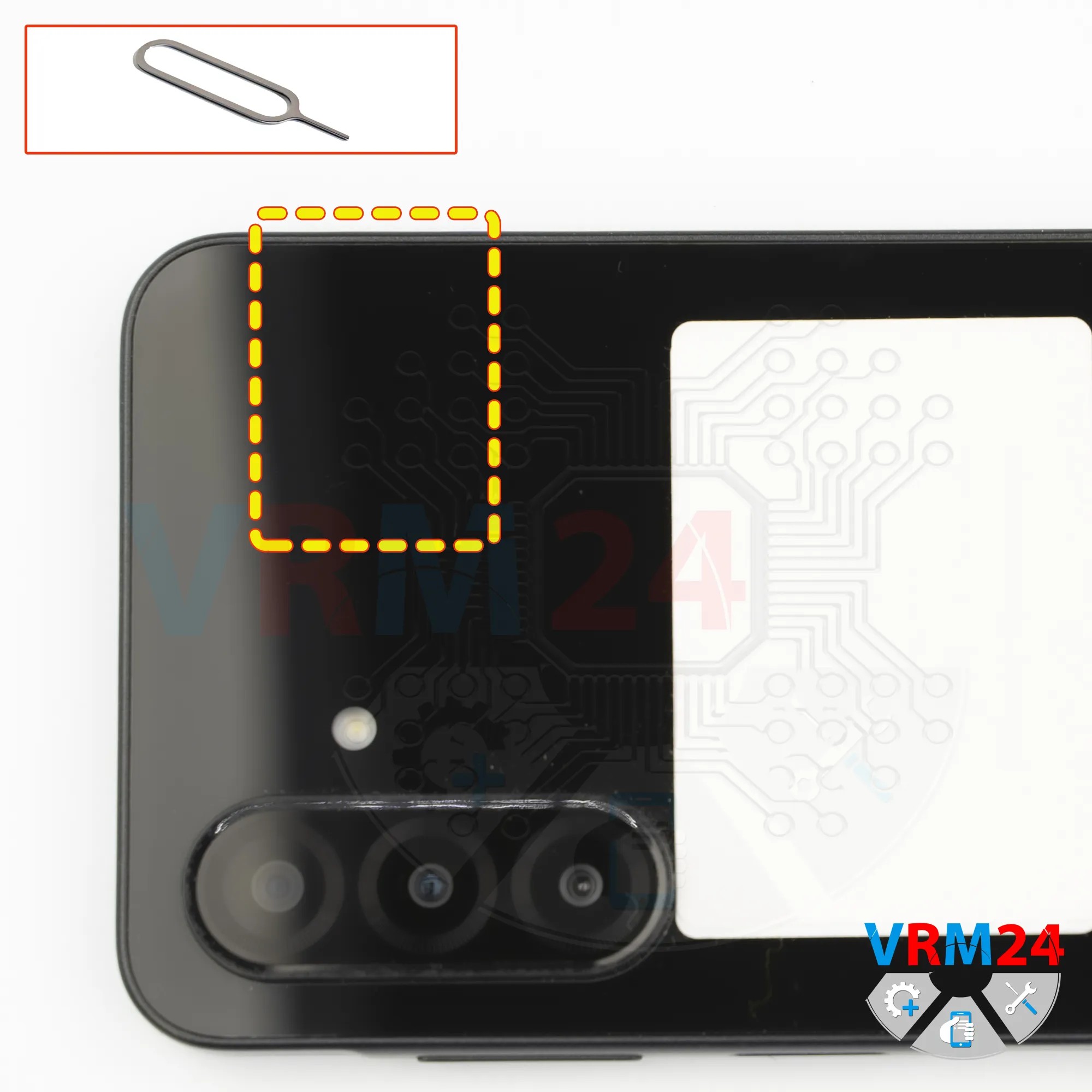
First, we need to remove the SIM card tray.
To do that, we use a SIM eject tool, insert it into the hole, and carefully push the tray out.
If the tray doesn’t come out easily, we can additionally use tweezers.
Step 3.
Open the back cover
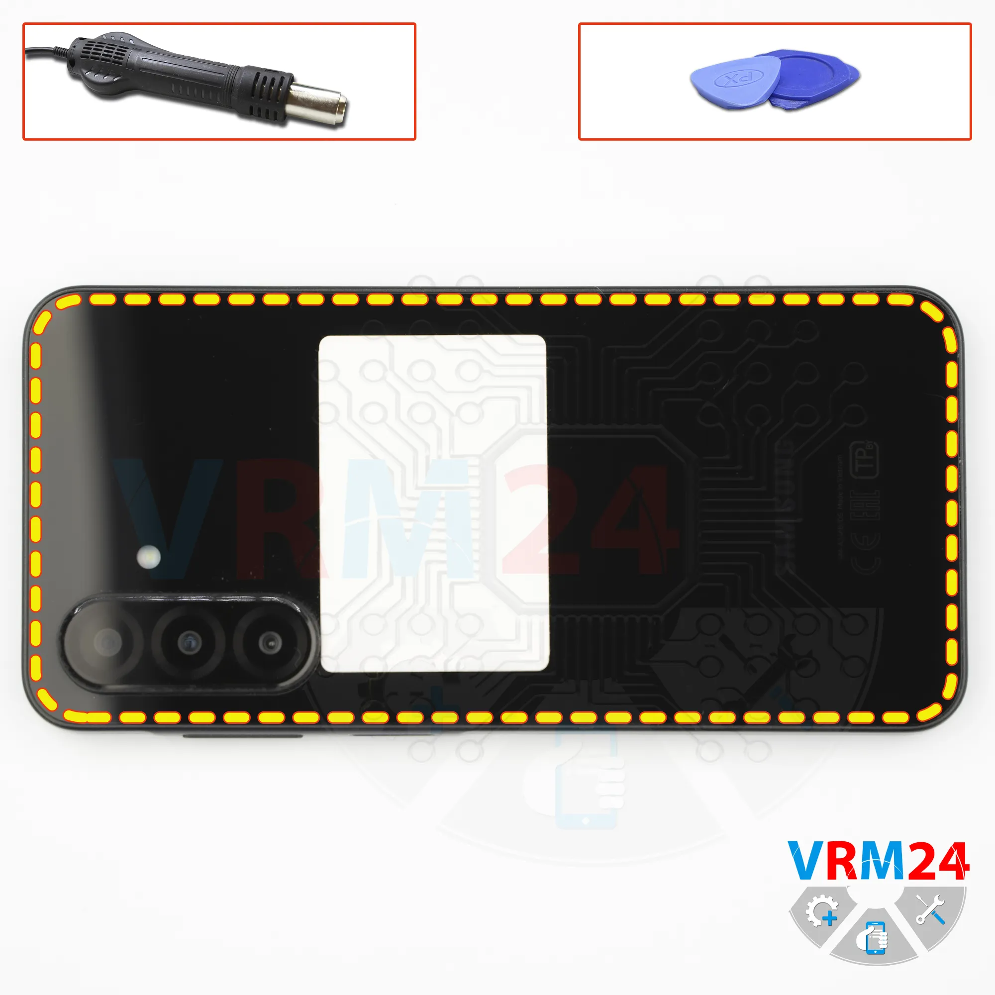
Next, we need to heat the surface of the back cover to approximately 70°C or 160°F.
We’re using a heating pad for this, but you can also use a hair dryer.
After about 10 minutes, we can proceed with removing the back cover. We use a thin plastic film, insert it into the gap between the back cover and the midframe, and carefully slide it along the edge, cutting through the adhesive.
As always, be careful around the camera area so you don’t accidentally touch or damage the lenses.
Also be careful around the side buttons, since there may be flex cables located there.
And of course, don’t insert the plastic film too deep under the back cover, since we don’t know what components are positioned there.
Step 4.
Unscrew the screws
After that, it’s best to cover the camera lenses. We use a protective film for this.
Please note that the film should be applied not on the lenses themselves, but on the rim around them.
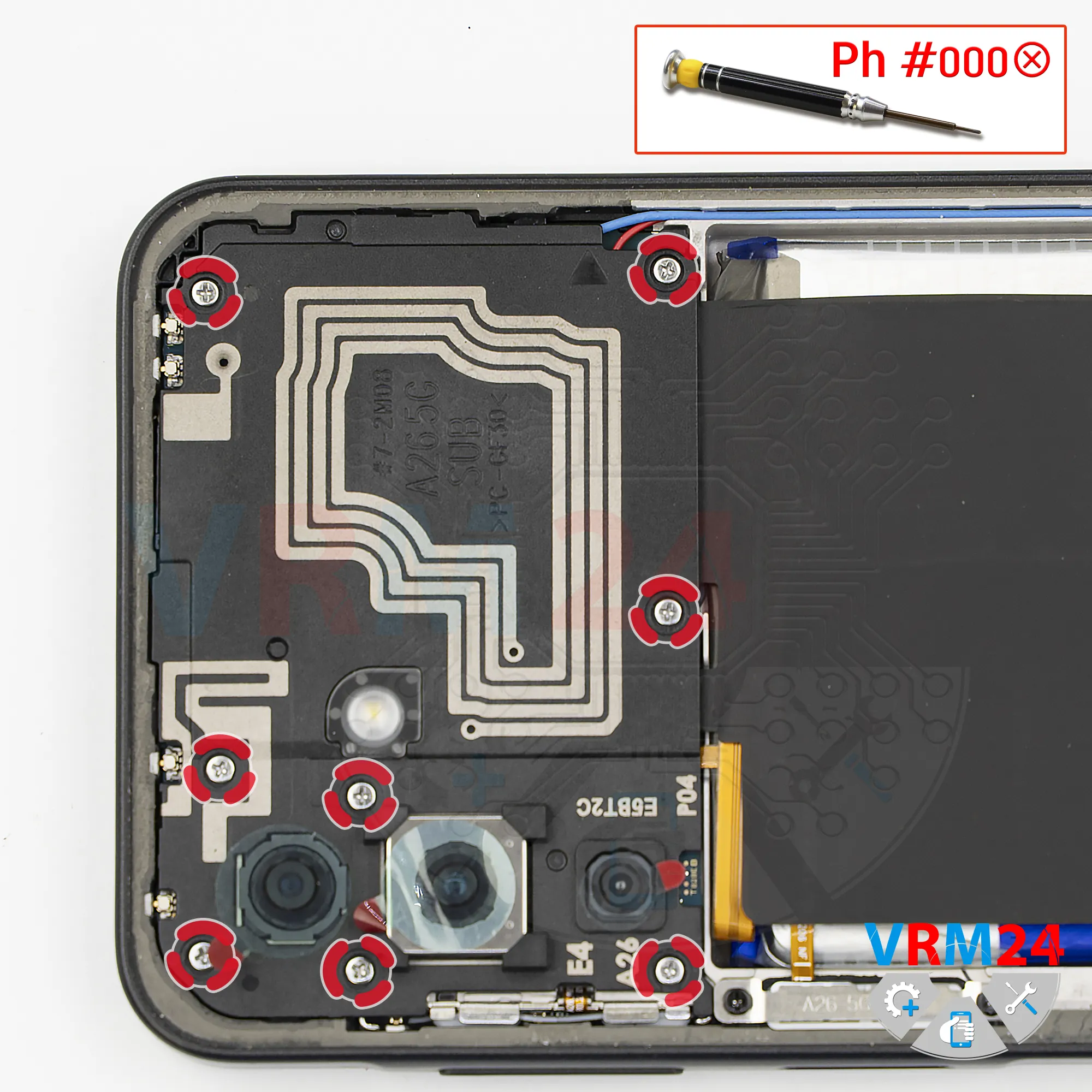
Next, we move on to removing the screws from the upper section. We use a 1.5 mm Phillips screwdriver or a Phillips #000.
If the screws are difficult to remove, we can use a magnetizer. If they’re hard to pick up, we can also use tweezers.
Step 5.
Open the cover
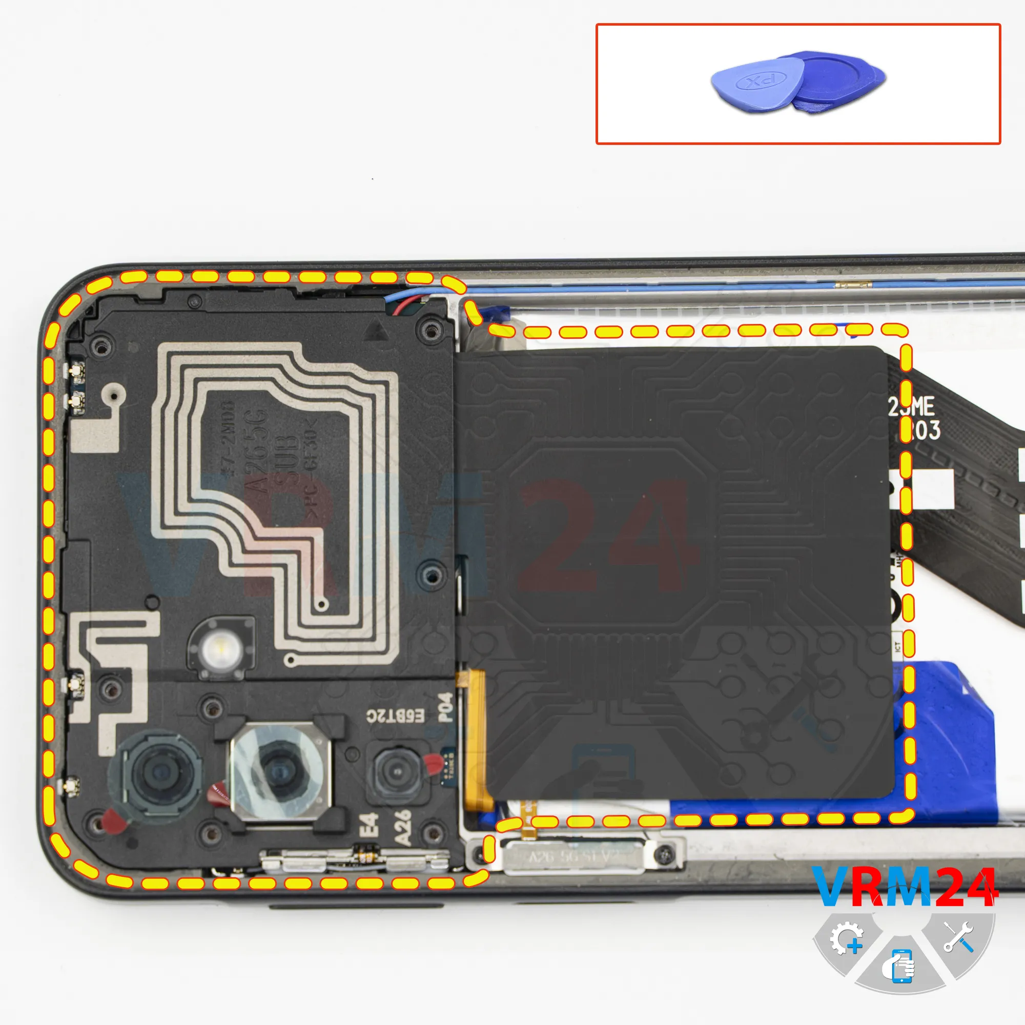
Then we need to remove the cover with the antenna traces. Carefully lift it by the edge.
It’s better not to use a metal tool to avoid shorting anything on the motherboard.
Step 6.
Disconnect the battery connector
We also disconnect the battery connector using a non-metal tool.
ℹ️ The Samsung Galaxy A26 SM-A268 uses a EB-BA166ABY rechargeable battery with a capacity of 4860 mAh.
Step 7.
Unscrew the screws
Next, we move to the lower section. In the lower part, we also remove the screws.
It looks like all the screws are the same; however, it’s better to keep the screws from the lower section separate from the previous ones.
Step 8.
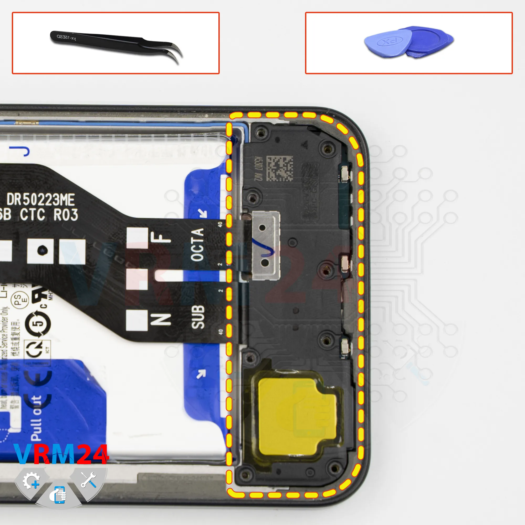
Remove the loudspeaker
Now we can remove the cover. Carefully lift it at the correct point and remove the cover with the loudspeaker.
Step 9.
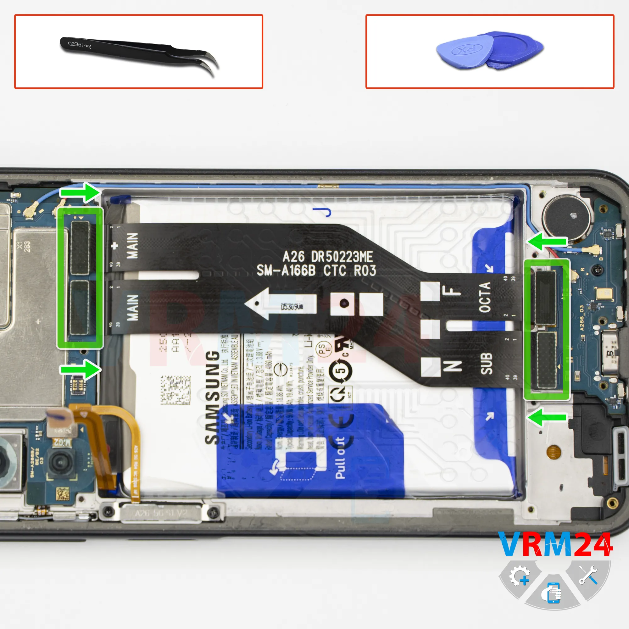
Remove the interconnect cable
Then we need to disconnect the connectors.
We disconnect the interconnect flex cable connectors on the sub-board. We disconnect the interconnect flex cable connectors on the motherboard.
Please note that there is an arrow on the flex cable indicating the direction toward the motherboard.
Then we move the cable aside.
Step 10.
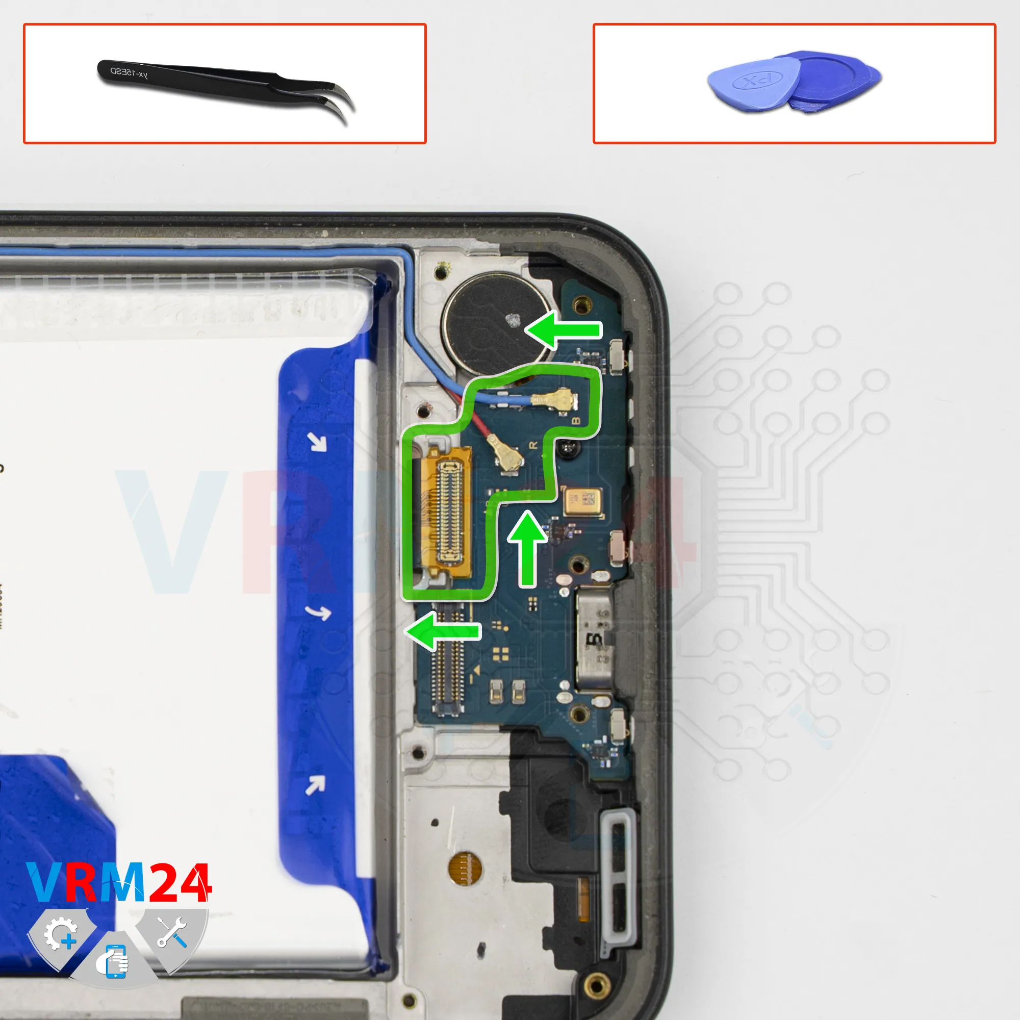
Disconnect the connectors
After that, we disconnect the two coaxial cable connectors.
Carefully release the cables themselves from the clips securing them to the sub-board.
We also need to peel off the display flex cable with its connector.
Carefully lift it at the correct point and peel it off.
Step 11.
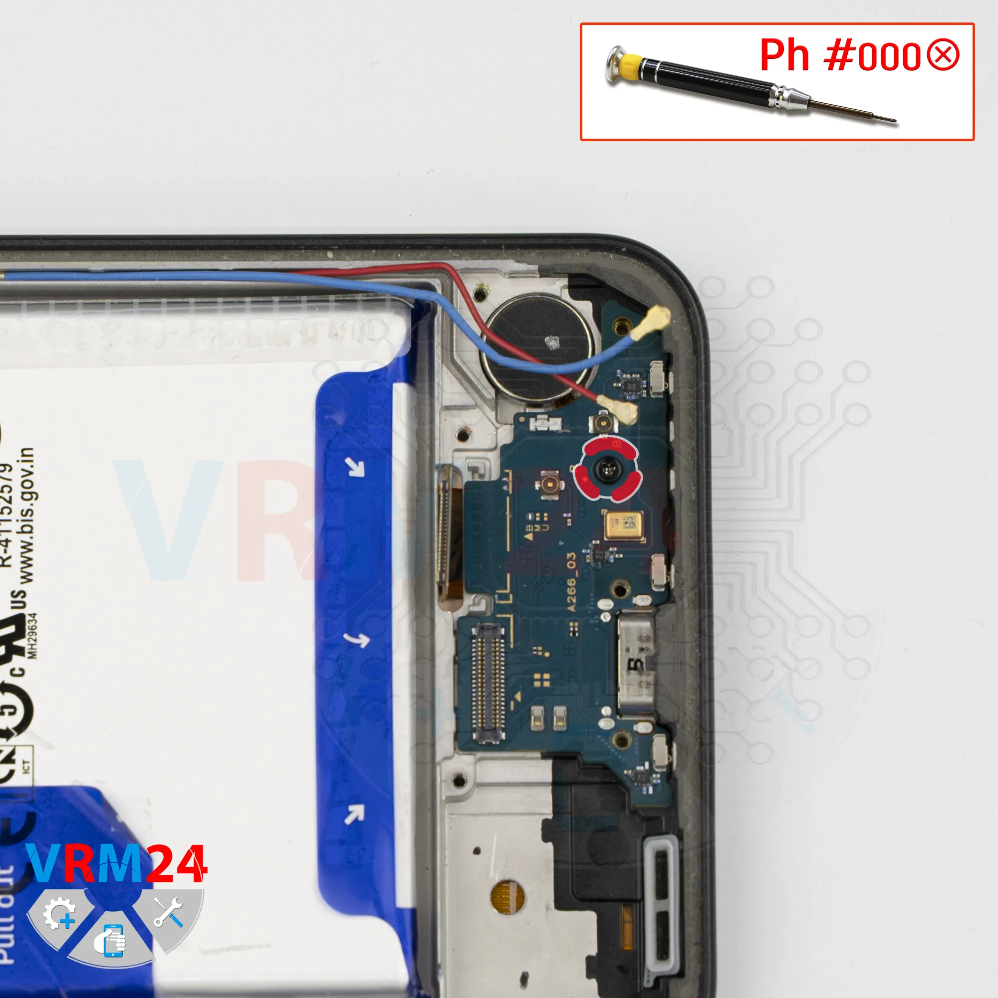
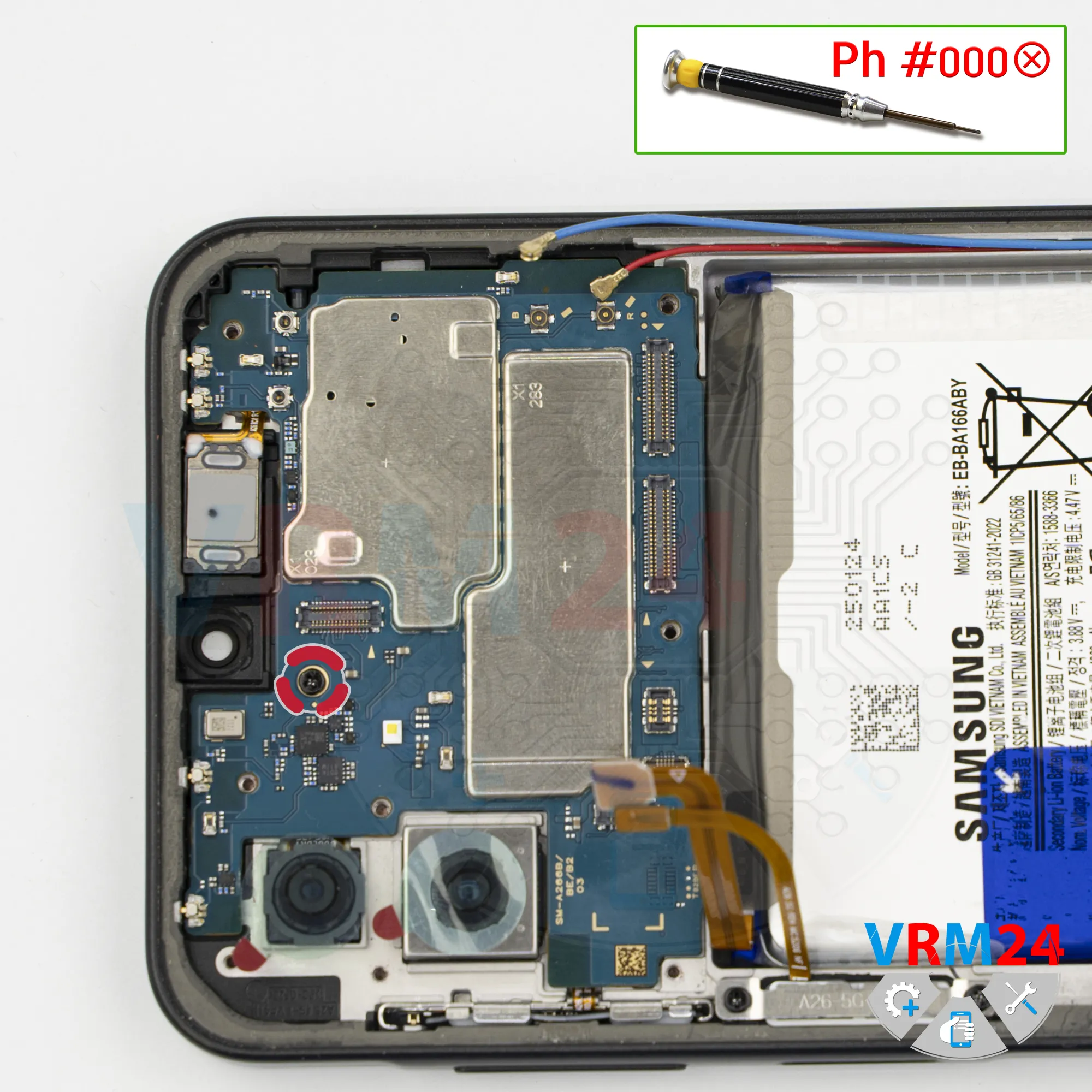
Unscrew one screw
Next, we need to remove one screw securing the sub-board.
We use the same 1.5 mm Phillips screwdriver or Phillips #000.
By the way, this screw is different from the previous ones, so it’s better to keep it separate.
Step 12.
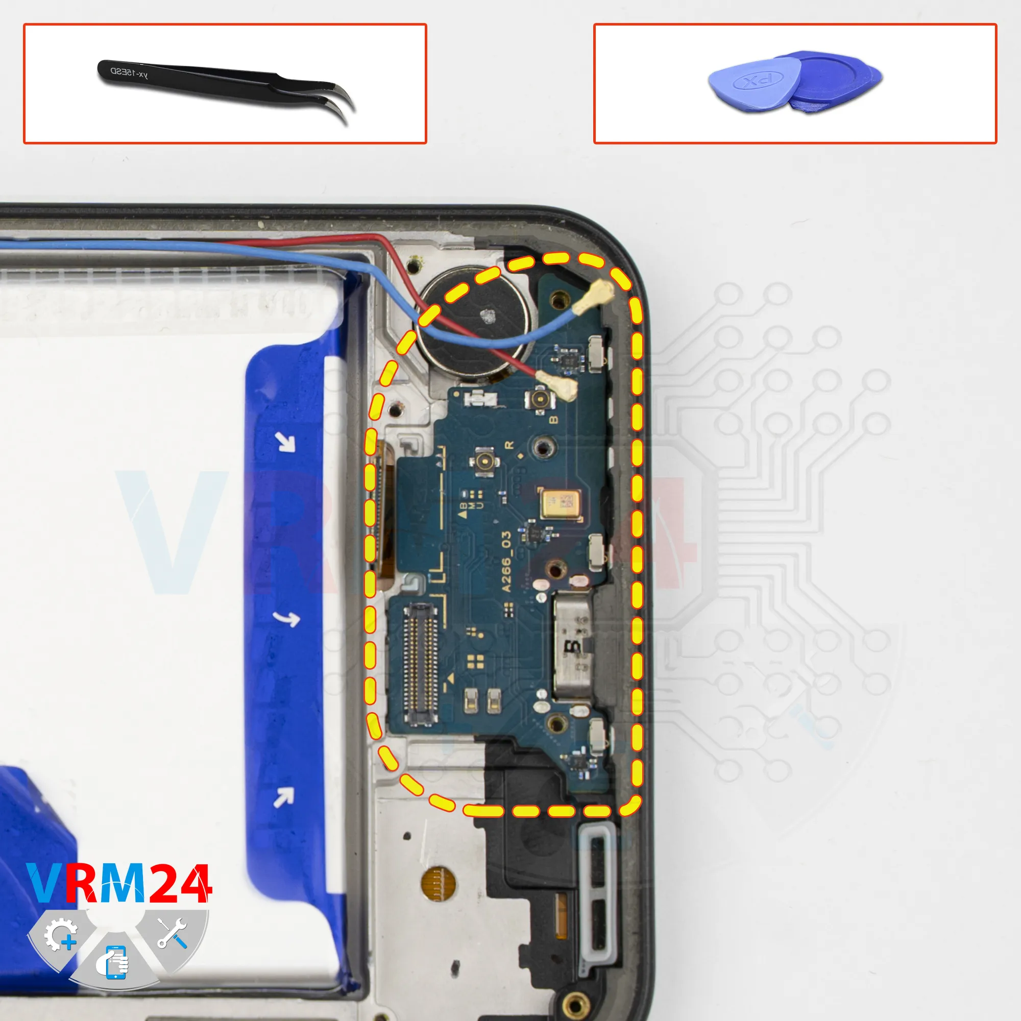
Remove the sub-board
Now we can remove the sub-board.
Carefully lift it at the edge, in the correct spot, raise it up, and take out the sub-board.
The sub-board contains the charging port, the microphone, and other components on the reverse side.
Step 13.
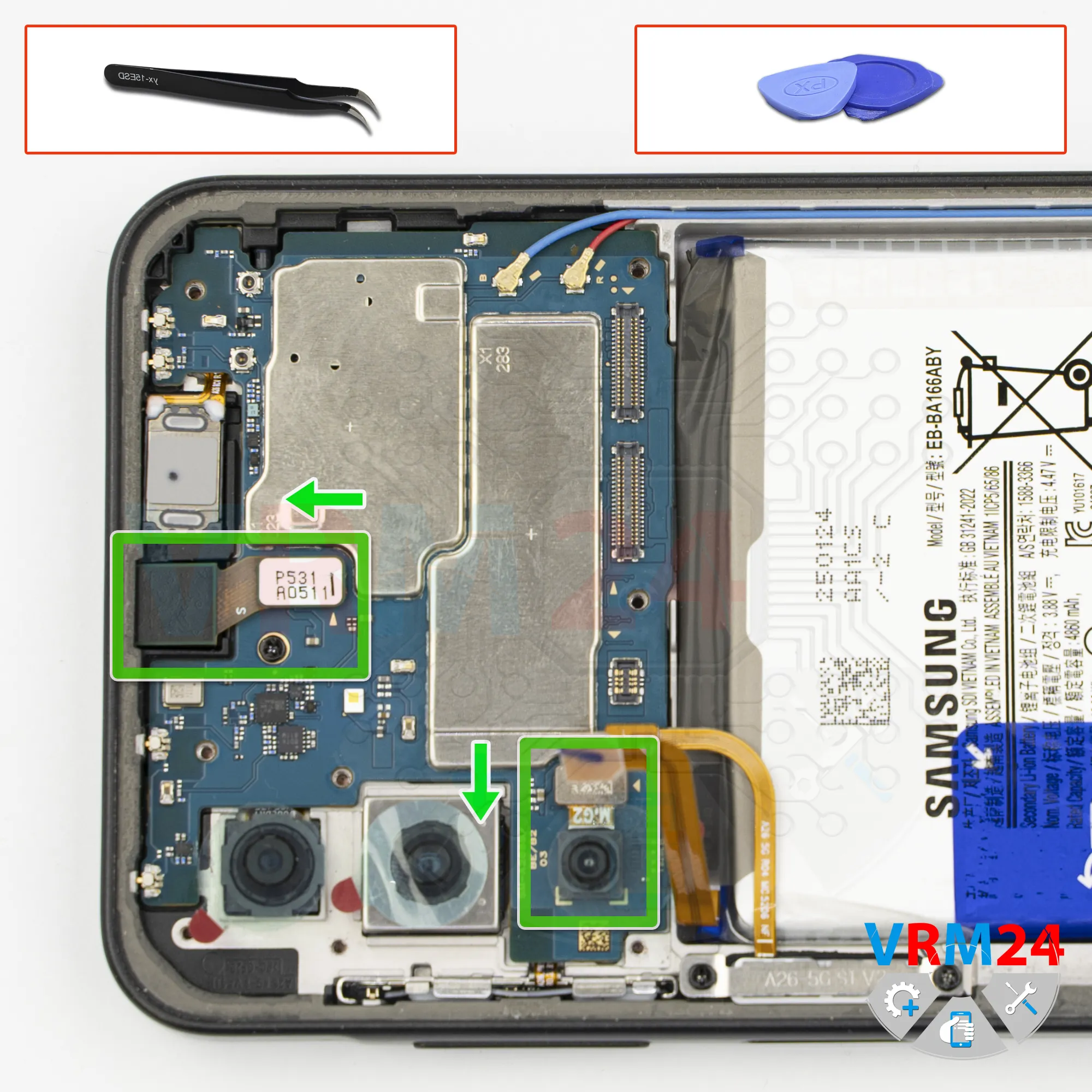
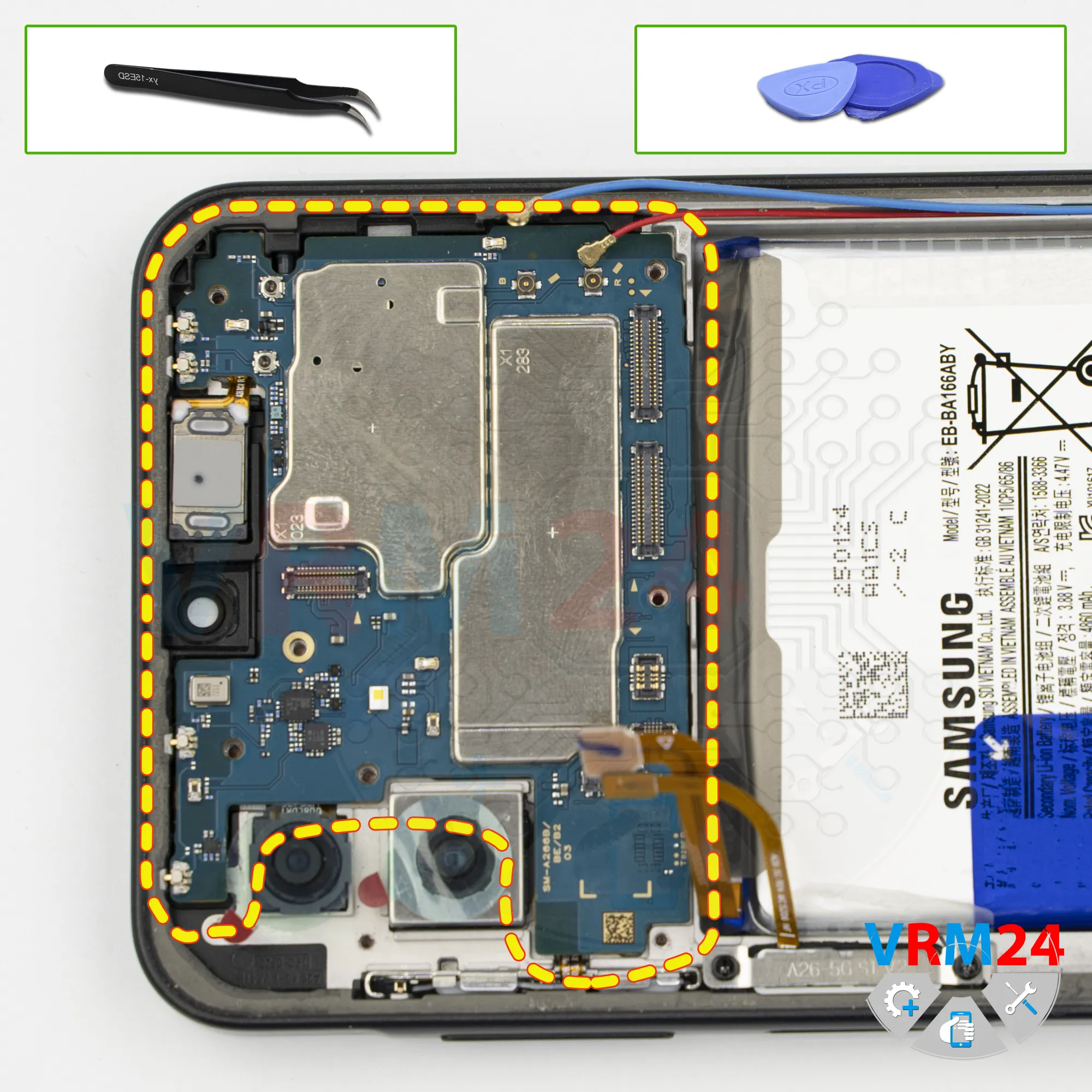
Remove the cameras
Now we move on to the motherboard.
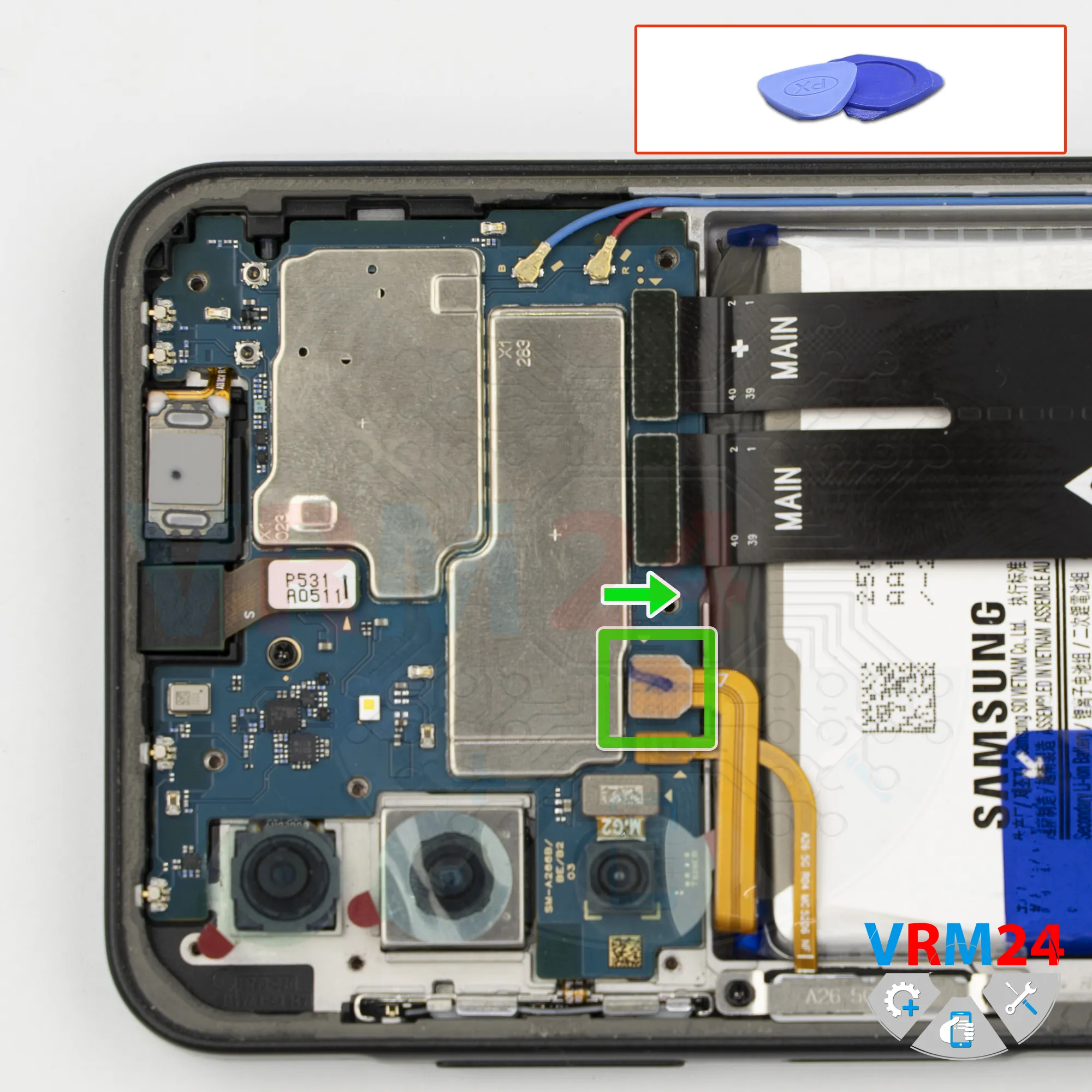
On the motherboard, we disconnect one rear camera that can be removed.
We can also disconnect the front camera.
Carefully lift it by the edge, disconnect the connector, and remove it.
It’s best to cover the camera lens to prevent dust or debris from getting on it. Set the camera aside.
Step 14.
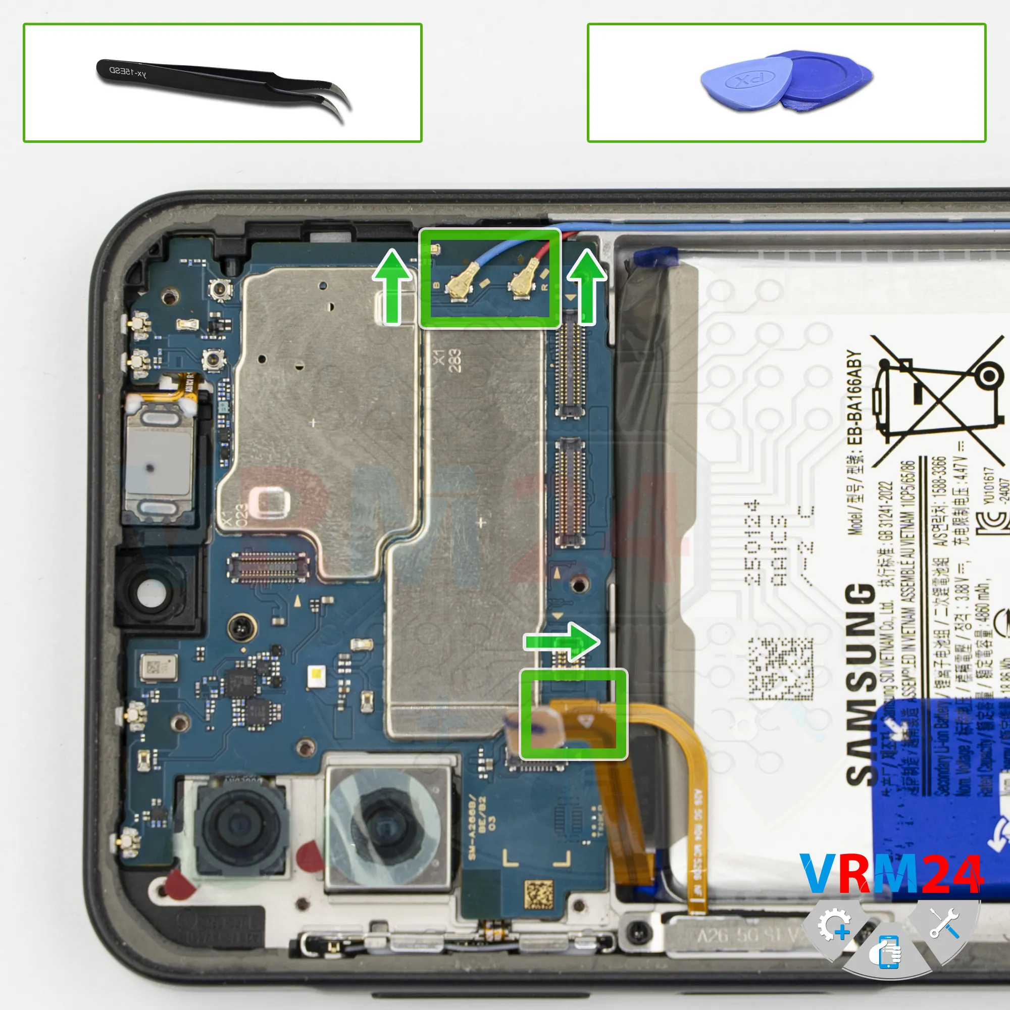
Disconnect the connectors
We also need to disconnect the coaxial cable connectors.
And we can also disconnect the connector for the fingerprint sensor as well.
Step 15.
Unscrew one screw
Next, we need to remove one screw that secures the motherboard. Carefully remove this screw.
Please note that this screw is different from the ones in the upper section, so it’s better to keep it separate.
Step 16.
Remove the motherboard
Now we remove the motherboard.
⚠️ Do not bend the circuit board when removing it or push tools under it. Unbeknownst to yourself, you can damage components or cables from the inside.
Step 17.
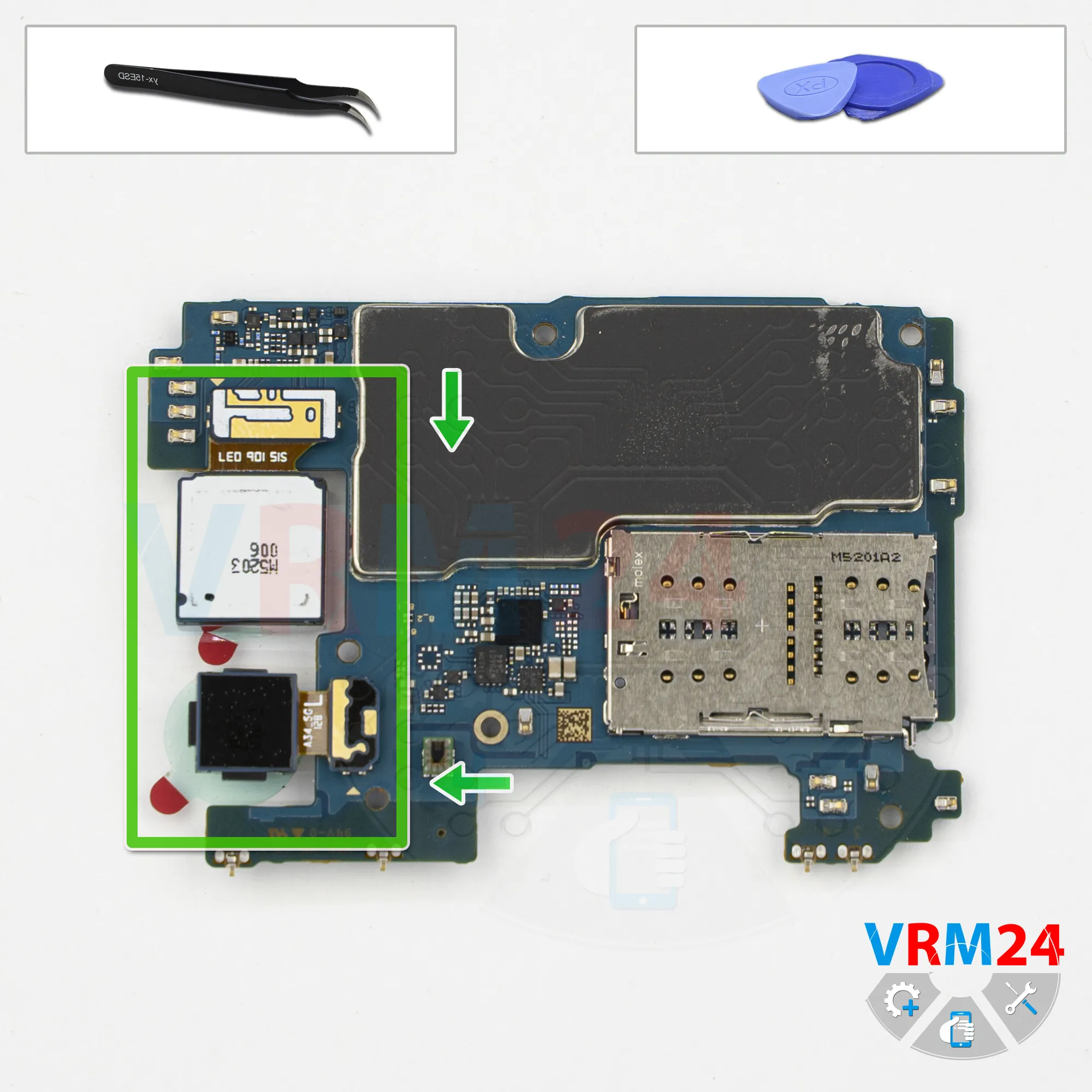
Remove the cameras
We flip the motherboard over, disconnect the rear cameras, and set them aside.
Step 18.
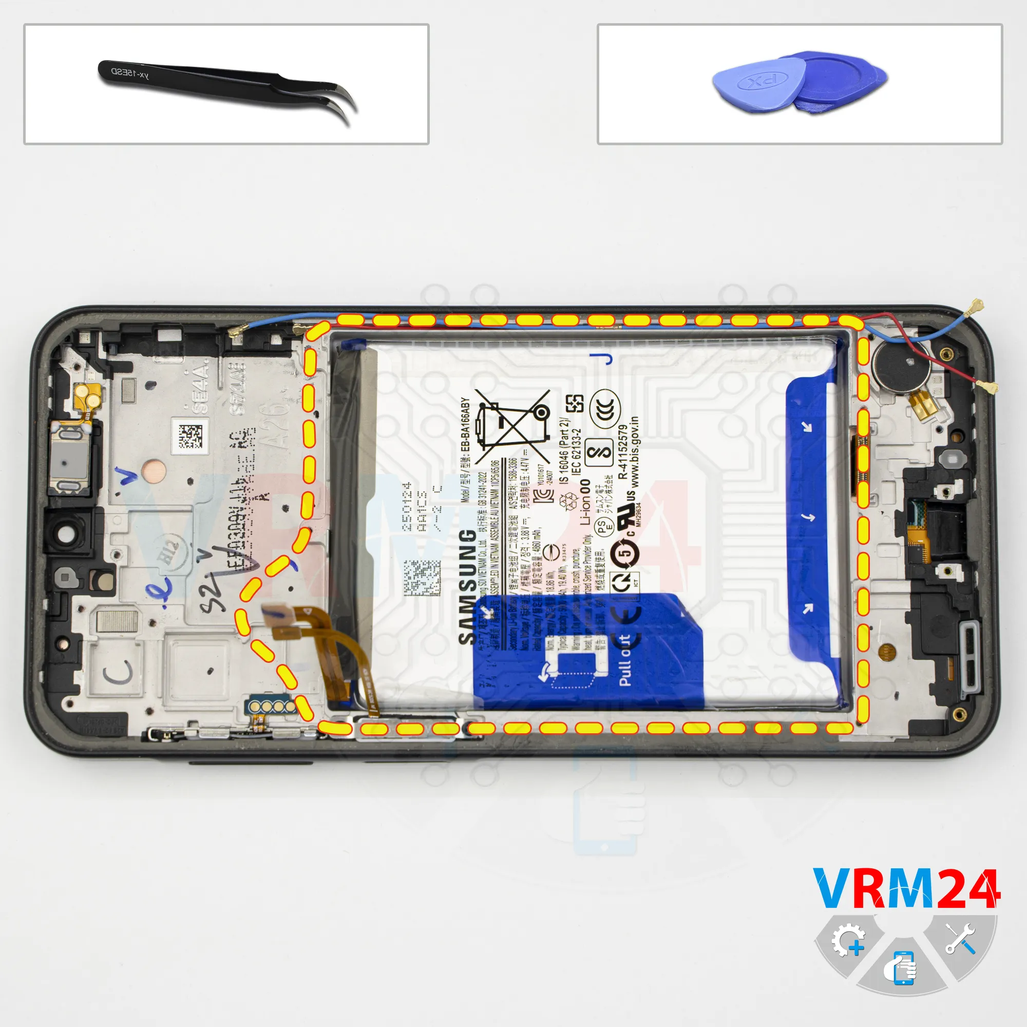
Remove the battery
Finally, we move on to removing the battery.
We need to peel back the two blue pull tabs, remove the white transparent film, and pull the tab in the center to detach the battery.

If you have a question, ask us, and we will try to answer in as much detail as possible. If this article was helpful for you, please rate it.

4644
Views
0
Likes
—
Share
0
Questions
Related Instructions
Related Reviews
Related Blog
Top instructions
Check our
Top Samsung instructions most liked by readers
New instructions
Check our
New Samsung brand instructions on vrm24.com