

⚠️️ Before disassembling, do not forget to turn your phone off.
Teardown difficulty:
Moderate
Moderate
Recommended tools


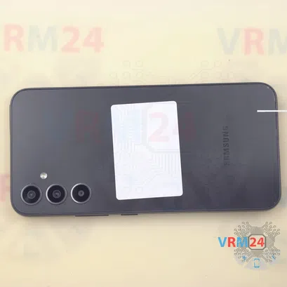
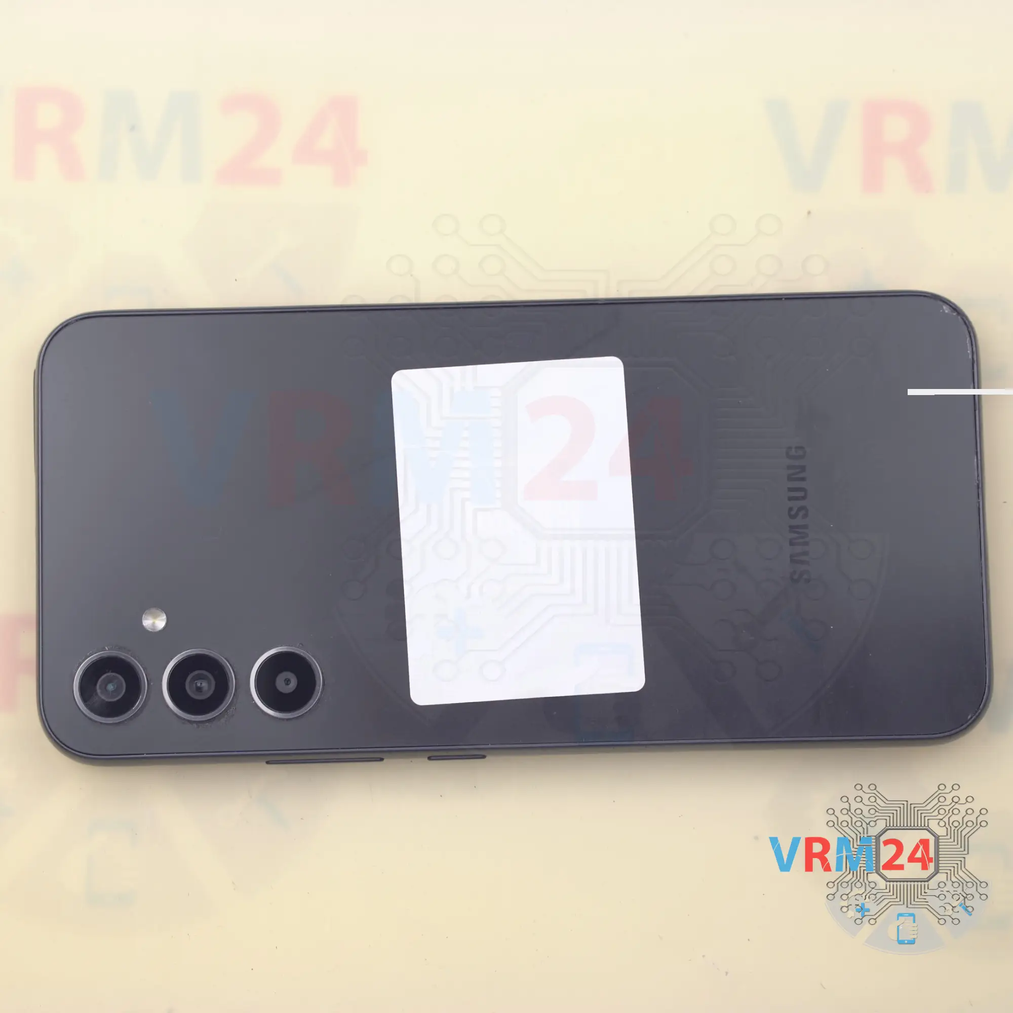
Disassembly/Repair of the mobile device Samsung Galaxy A34 SM-A346 (Samsung Galaxy A34 SM-A346E, SM-A346B, SM-A346B/DS, SM-A346B/DSN, SM-A346E/DS, SM-A346E/DSN, SM-A346M, SM-A346M/N, SM-A346M/DSN, SM-A3460) with each step description and the required set of tools.


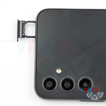

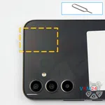
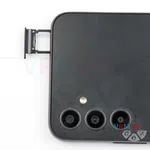
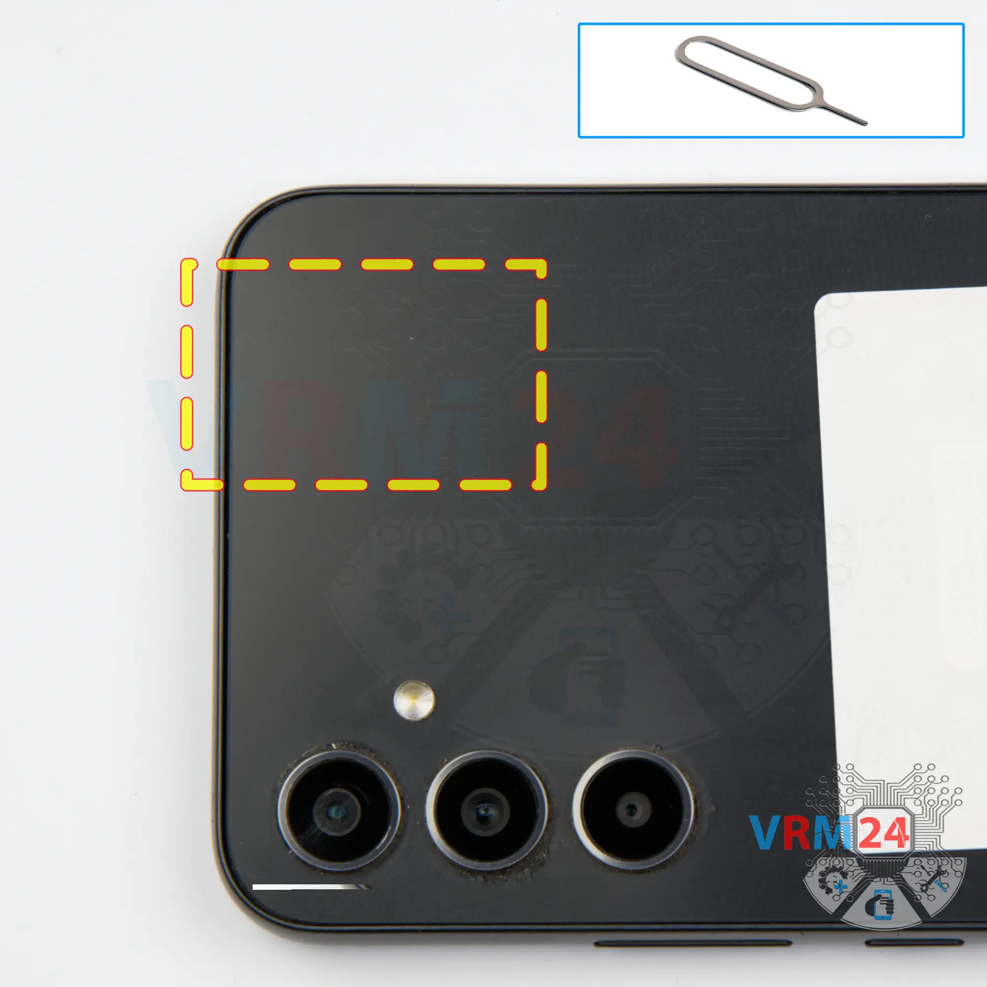
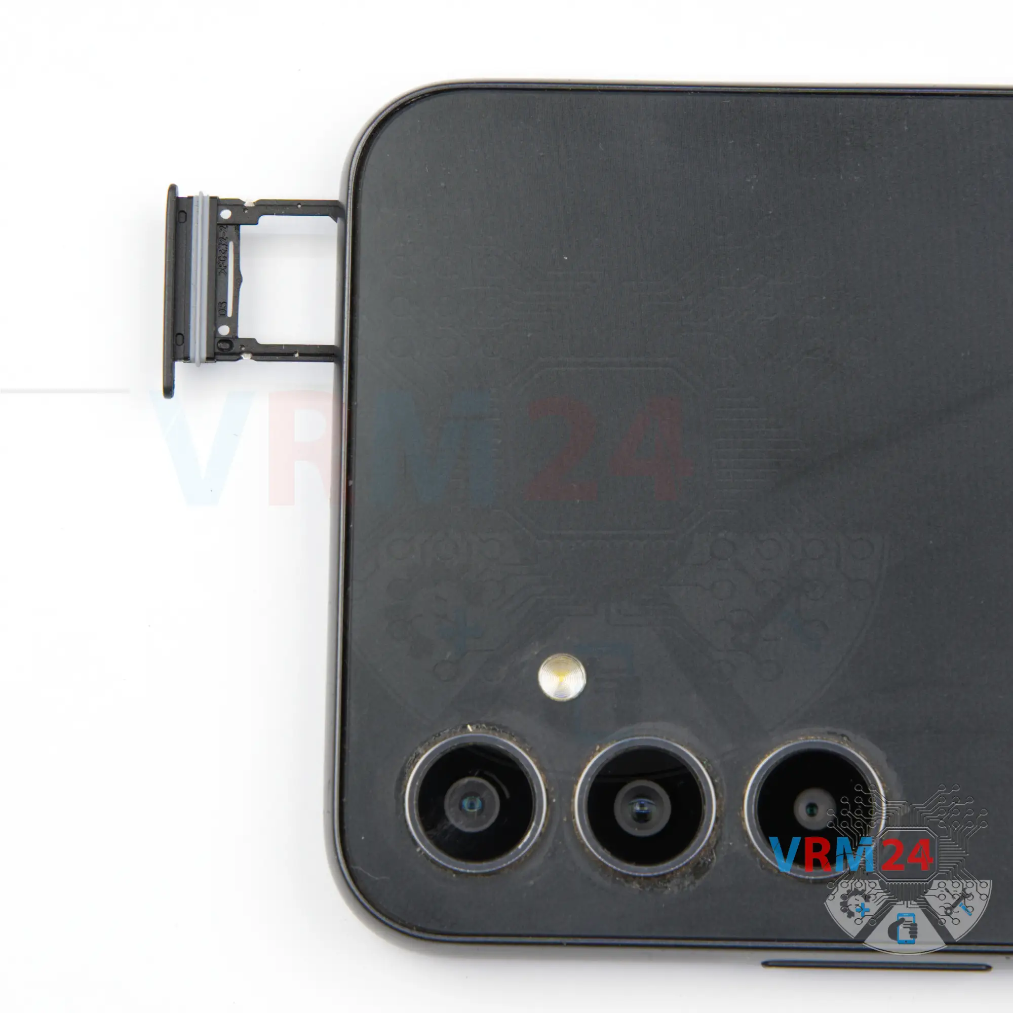
Step 2. Remove the tray
First of all, we need to remove the card tray. To do this, we use a special tool, insert it into the hole and carefully push out the combined tray for sim cards and memory cards.
⚠️️ Pay attention! Do not press too hard. It may break the tray eject mechanism.
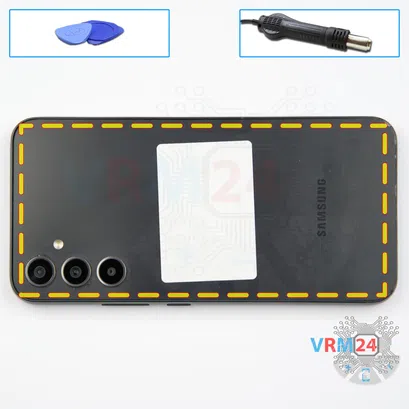


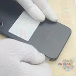
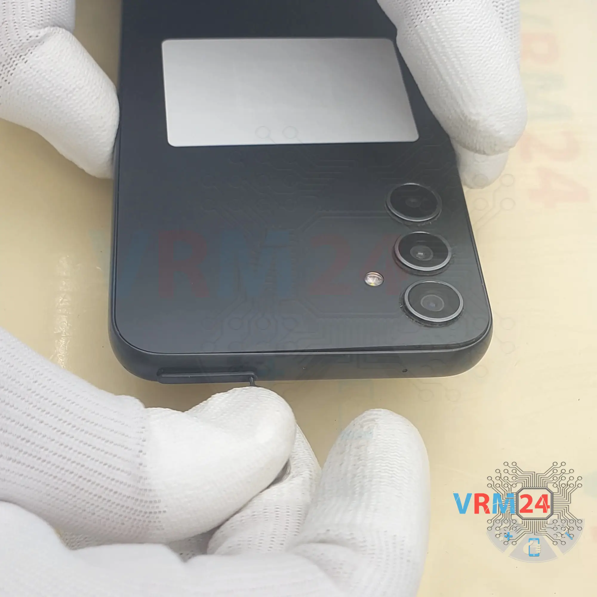
Step 3. Open the back cover
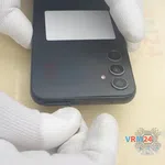
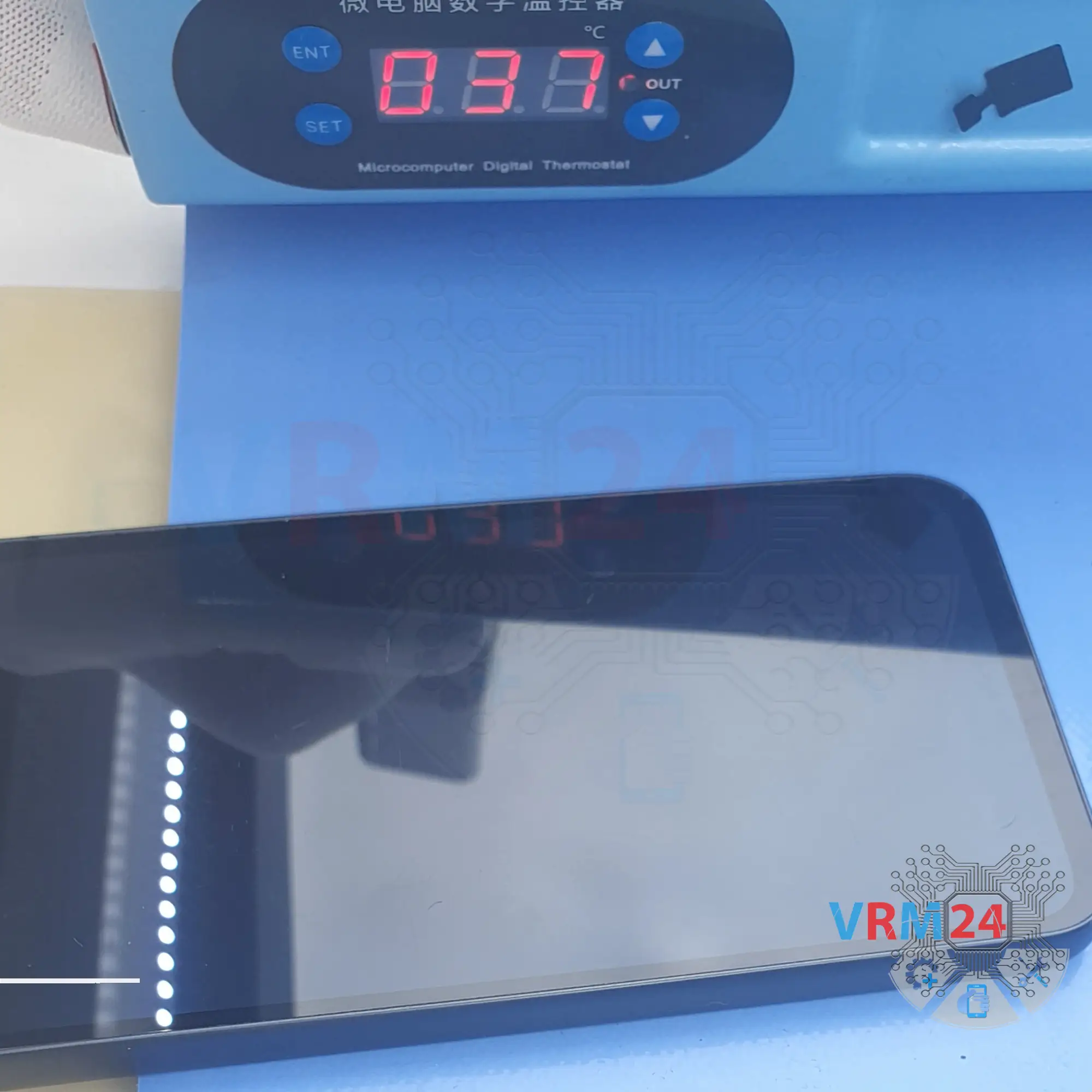
After that, we need to heat the surface of the back cover to a temperature of approximately 70 ° C or 160° F. For this we use a heating mat, you can use a hair dryer.
And after 5 to 7 minutes, we can move on to detach the back cover.
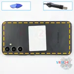
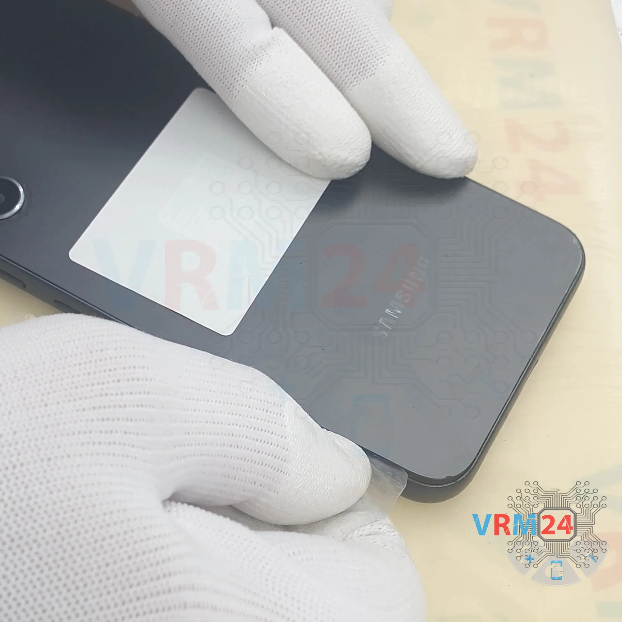
To remove the back cover, we use a thin plastic film. This film can be a film from a new display or a film from a stationery store. Carefully insert it into the gap between the back cover and the middle cover. Carefully run the film along the side, cutting off the adhesive backing.
We need to be careful as we have the back cover slightly recessed into the middle cover. We need to be careful in the camera area. We should be careful around the side buttons so that we don't accidentally damage anything.
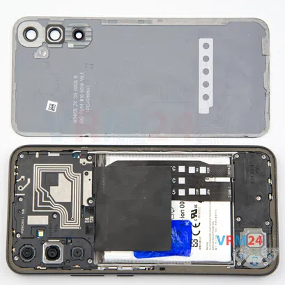
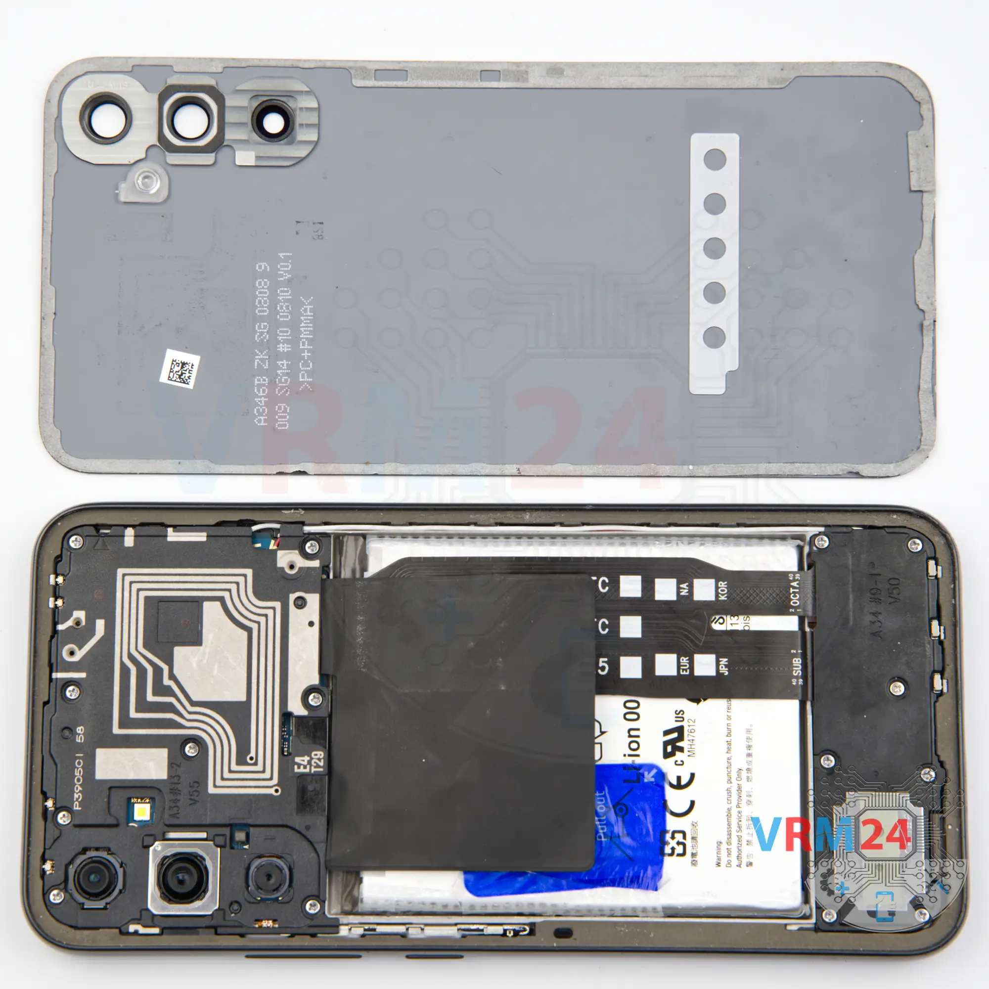
On the back cover, as we can see, we have nothing presented.
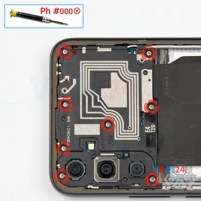
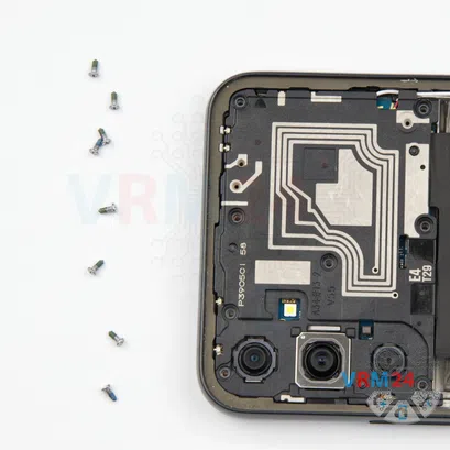

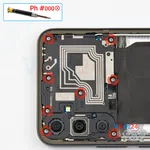
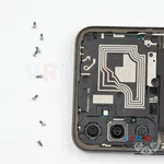
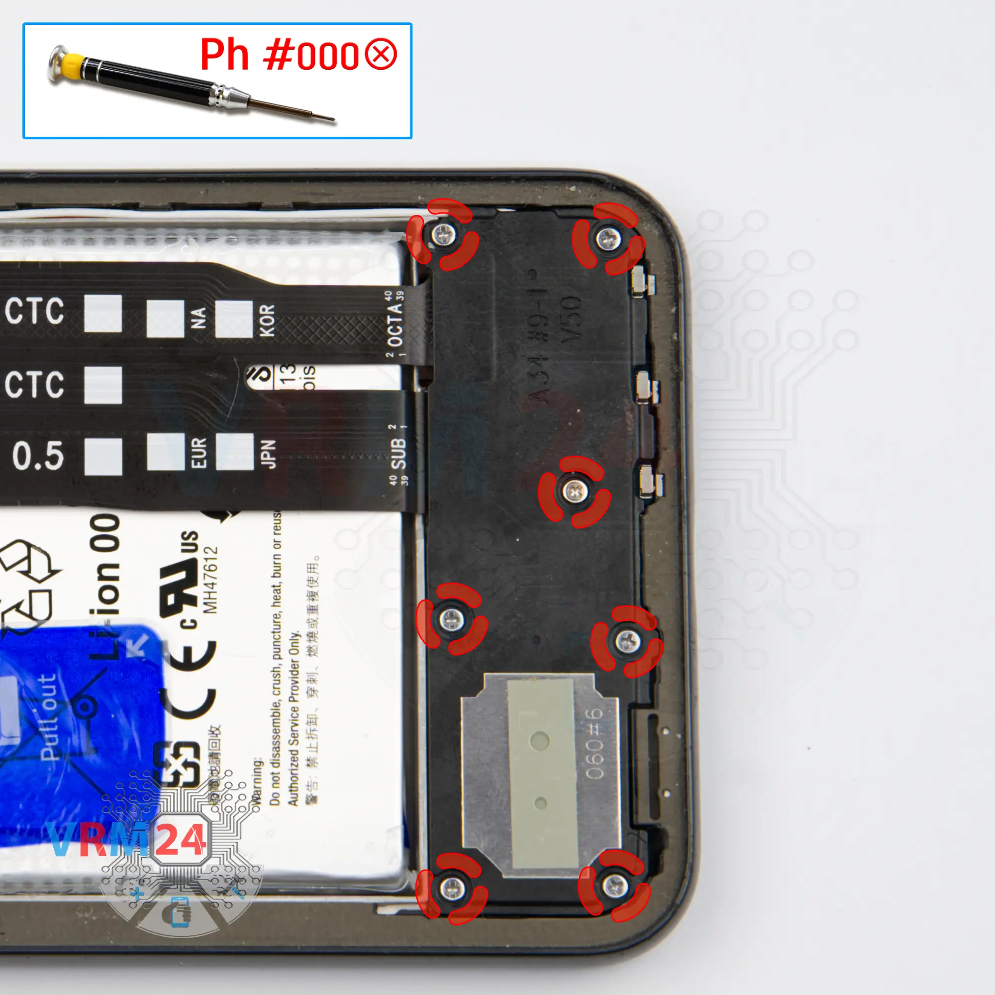
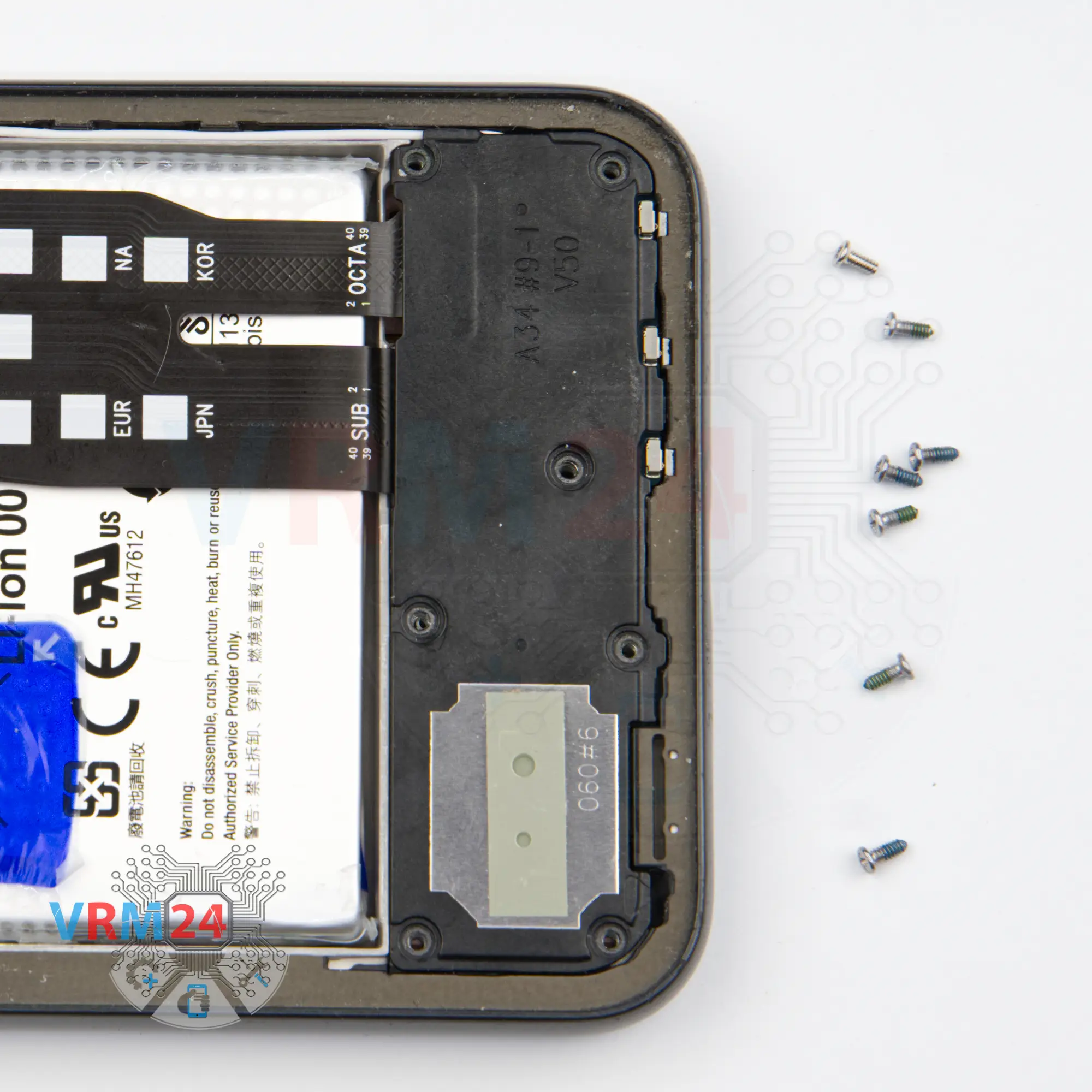
Step 4. Unscrew the screws
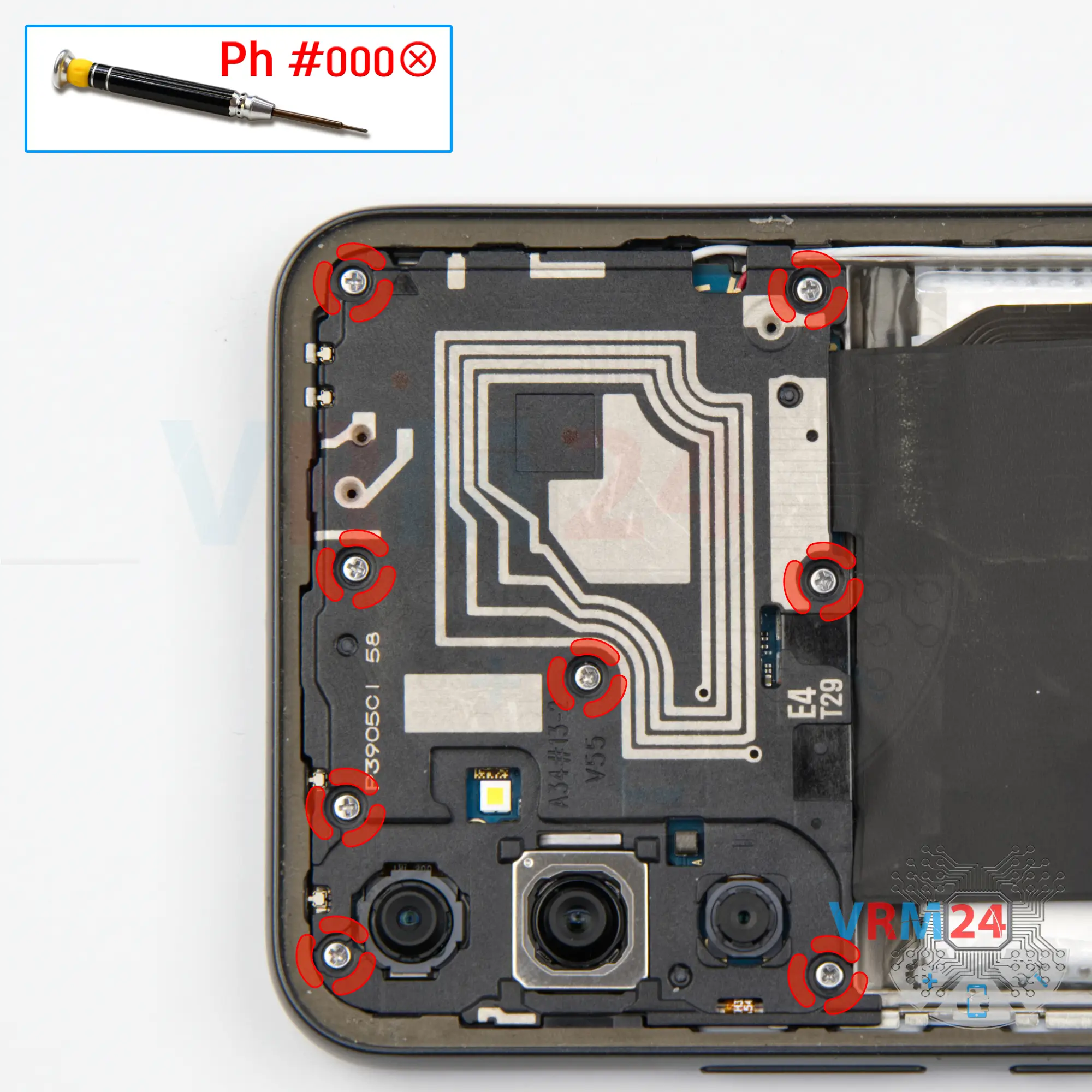
After that we need to unscrew the eight screws on the top. For this, we use a 1.5mm Phillips screwdriver or Philips #000.
It looks like all the screws are the same, but we nevertheless recommend placing them on a special surface in a certain order, just in case.
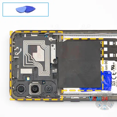


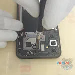
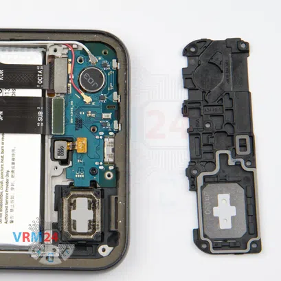
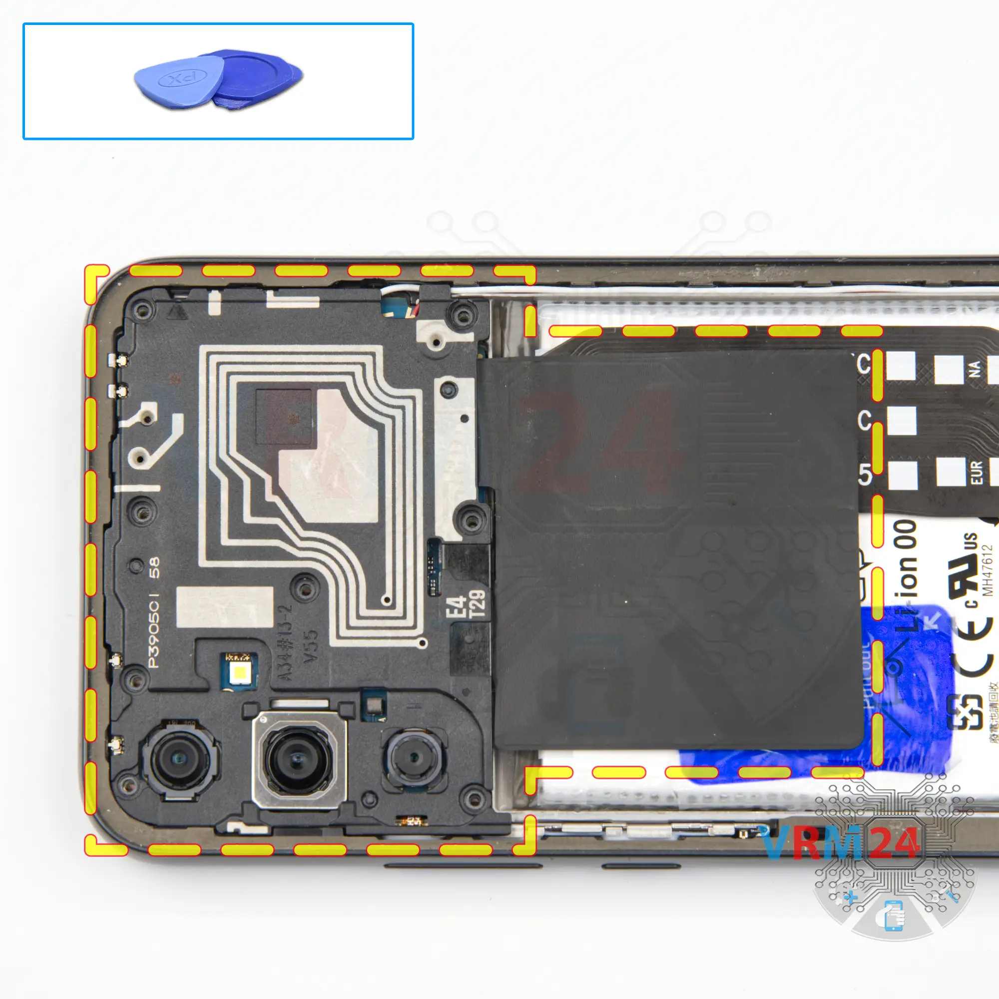
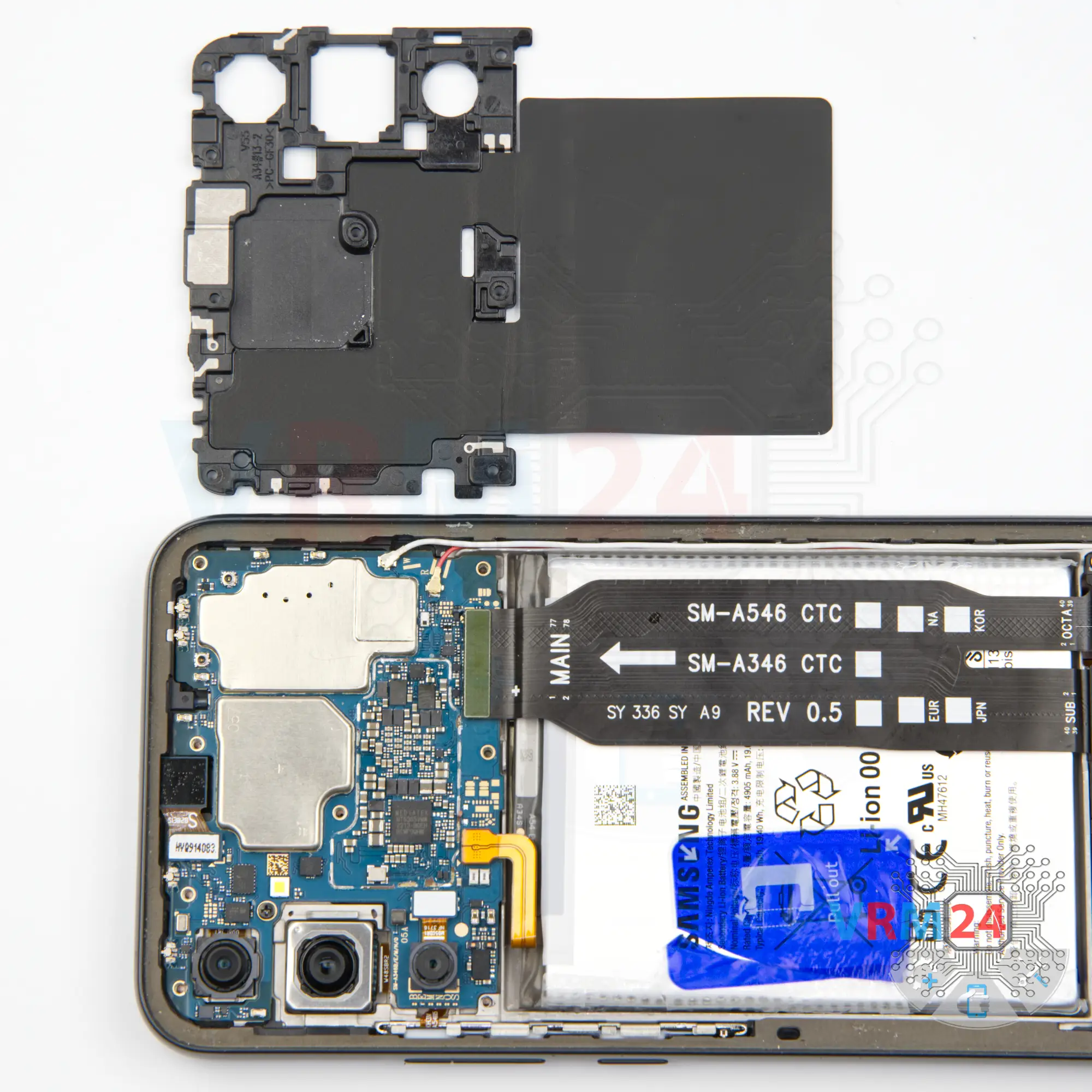
Step 5. Open the cover
Then we need to detach the cover hiding the motherboard, the cover with antenna transmission lines.
Carefully using a non-metal tool, we hook it in the right place and of course, it is really important for us to find this right place and detach the cover.


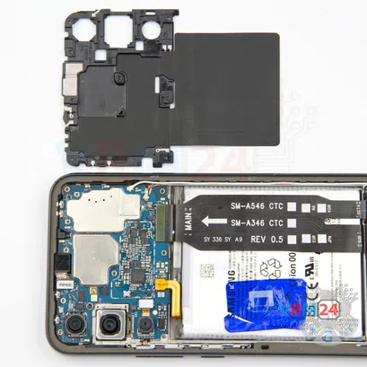
Step 6. Disconnect the battery connector
Disconnect the battery connector as soon as you can. Use a non-metallic or plastic tool to avoid any damage.
ℹ️️ The Samsung Galaxy A34 SM-A346 model has a battery EB-BA546ABY with a capacity of 5000 mAh (also known as a rechargeable battery).

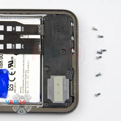


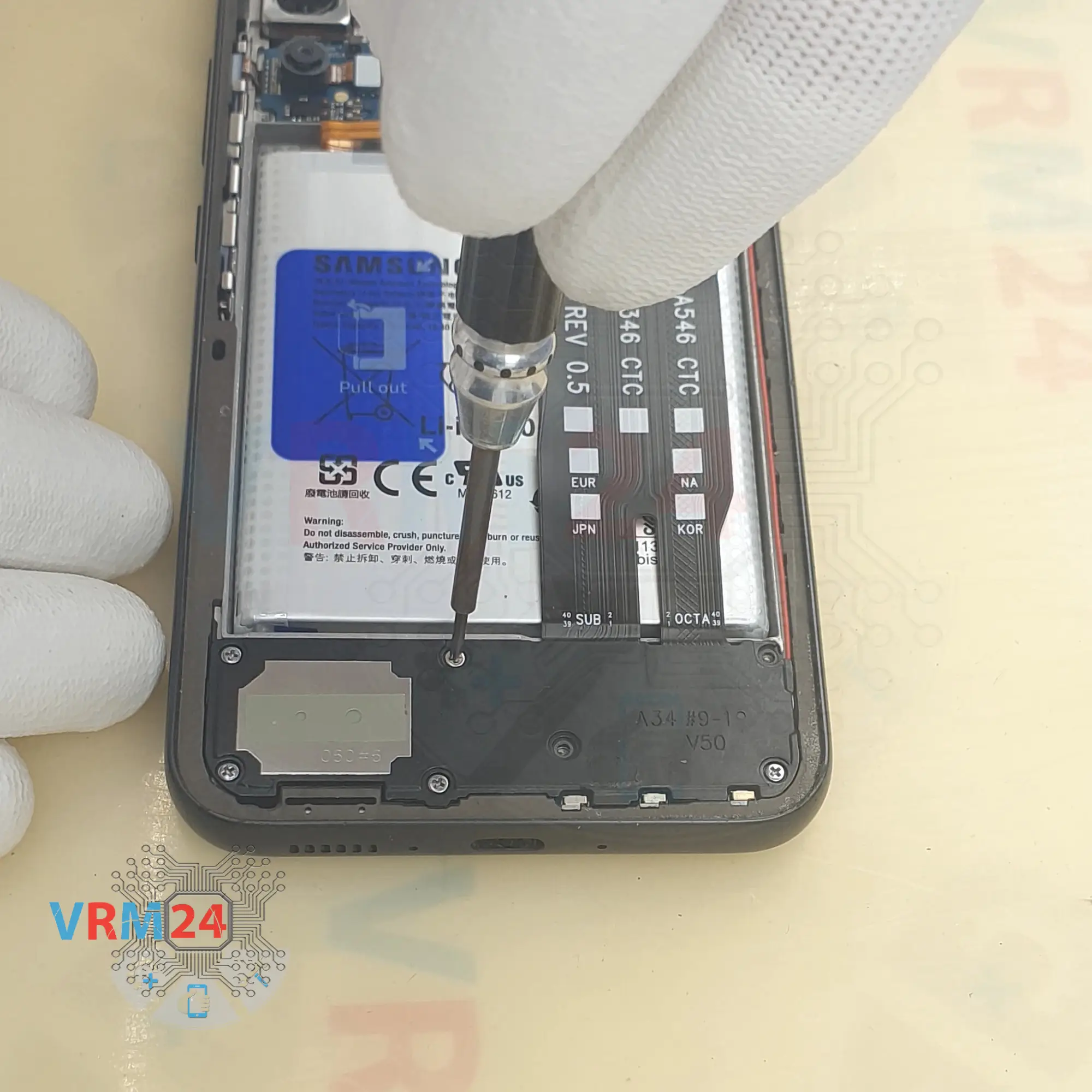
Step 7. Unscrew the screws
And we move on to unscrewing the seven screws at the bottom.
The screws at the bottom also seem to be all the same and we also recommend to place them on some special surface, just in case.
We also use a one and a half millimeter Phillips screwdriver to remove the screws.


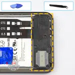
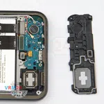

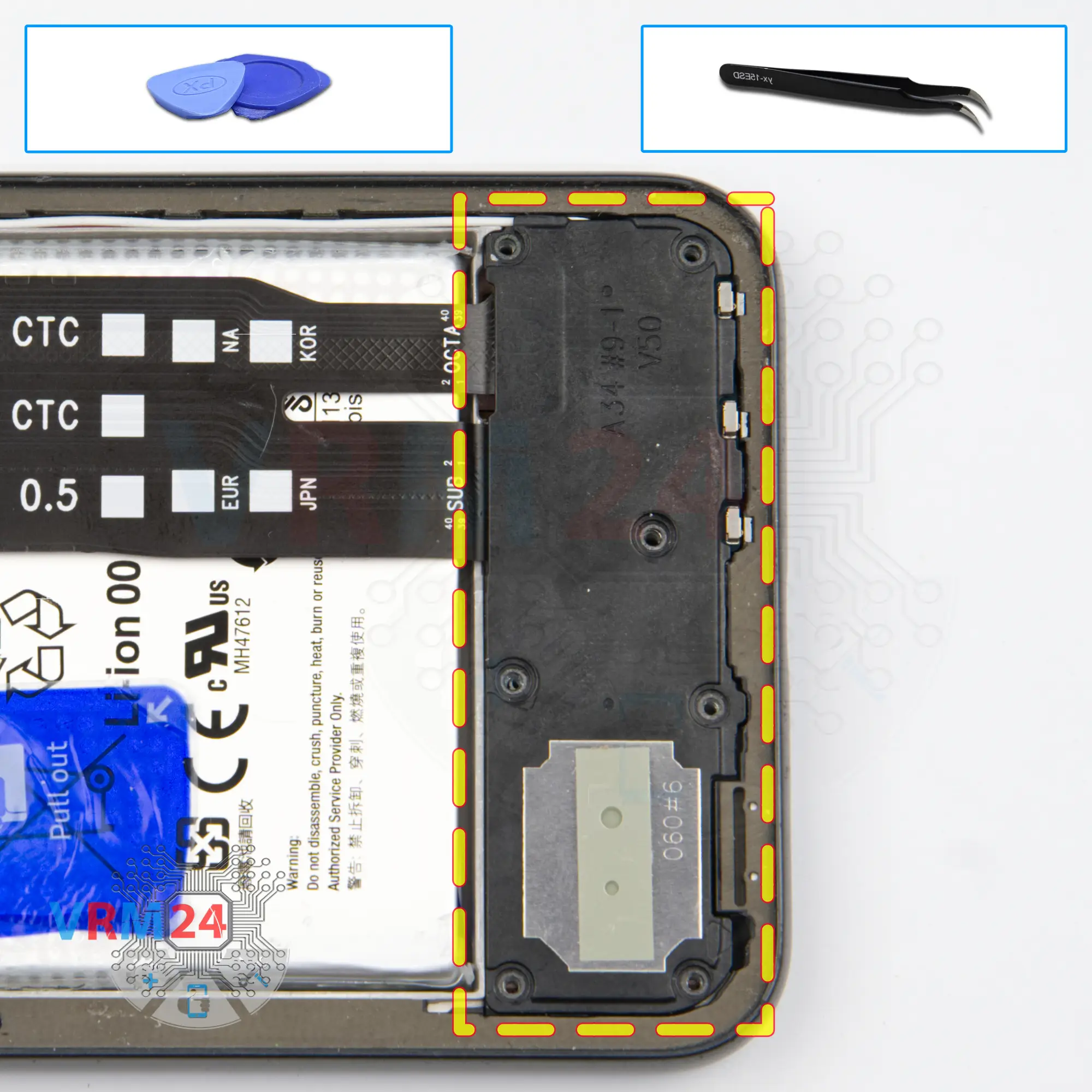
Step 8. Open the cover
Then we need to detach the cover at the bottom. We also find the right place where we can hook, gently lift and remove the cover.

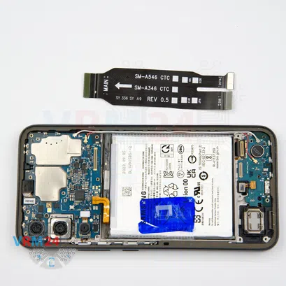
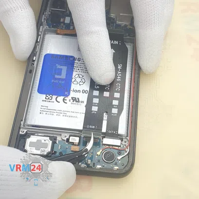
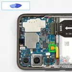
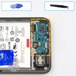
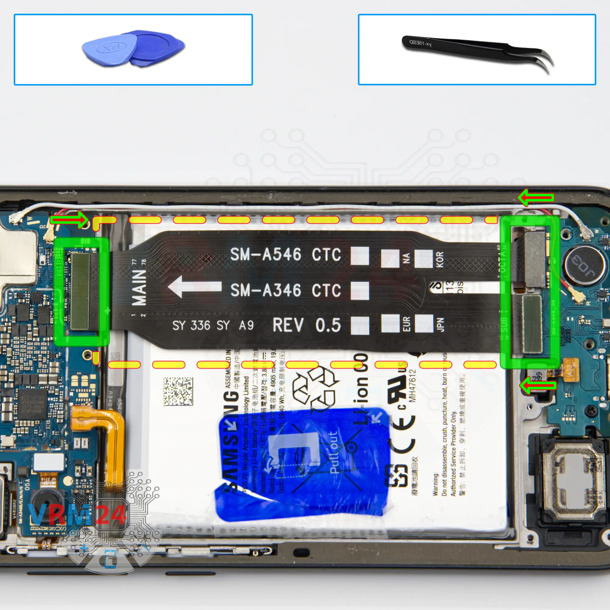
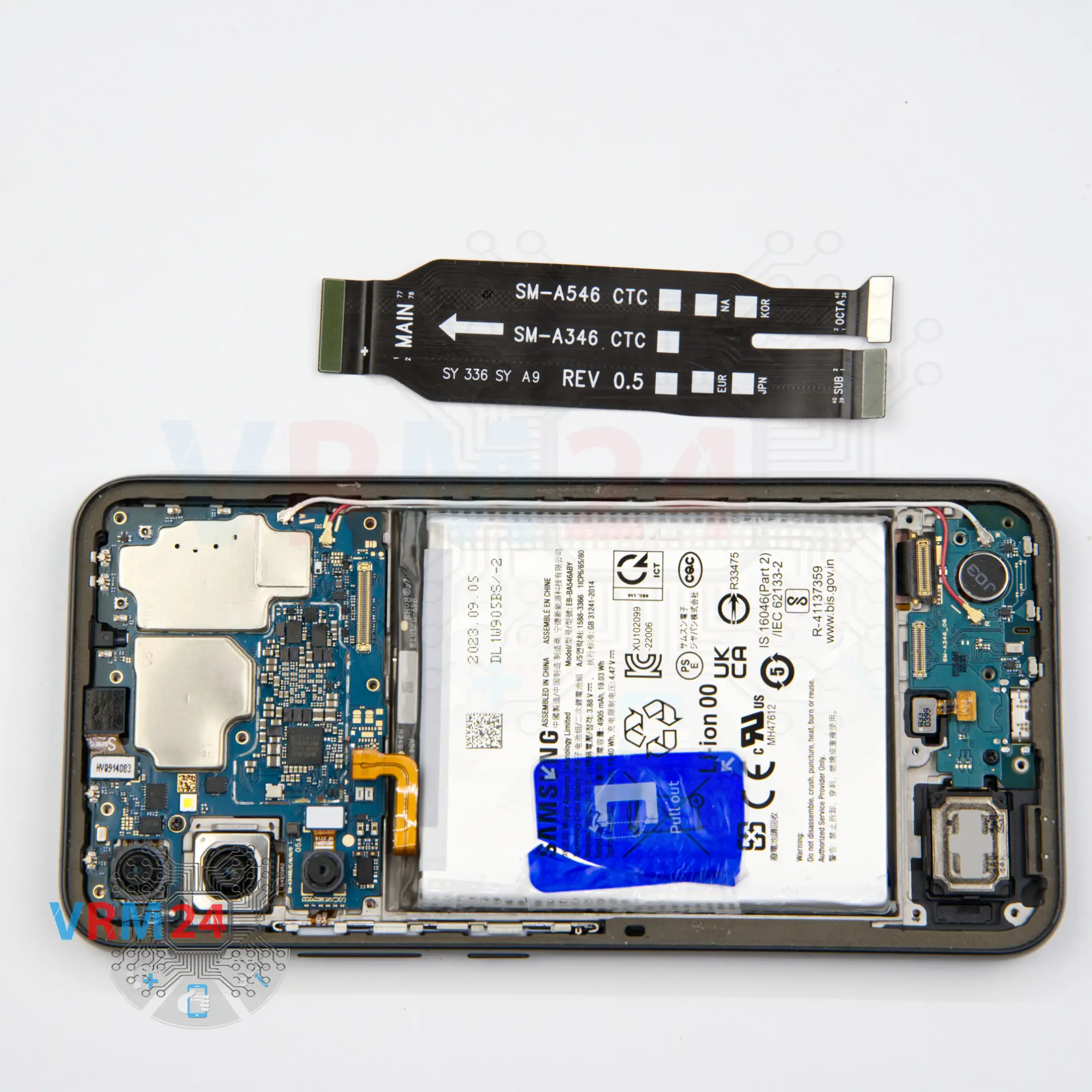
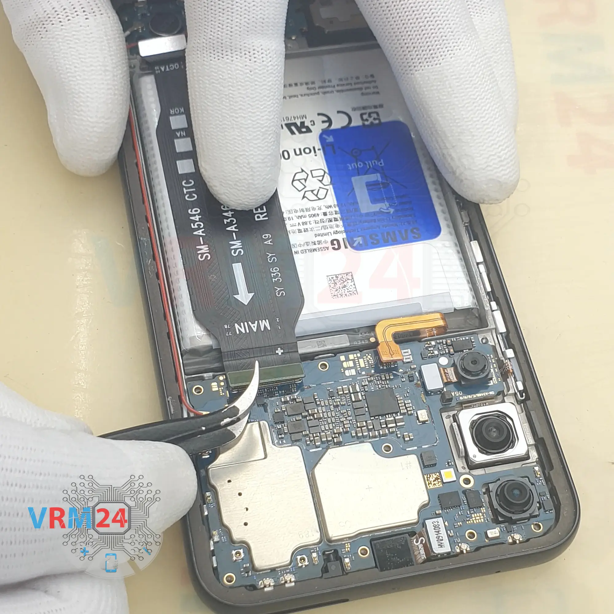
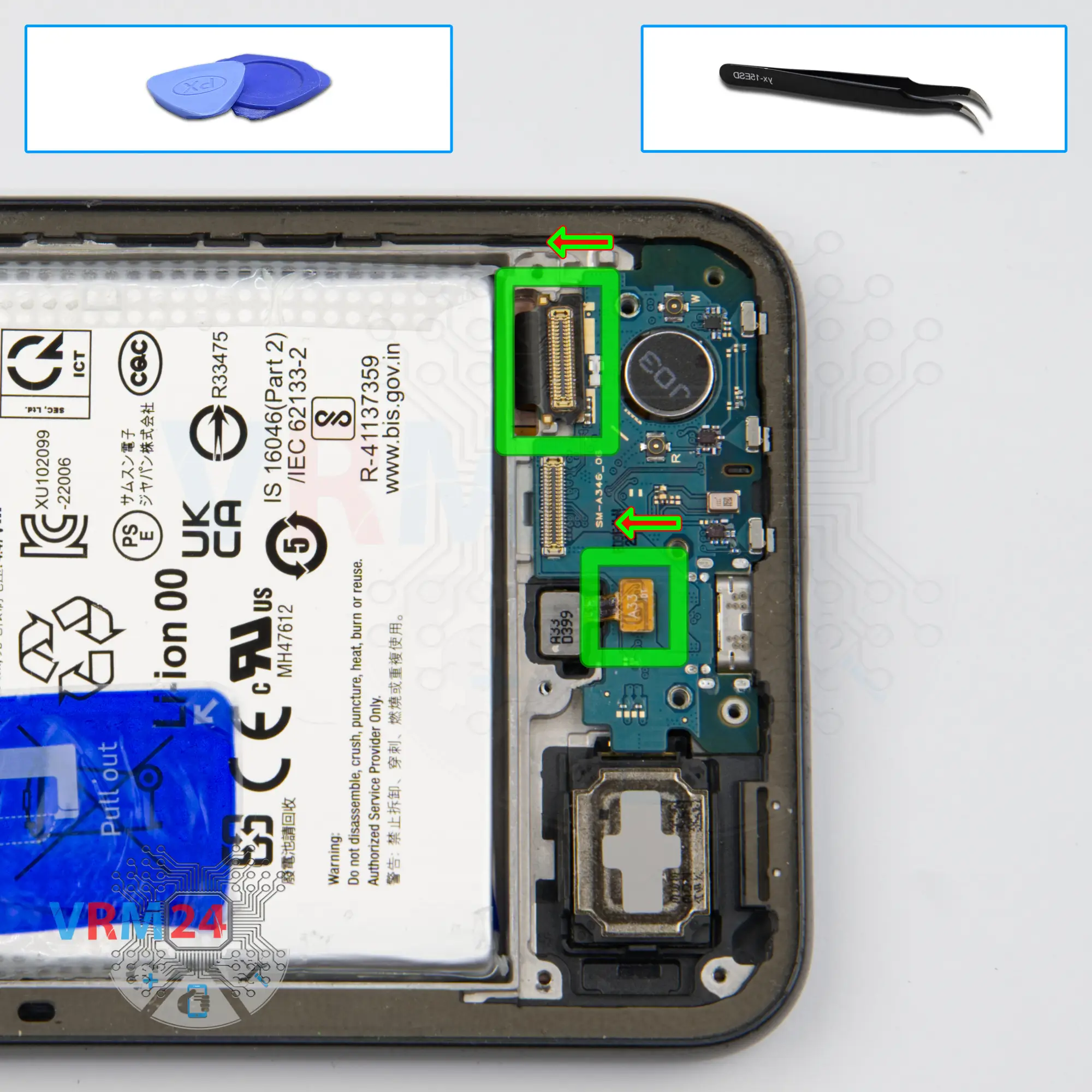
Step 9. Remove the interconnect cable
We disconnect the connectors on the sub-board and motherboard and remove the inter-board cable.
ℹ️️ An arrow on the FFC cable (flexible flat cable) indicates its correct position.

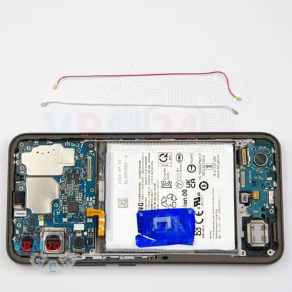


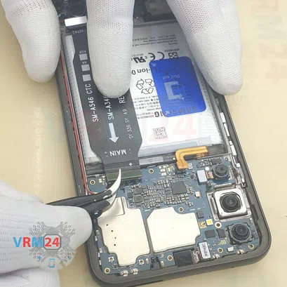
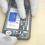
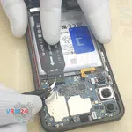
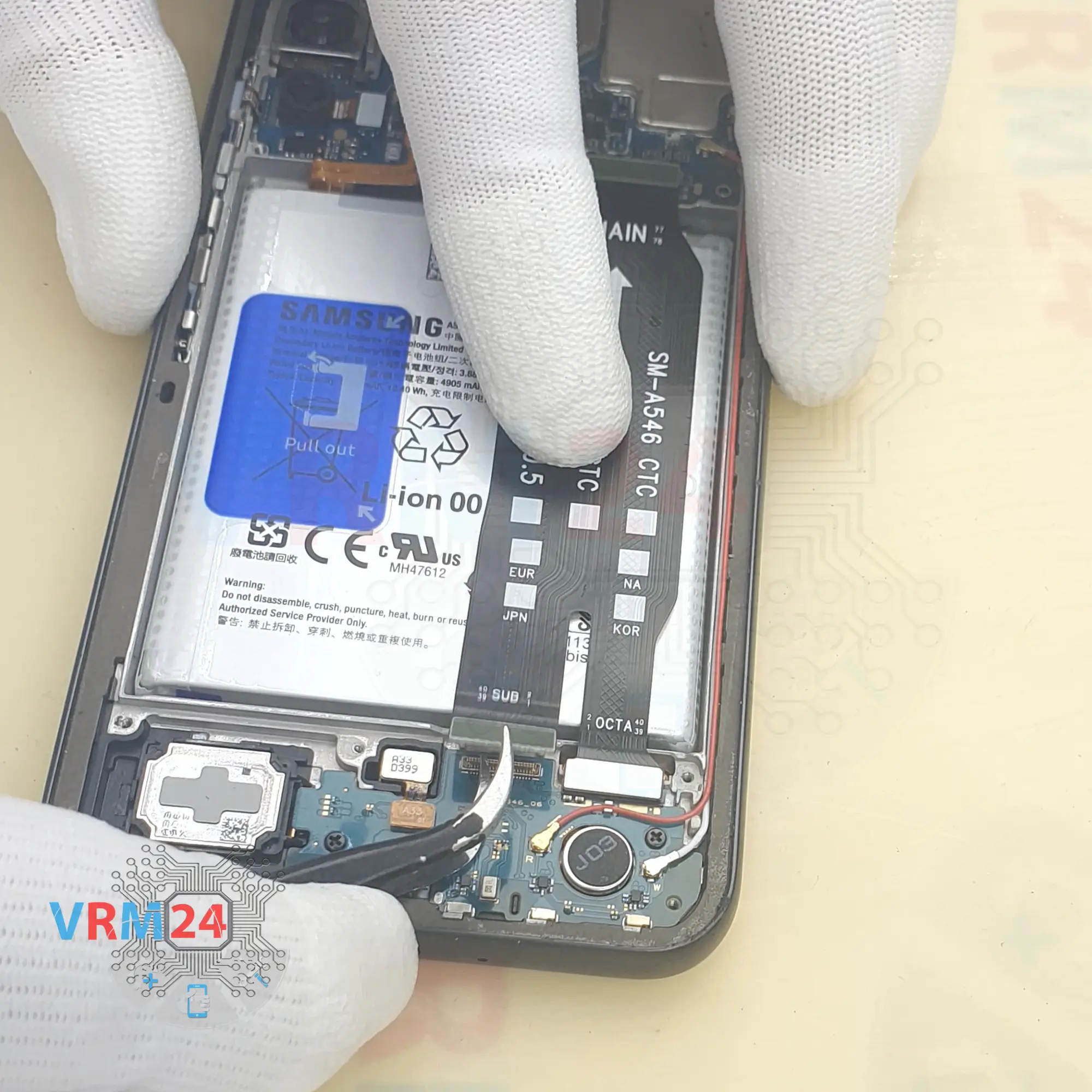
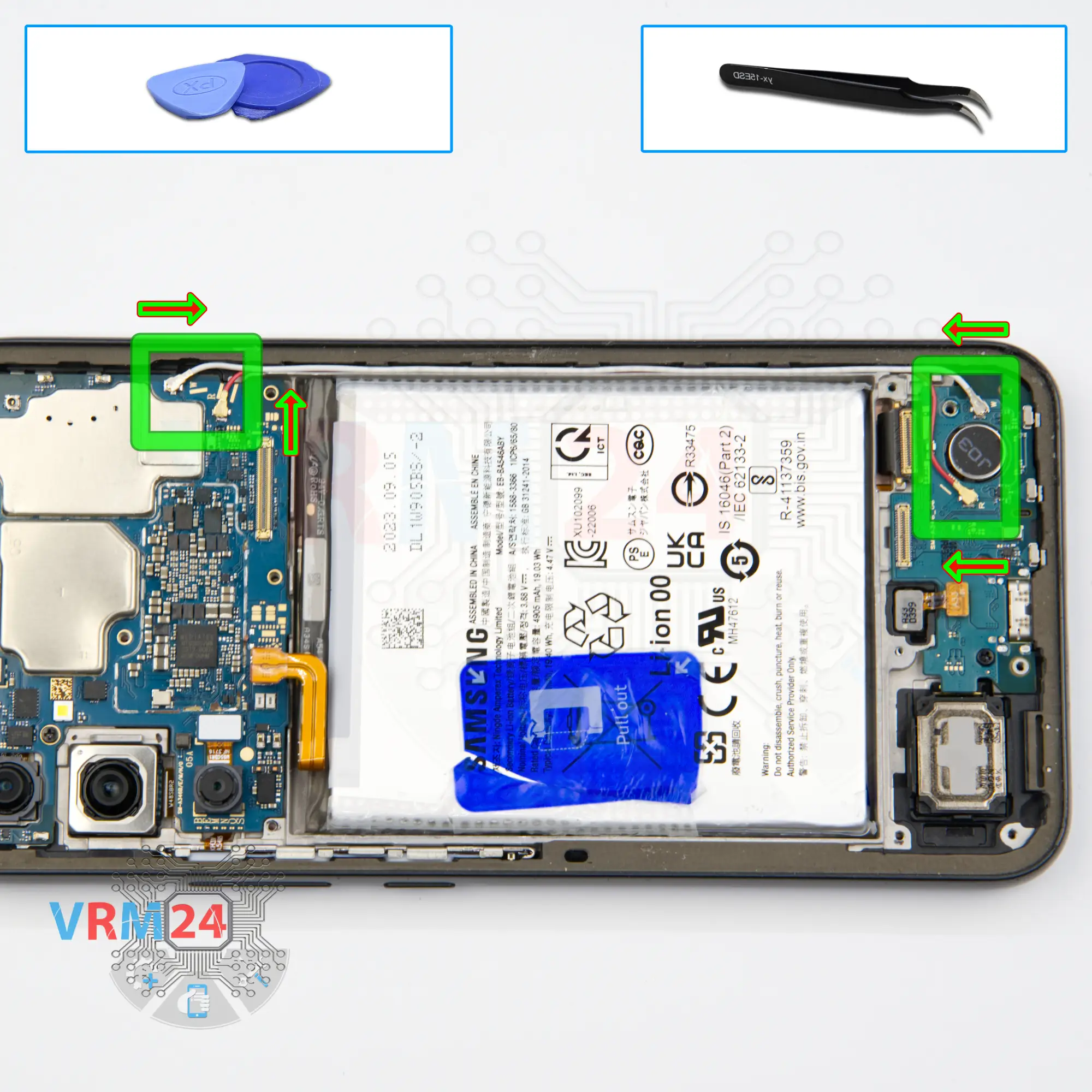
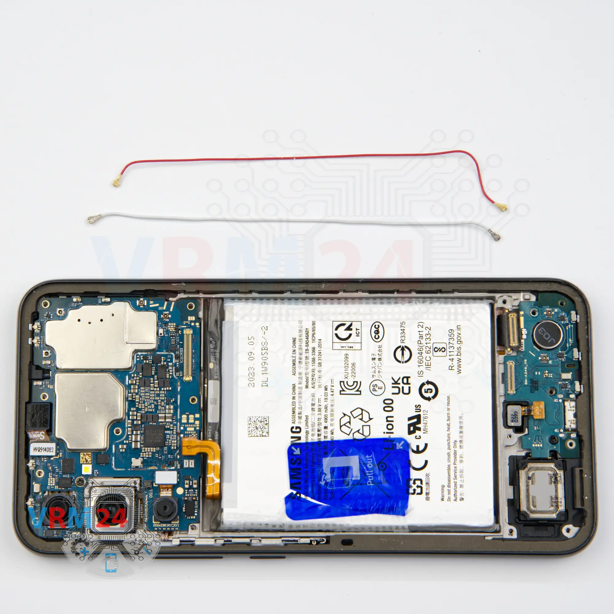
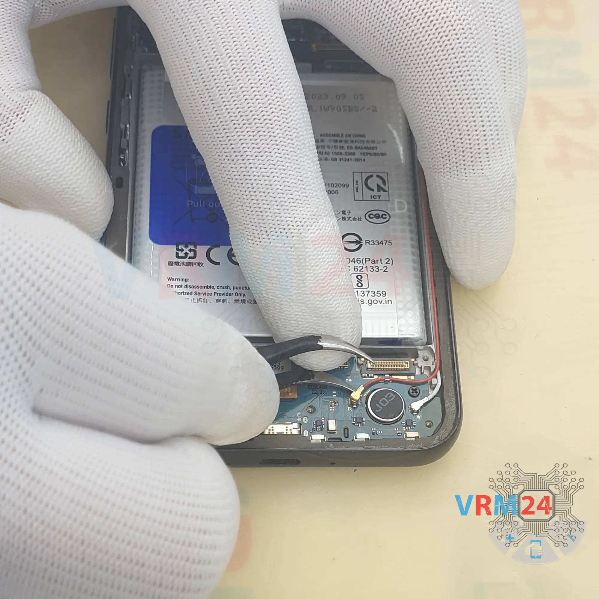
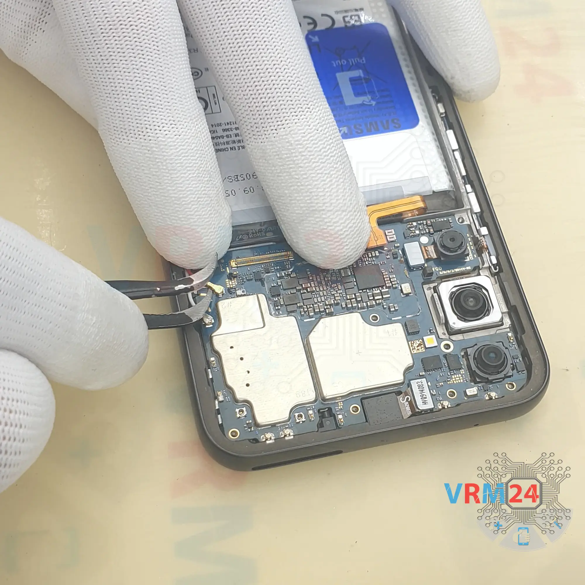
Step 10. Remove the coaxial cable
We then disconnect the coaxial cable connectors, release the cables themselves from the clips securing them to the boards and remove the two coaxial cables.
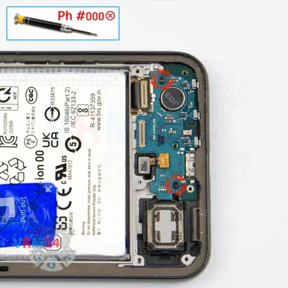


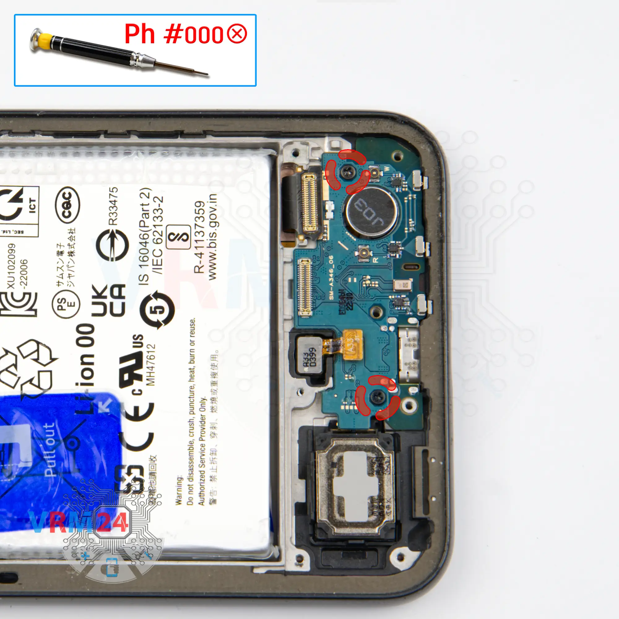
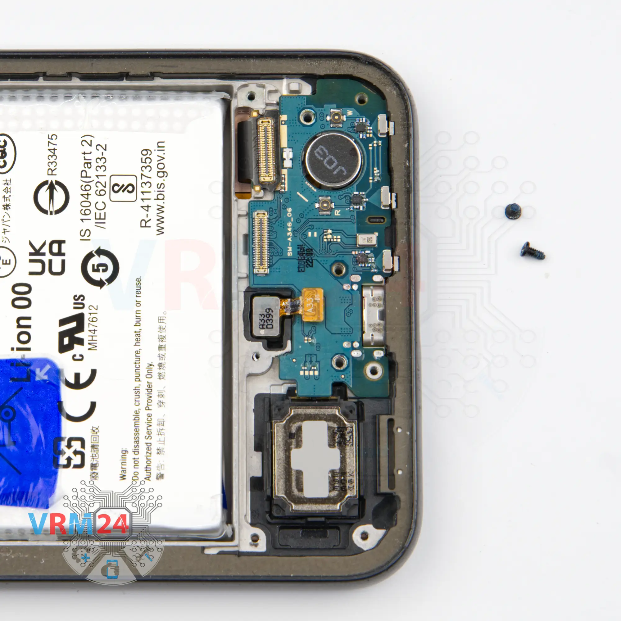
Step 11. Unscrew the screws
Then with a 1.5-millimeter Phillips screwdriver, we unscrew the two screws securing the sub-board.
Carefully unscrew the screws and place them separately, because the screws are different from the previous ones both in color and size, of course.

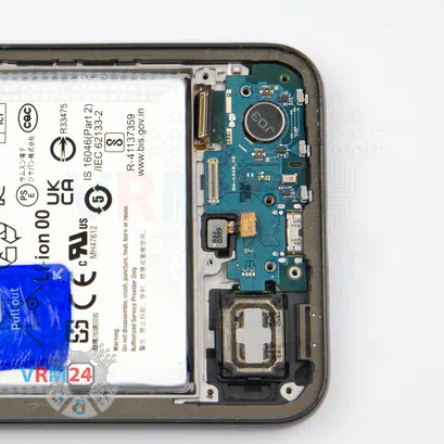


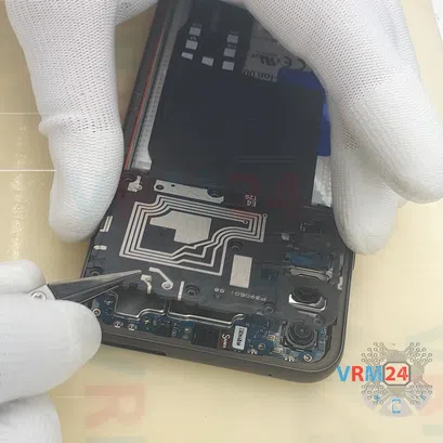
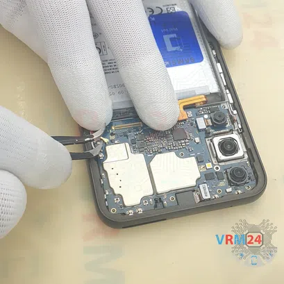
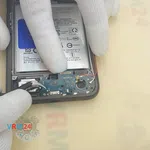
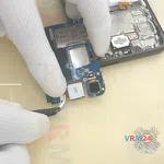
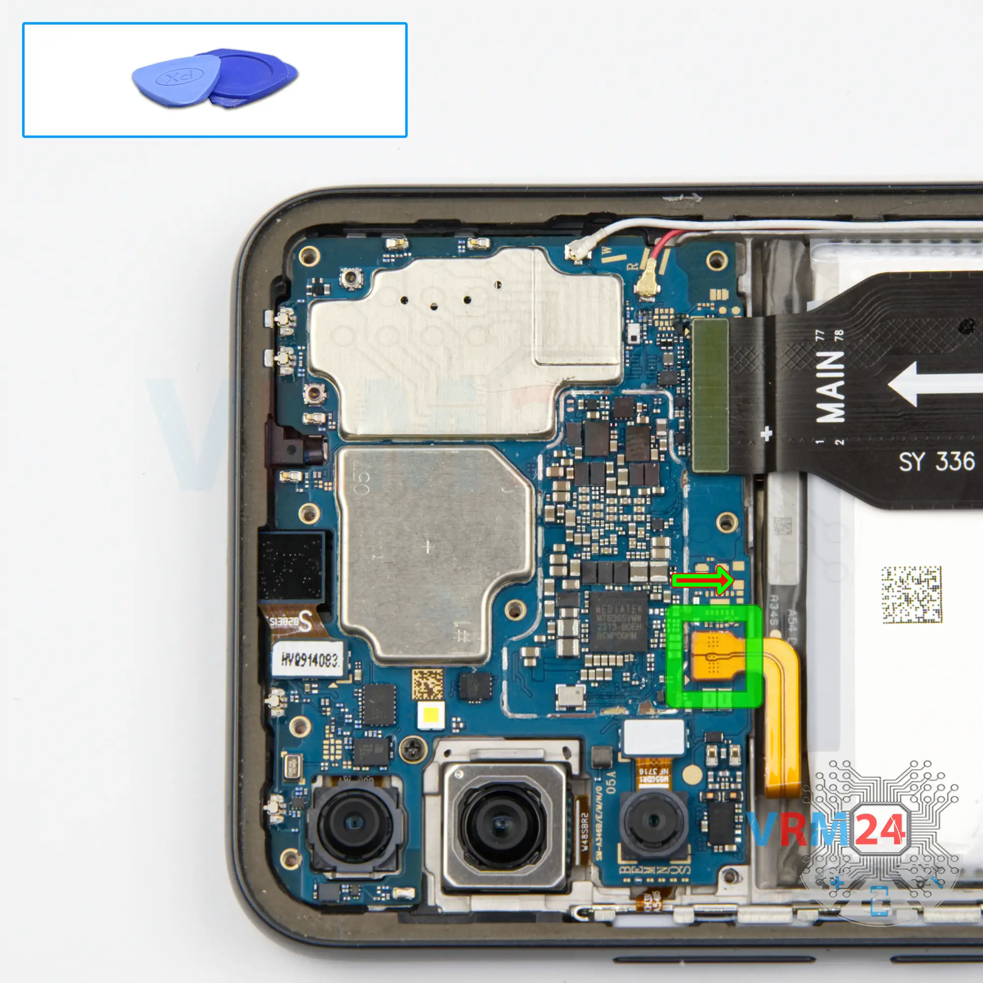
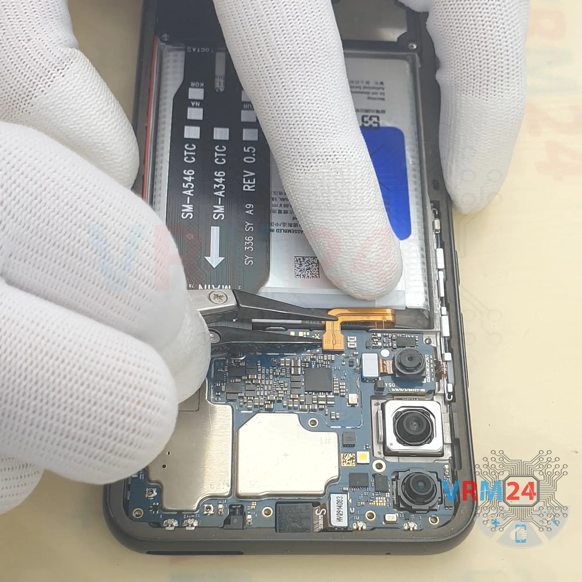
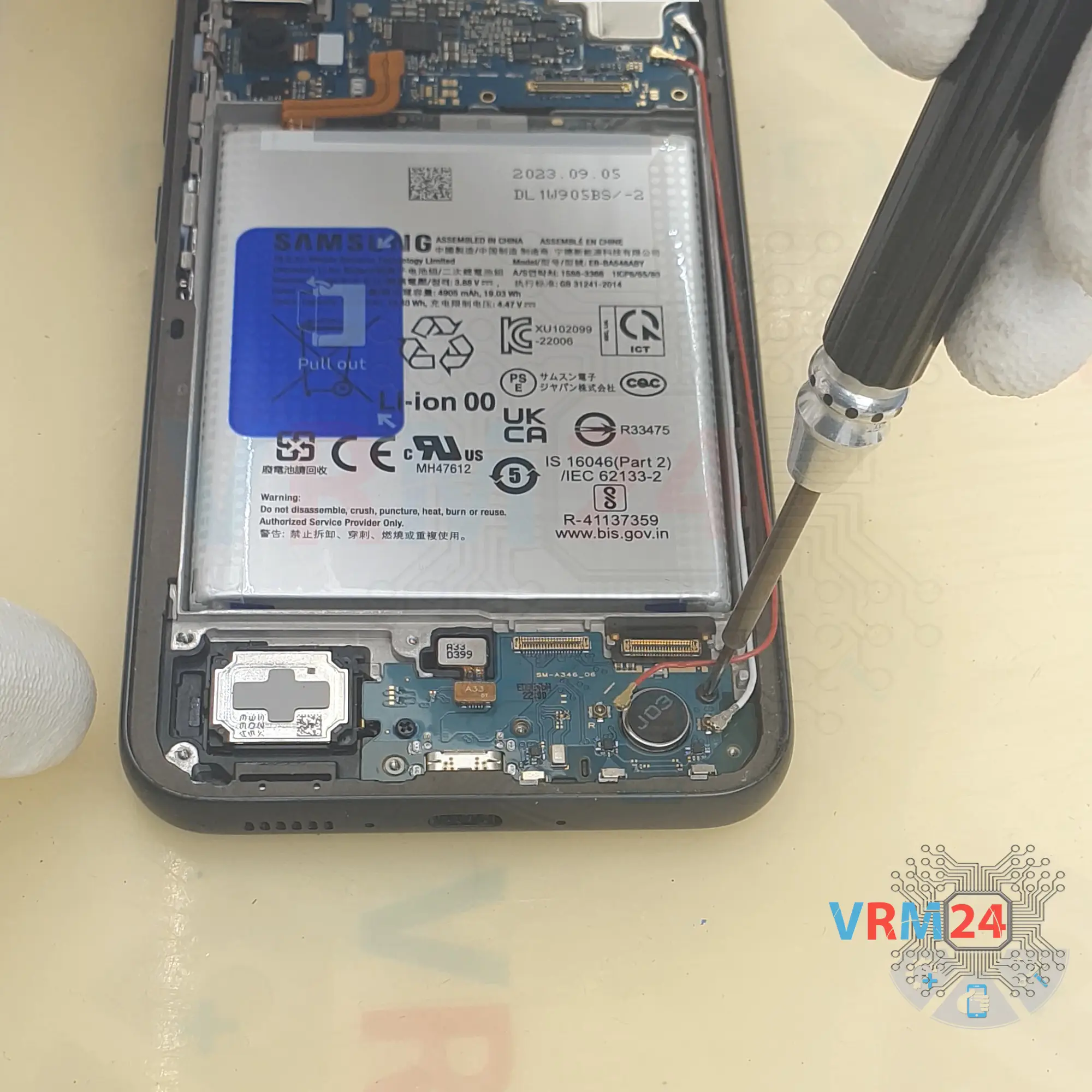
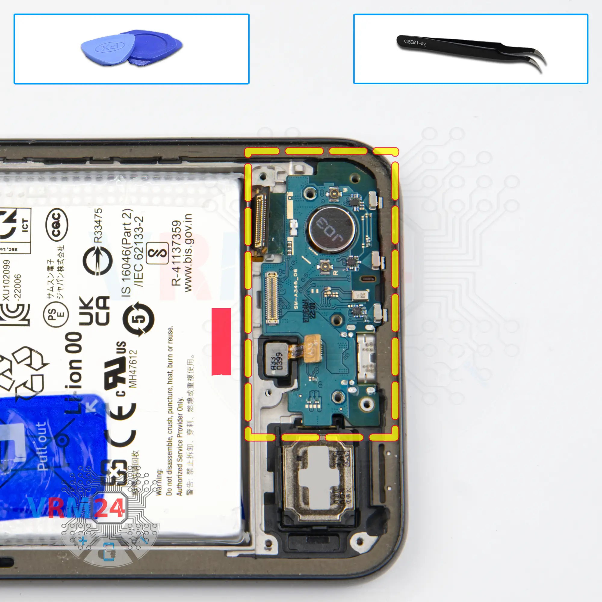
Step 12. Disconnect the connectors
We also disconnect the fingerprint sensor connector and we still have to detach the glued connector on the sub-board. To do this, we need to carefully pick up the connector from one edge and carefully unglue it and turn its cable aside so that it does not interfere with us.

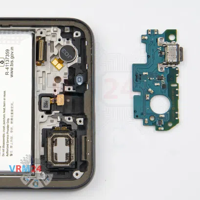


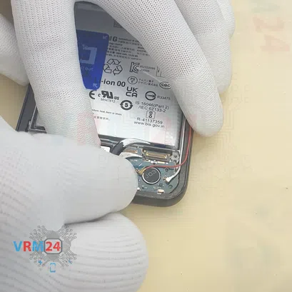
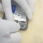
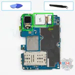
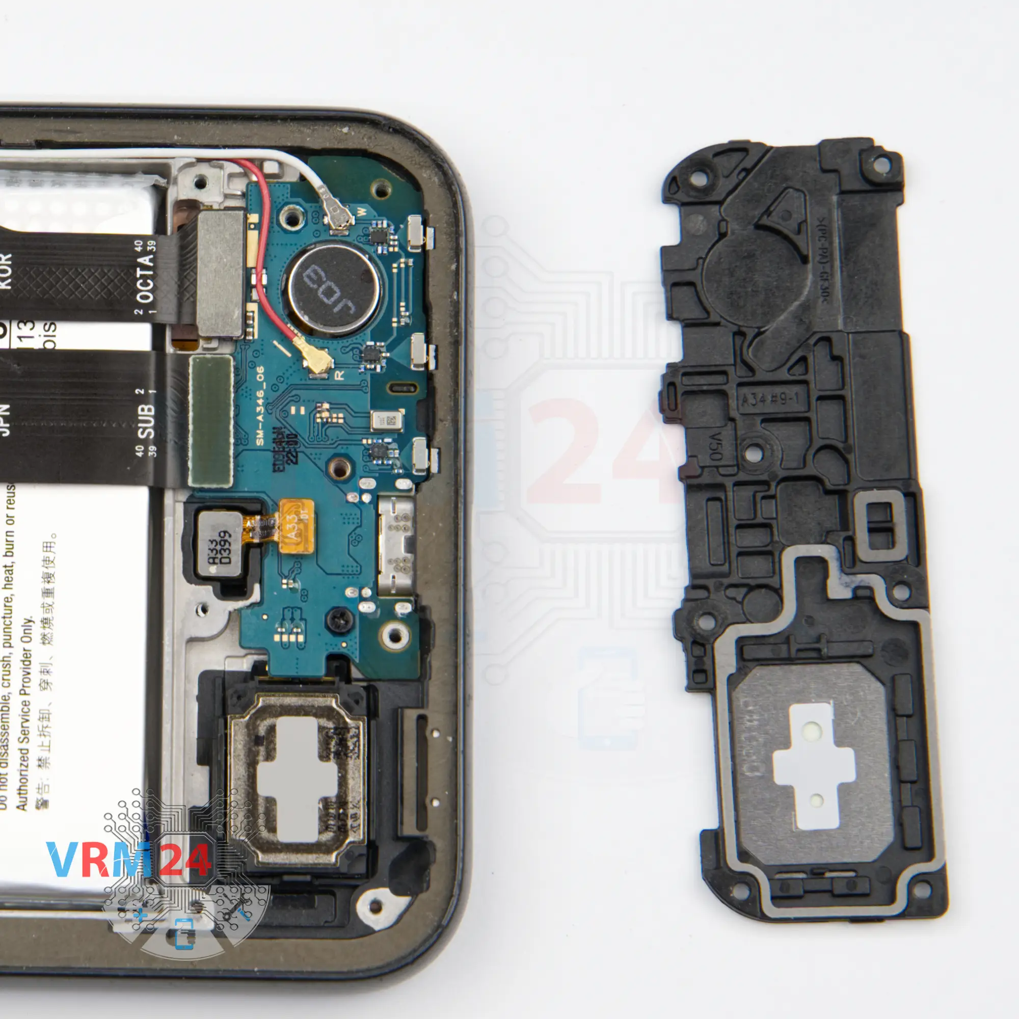
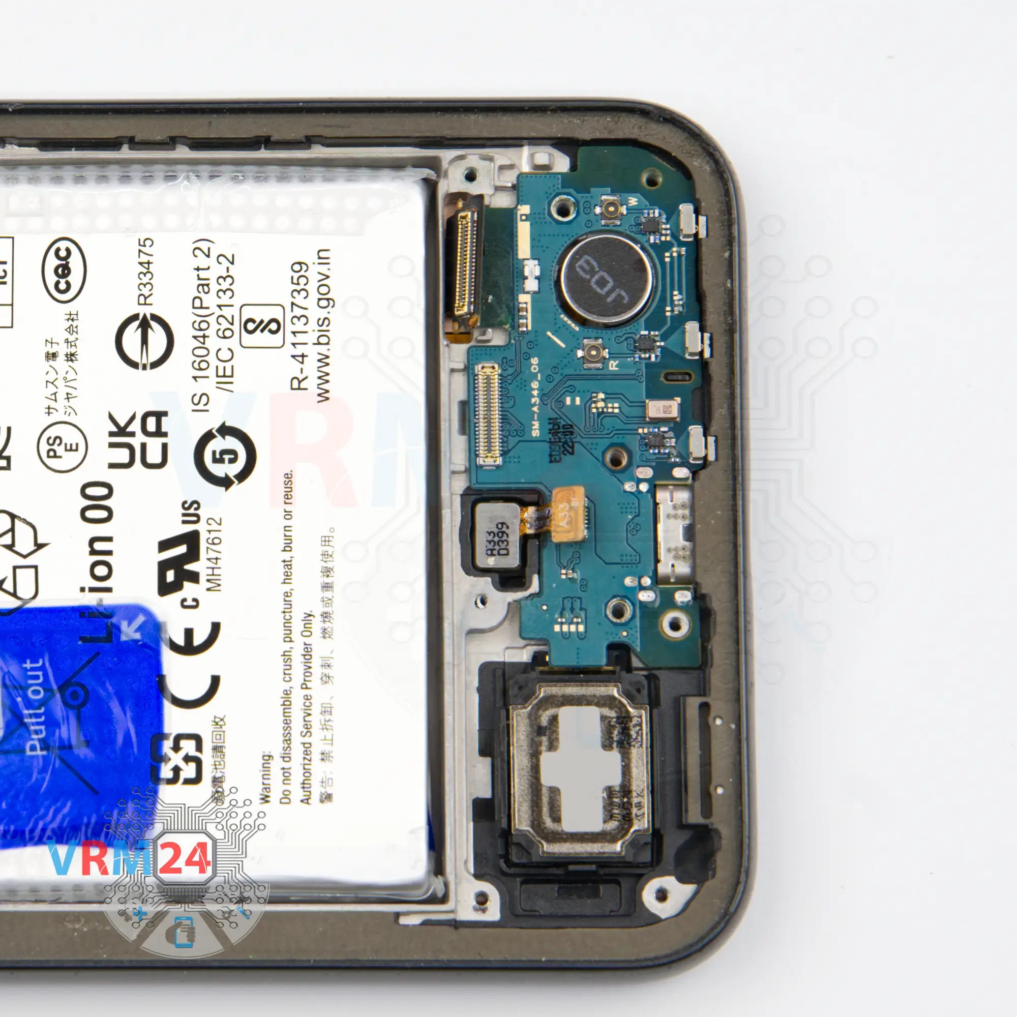
Step 13. Remove the sub-board
And now we can carefully remove the sub-board without any problems.
So, we take the sub-board out. On the sub-board we have the charging port, microphone.


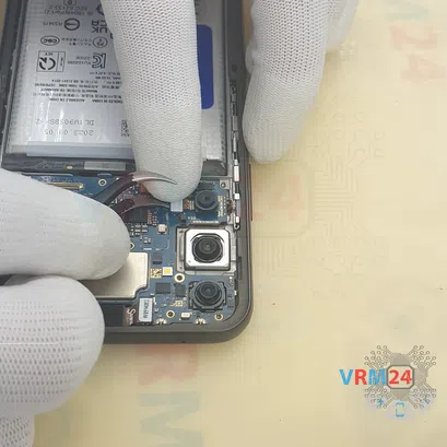


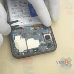
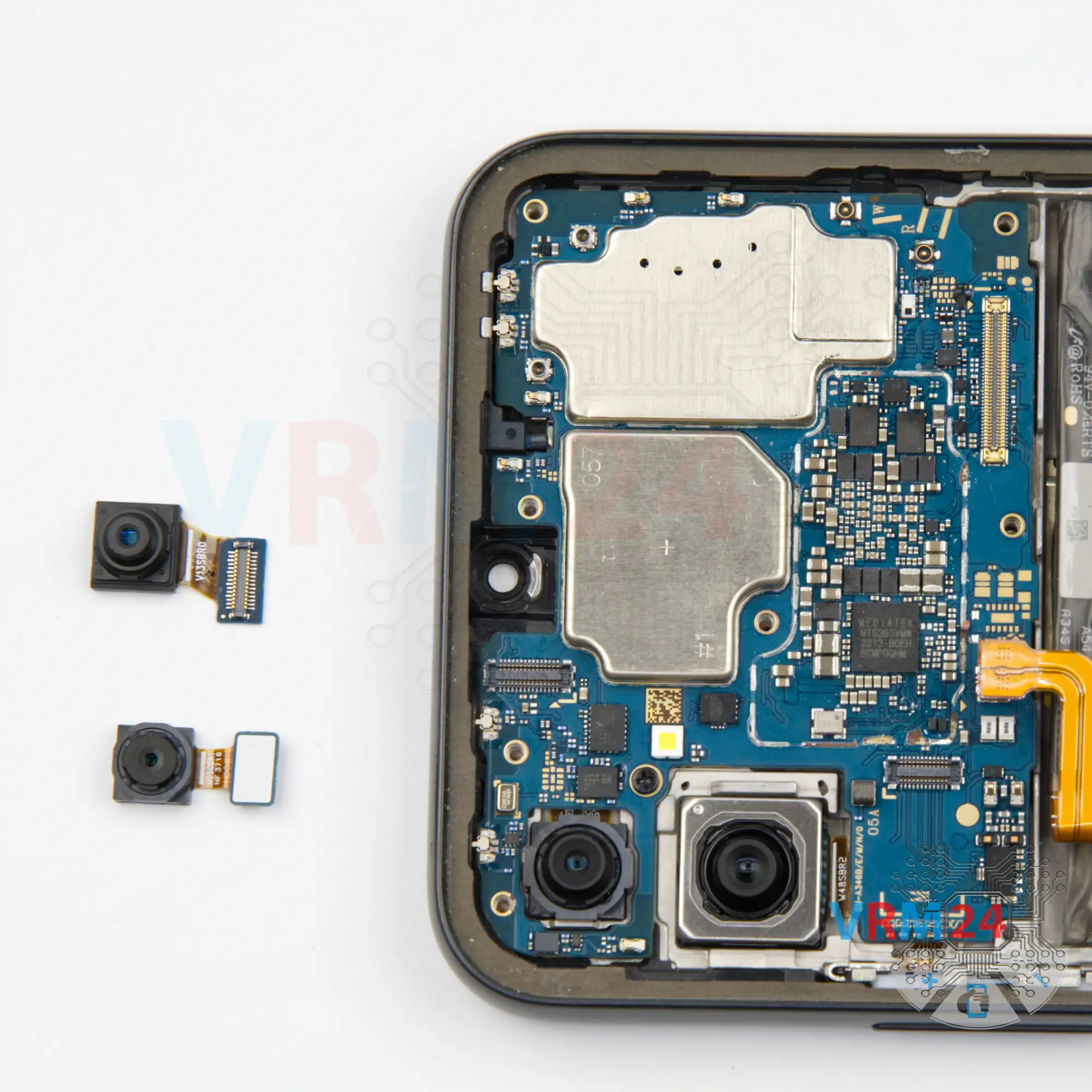
Step 14. Remove the cameras
Then we can detach one of the rear cameras. It's better to hold the cameras by the base or by the cable so that they don't accidentally fly out and we don't damage the lenses.
And we can also detach the front camera. Just like that, we gently hold it, disconnect the connector and take out the front camera.

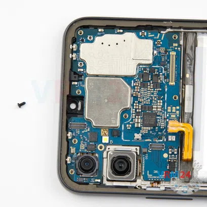

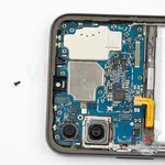
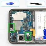
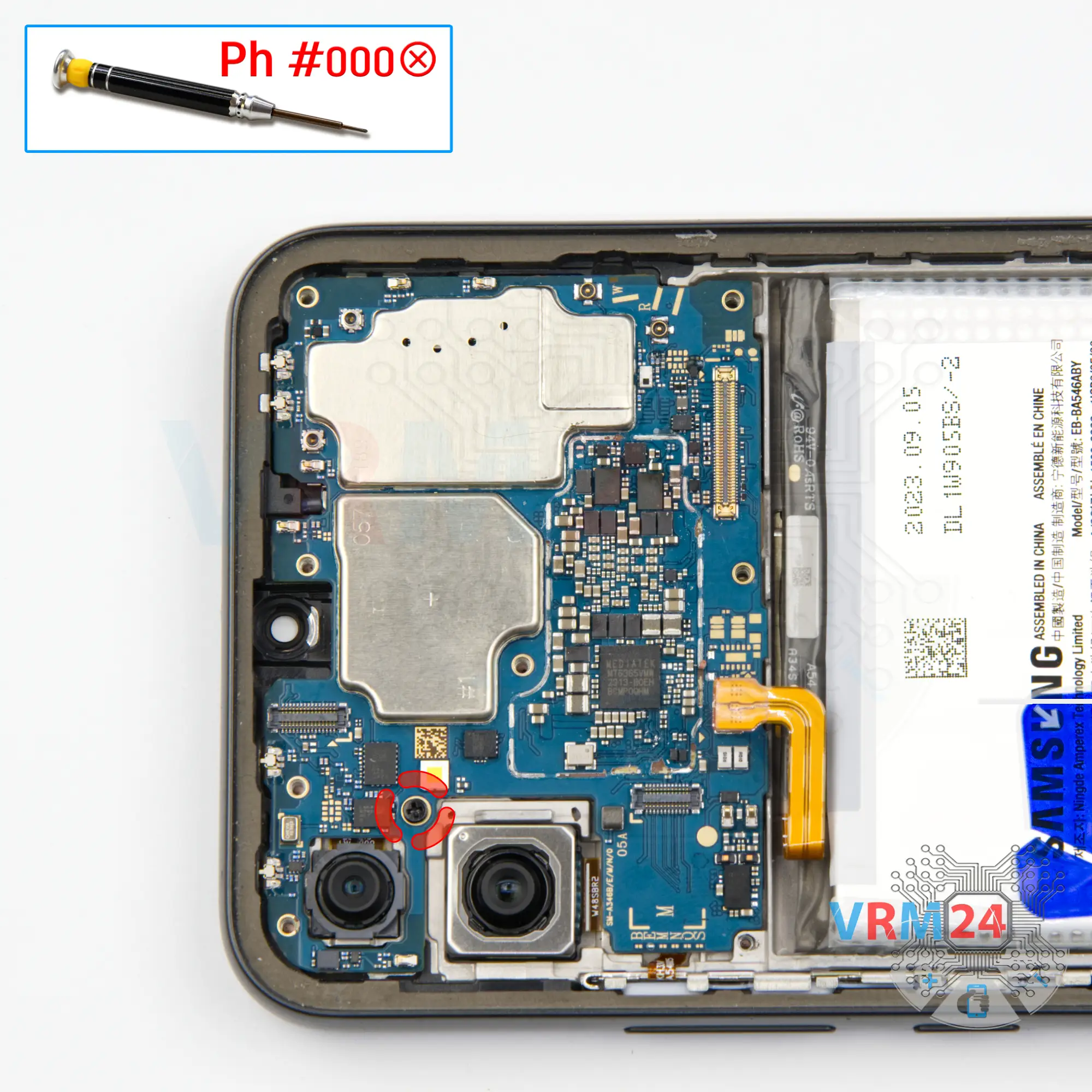
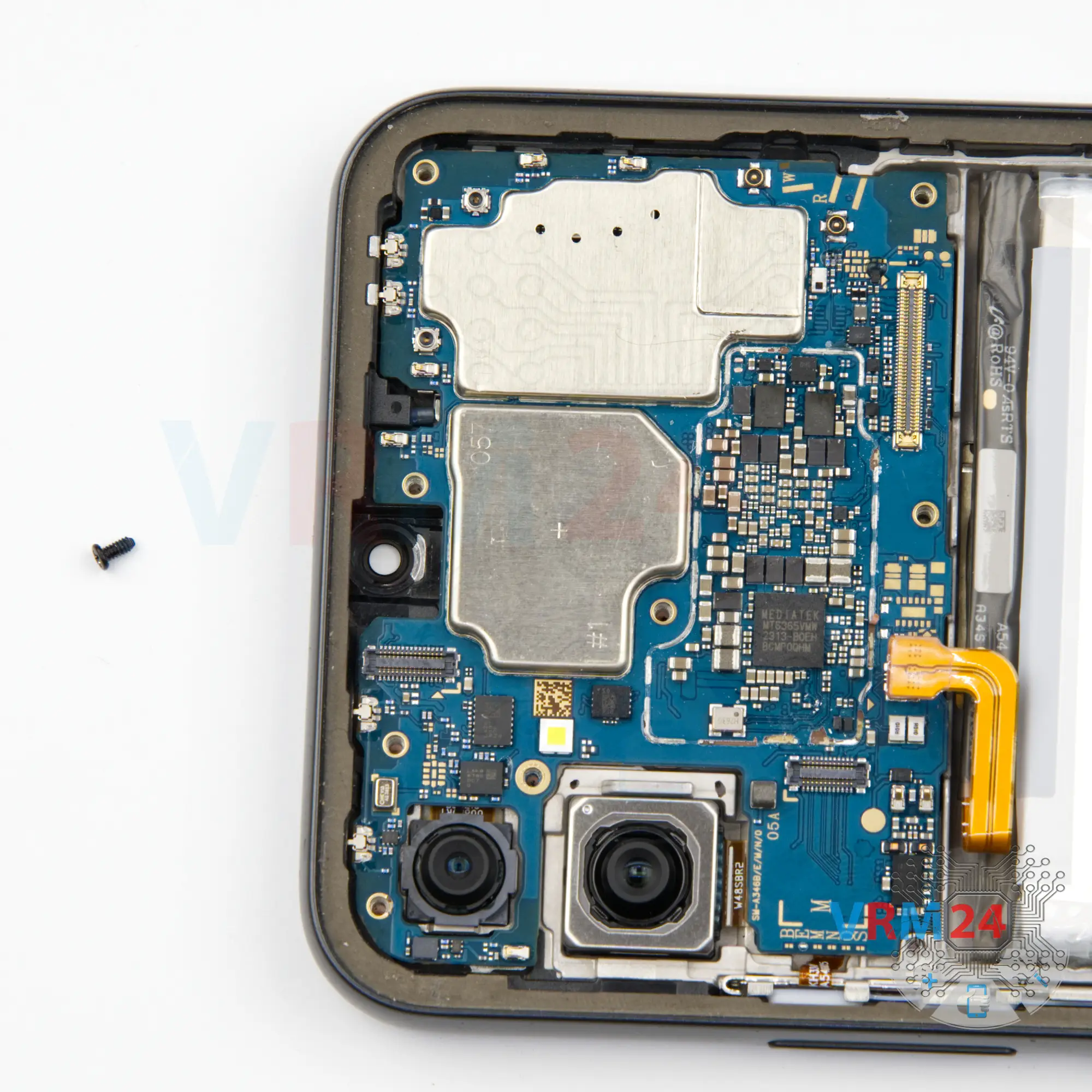
Step 15. Unscrew one screw
Using a Philips 1.5 mm screwdriver (PH #000), unscrew one screw securing the motherboard.


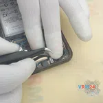
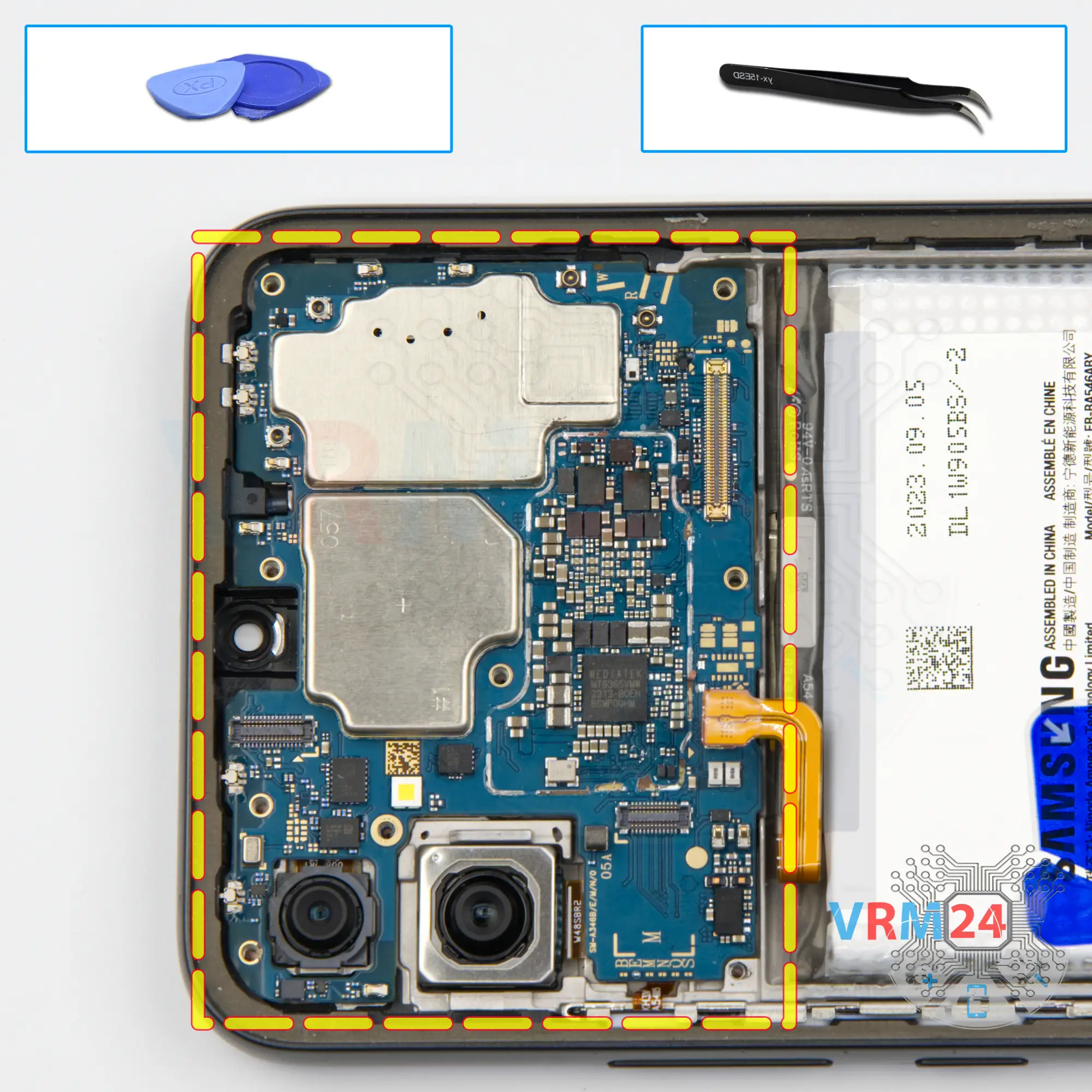
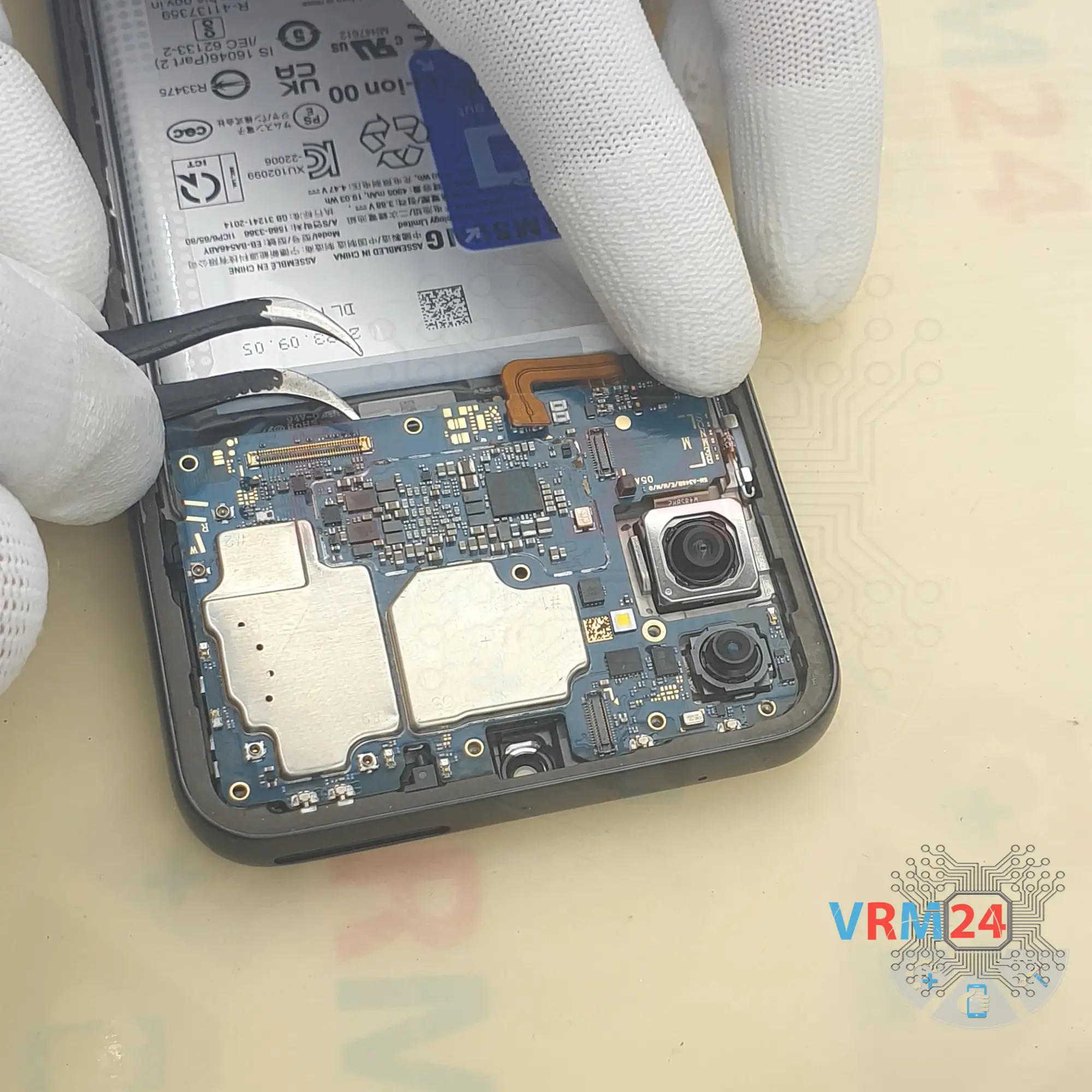
Step 16. Remove the motherboard
After that we can detach the motherboard. We find the right place where we can gently pry and remove the motherboard.
⚠️️ Do not bend the circuit board when removing it or push tools under it. Unbeknownst to yourself, you can damage components or cables from the inside.

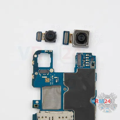


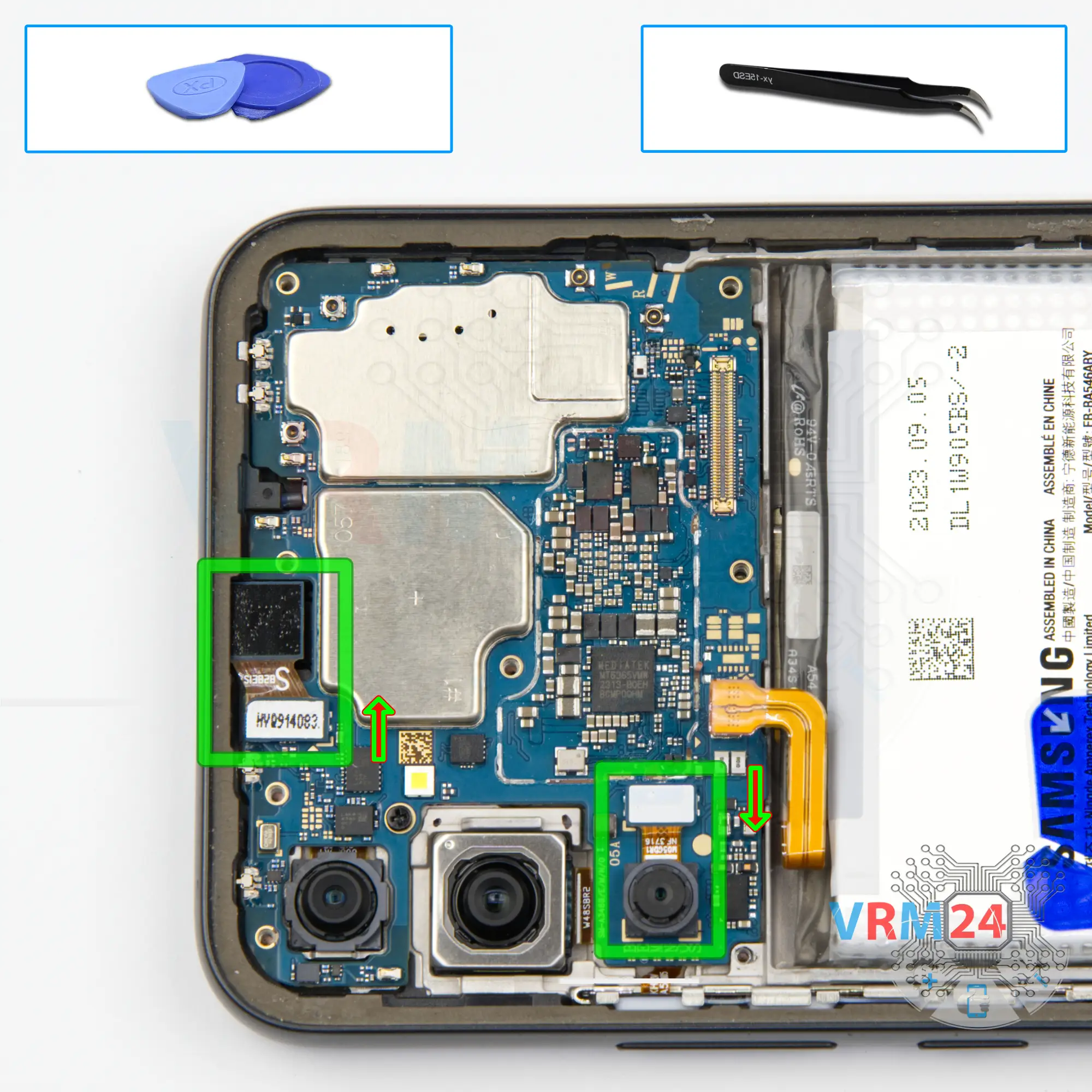
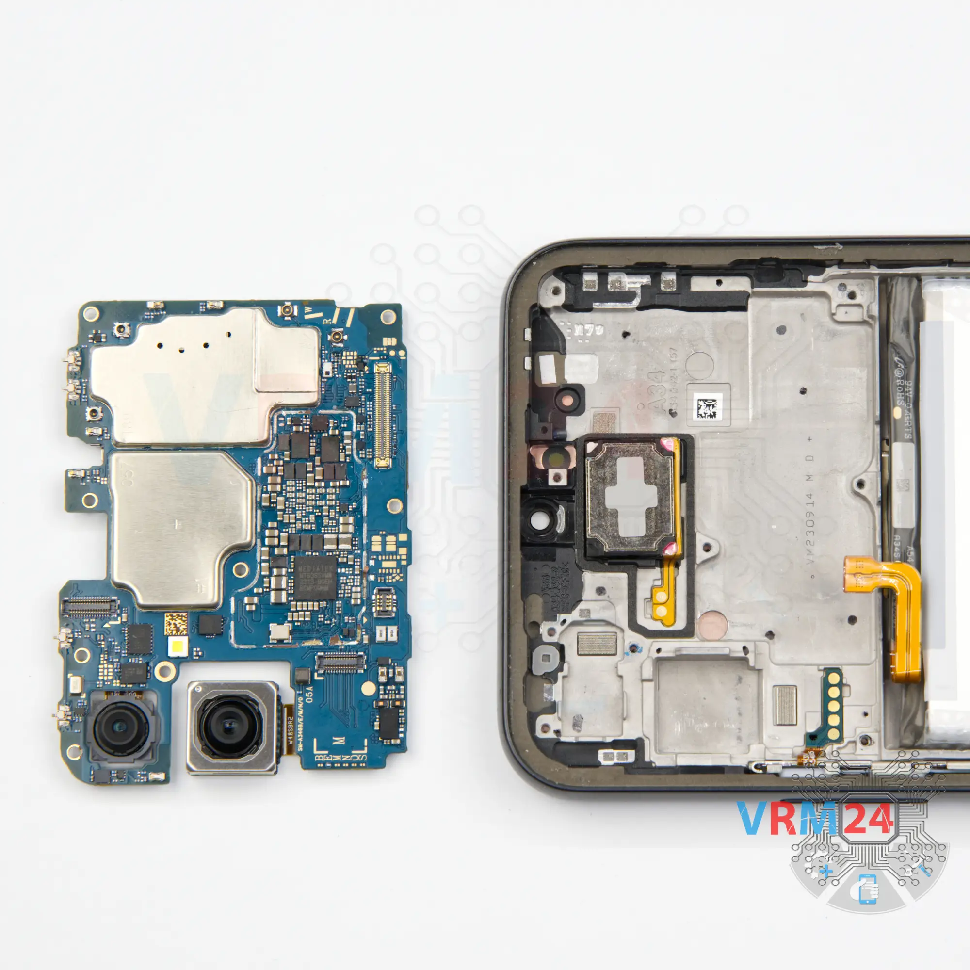
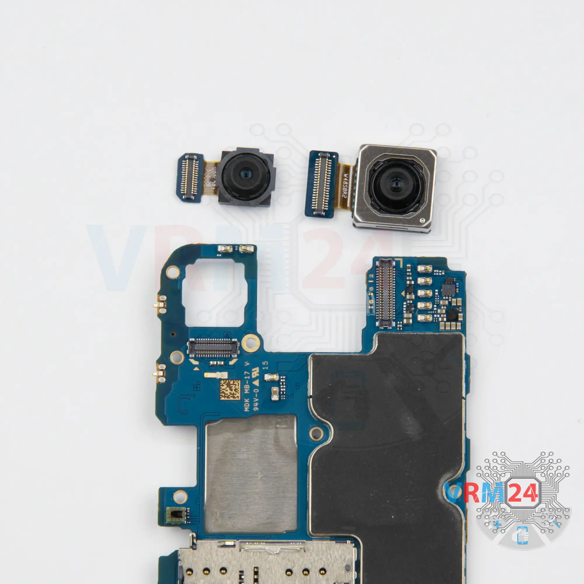
Step 17. Remove the cameras
We turn the motherboard over and disconnect the two rear cameras. We also hold the cameras so that they don't fall out and we don't damage anything.


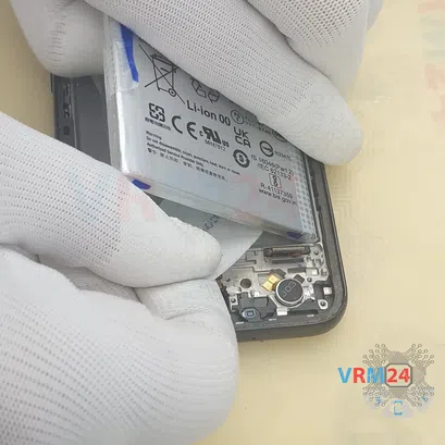

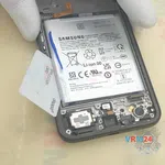

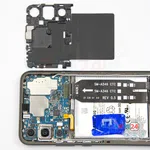
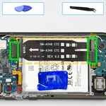
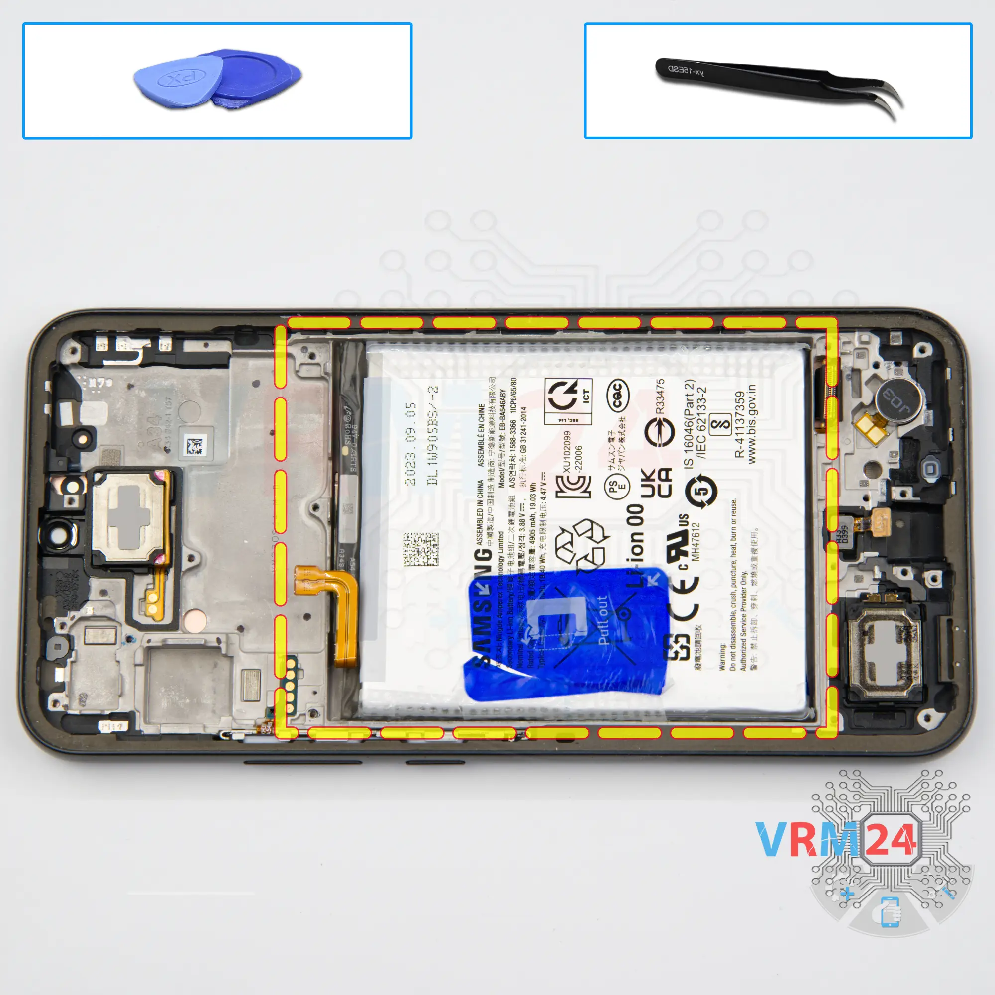
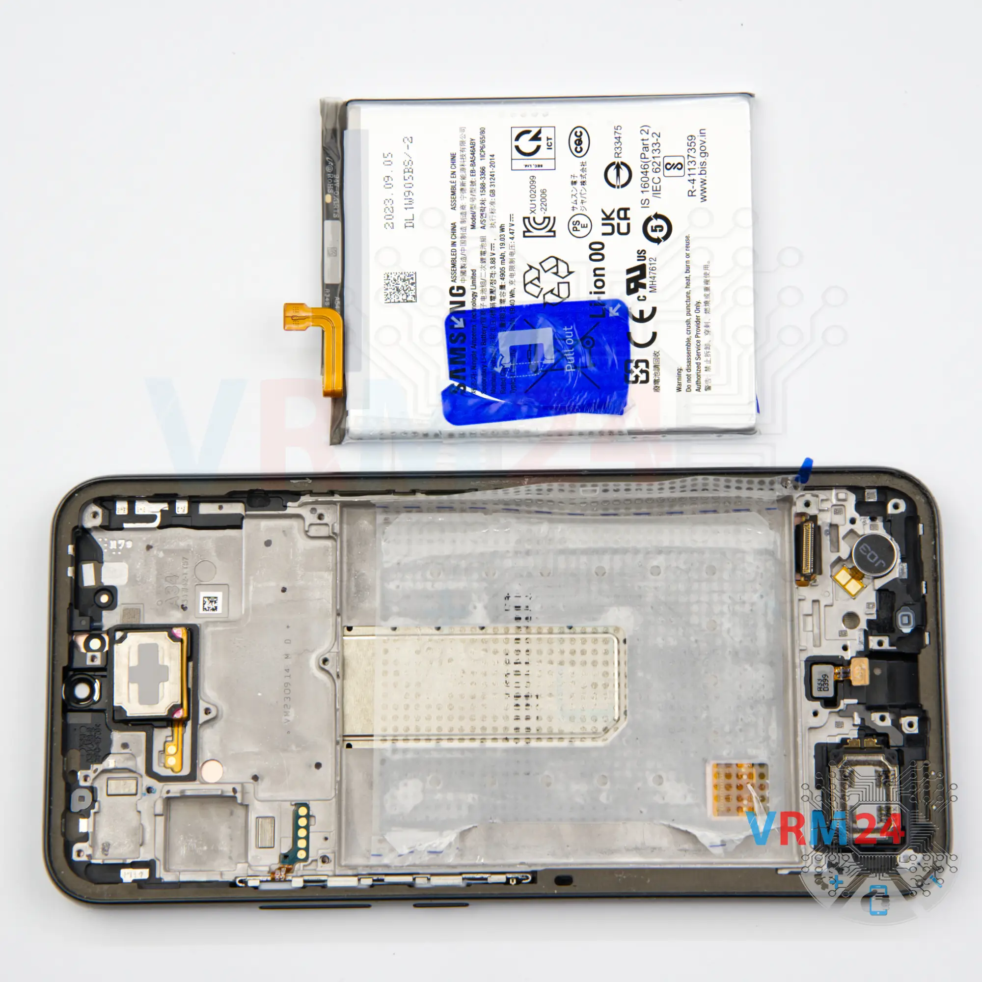
Step 18. Remove the battery
Finally we move on to detach the battery.
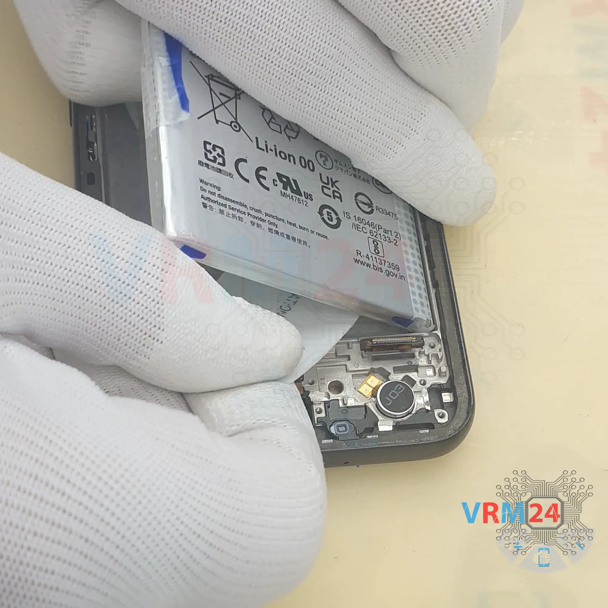
We need to unwrap the blue tab in the middle and the two transparent tabs on the edges so that they don't interfere with detaching the battery. However, as is often the case with this type of battery, if we just pull up on the blue tab, nothing happens. Because the adhesive base of the battery is actually soldered to the battery - possibly due to temperature variations or extreme heat.
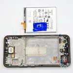
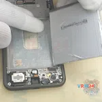
So, we try gently peeling back the tabs around the edges, pulling on the blue tab in the middle, but nothing works. So, we take a thin tool, gently try to lift the battery in a few places.
It is really important to be careful not to force the battery, so as not to damage the battery shell.
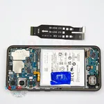
So, we try to lift up the battery, run a plastic card under the battery and carefully cut off the part that's soldered on so that we can detach the battery.
We carefully run the plastic card along the side of the battery, back and forth, cutting off the adhesive part that is stuck and of course trying to carefully lift the battery.
And, we try to gently lift the battery. We don't need to hurry, we don't need to force it, so that we don't accidentally damage the battery shell.
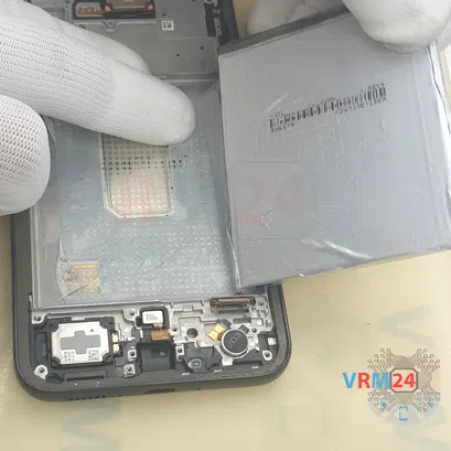
And finally, we detached the battery. As we can see, under the battery we have an adhesive transparent coating and places where the battery we have soldered or very strongly held by this adhesive backing.

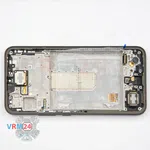
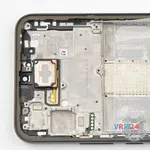
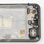
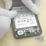
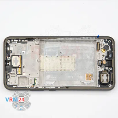
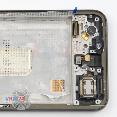
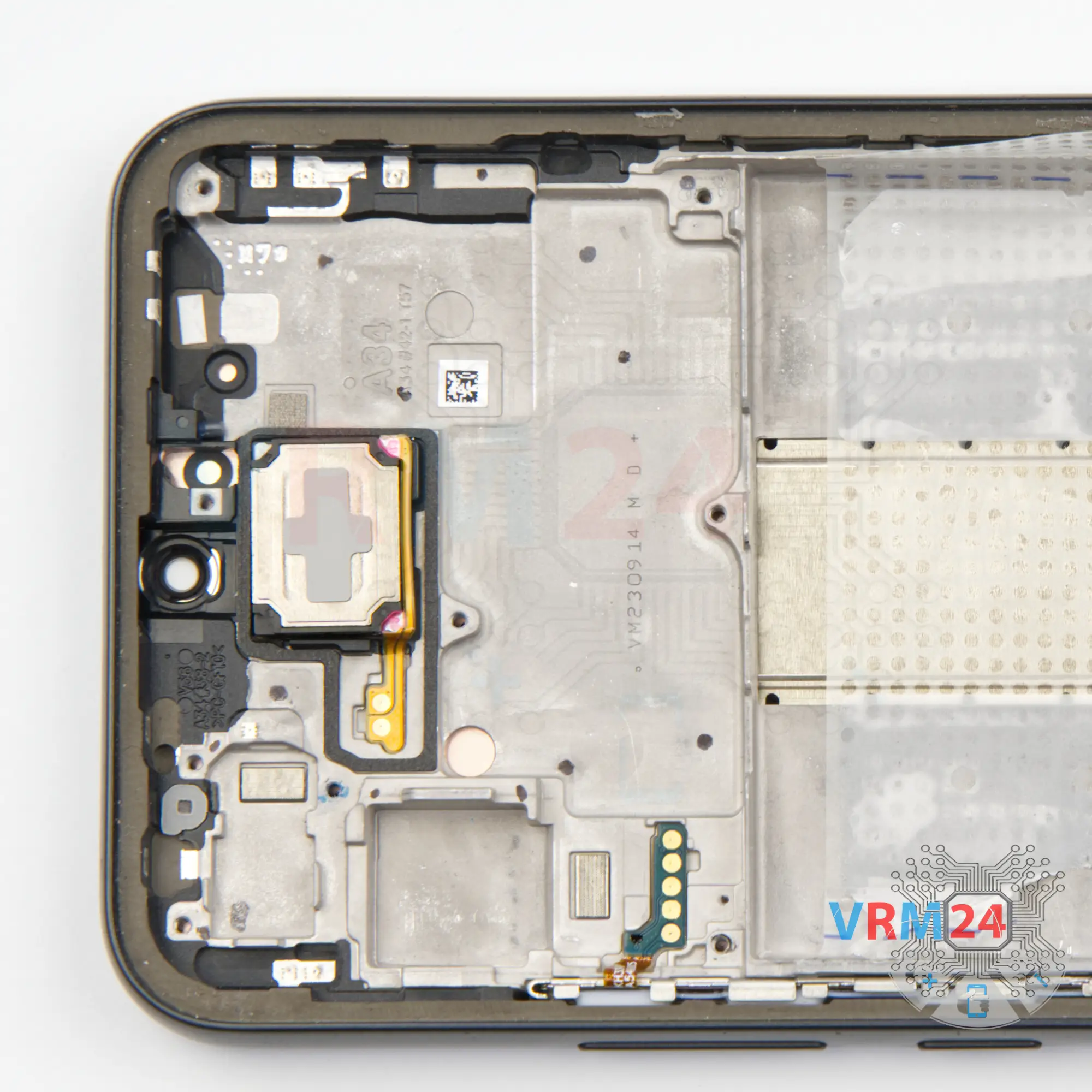
Step 19. In the display frame remained
ℹ️️ In the display frame remained: the earpiece speaker, loudspeaker, fingerprint sensor, and vibration motor.
Detailed disassembly instructions of Samsung Galaxy A34 SM-A346 in the video, made by our mobile repair & service center:
If you have a question, ask us, and we will try to answer in as much detail as possible. If this article was helpful for you, please rate it.

Disassembling\Repair has medium complexity and takes about minutes in time.
Our manual is suitable for all models Samsung Galaxy A34 SM-A346 — Samsung Galaxy A34 SM-A346E, SM-A346B, SM-A346B/DS, SM-A346B/DSN, SM-A346E/DS, SM-A346E/DSN, SM-A346M, SM-A346M/N, SM-A346M/DSN, SM-A3460 released for markets in different countries.
Back to the list