⚠️️ Before disassembling, do not forget to turn your phone off.
Teardown difficulty:
Moderate
Moderate
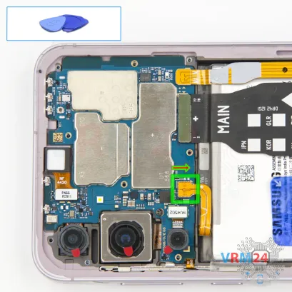
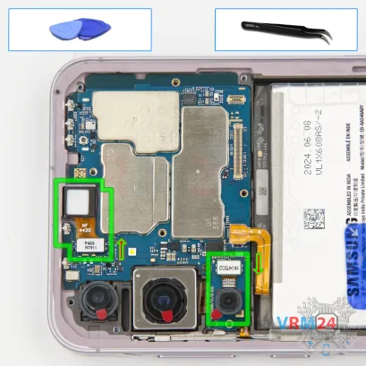
Recommended tools


Disassembly/Repair of the mobile device Samsung Galaxy A55 SM-A556 (Samsung Galaxy A55 SM-A556V, SM-A556B, SM-A556B/DS, SM-A556E, SM-A556E/DS, SM-A5560) with each step description and the required set of tools.

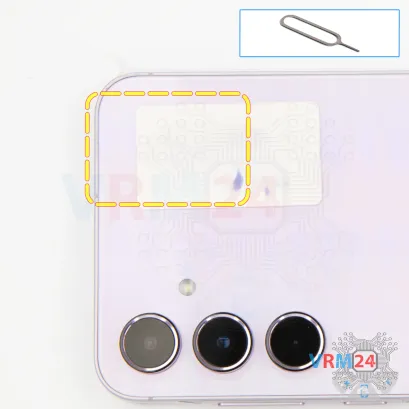
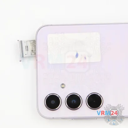

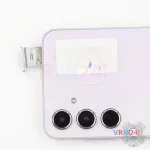

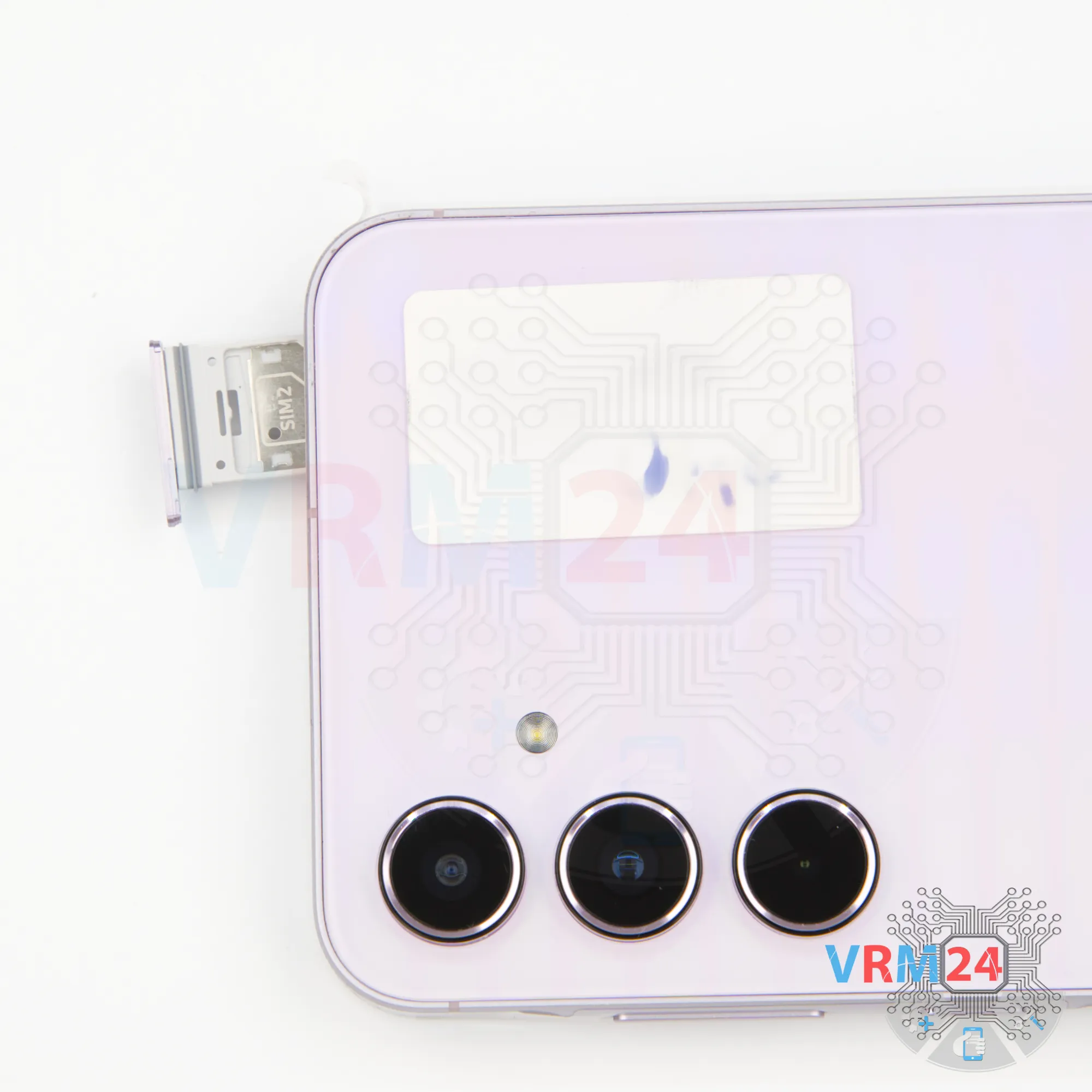
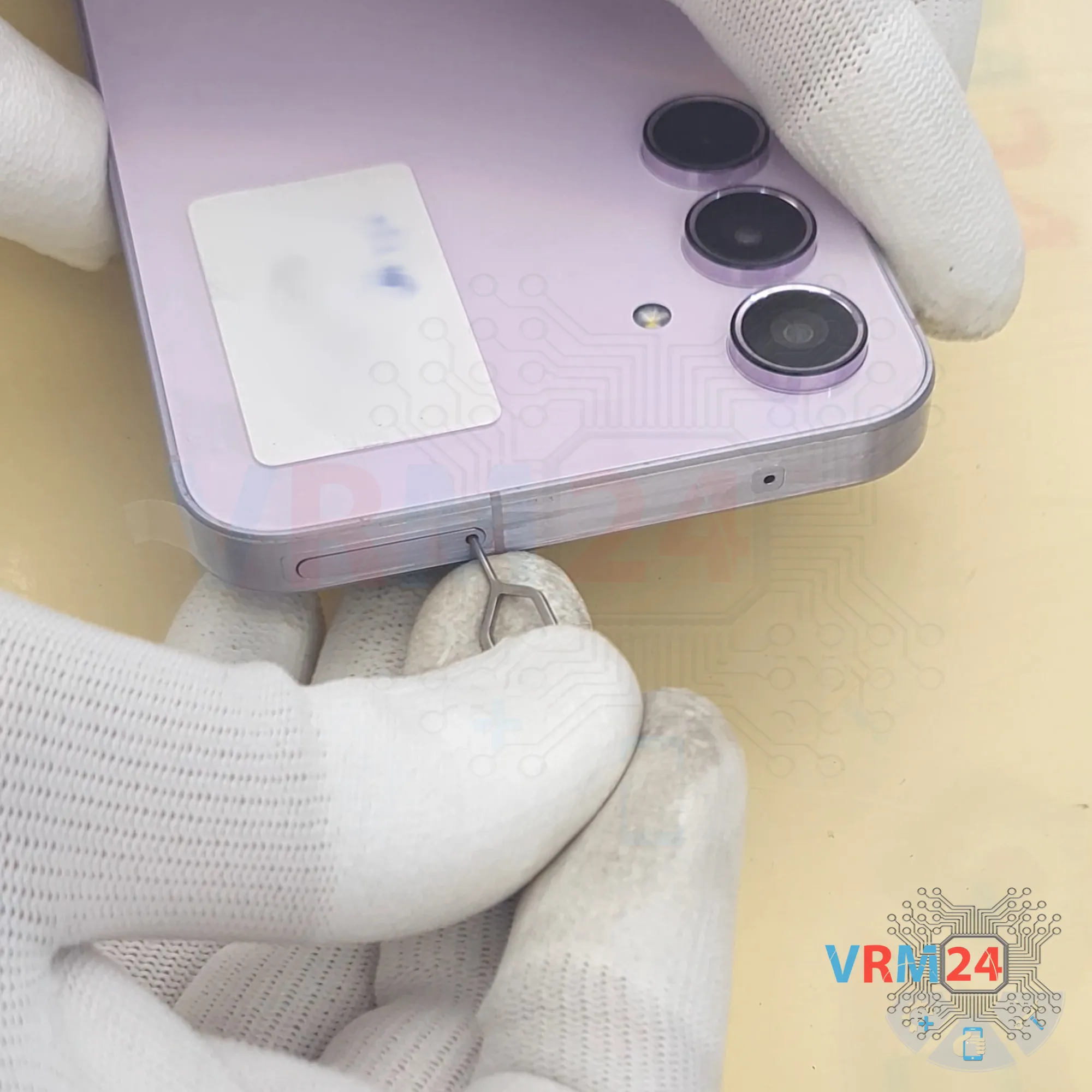
Step 2. Remove the tray
First, as usual, we need to remove the SIM card tray. For this, we use the SIM ejector tool.
Insert it into the hole and gently push out the tray, which is located at the top.

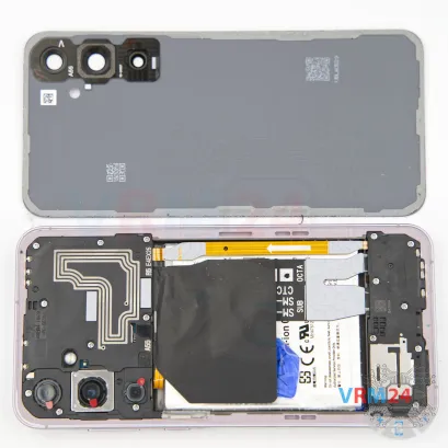
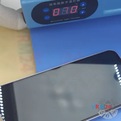
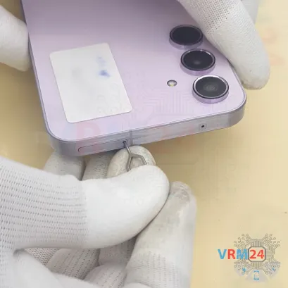
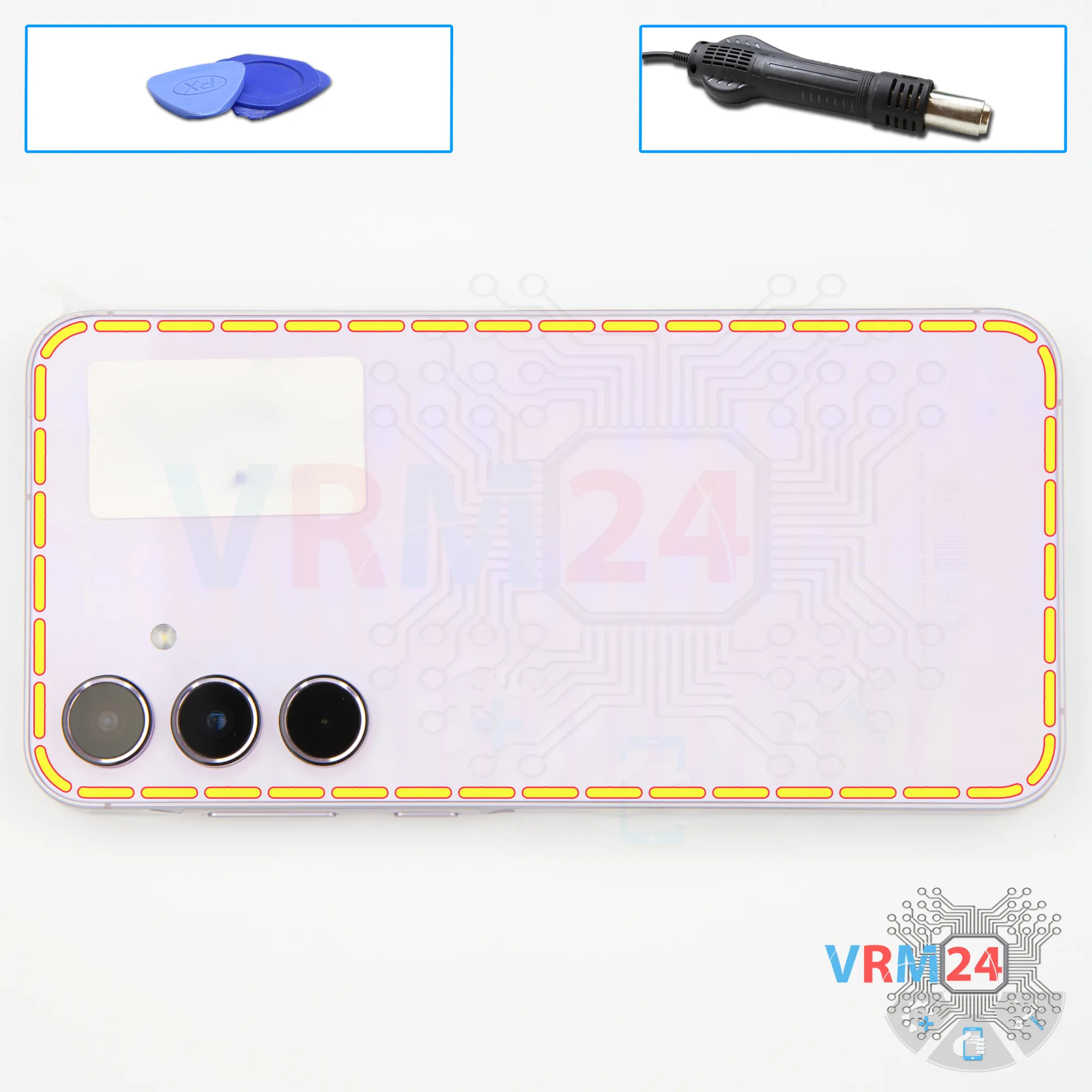
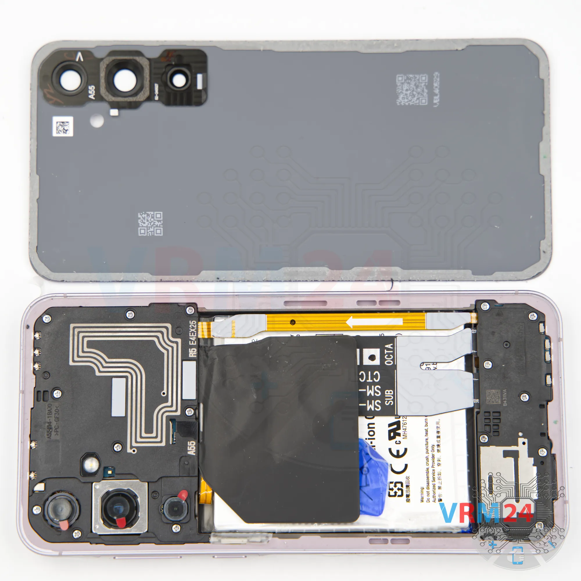
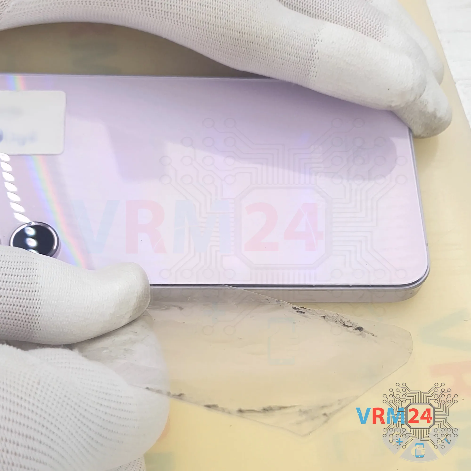
Step 3. Open the back cover
Next, we need to heat the back cover surface to around 70 degrees Celsius or 160 degrees Fahrenheit. We use a heating mat for this, but you can also use a hairdryer.
And after 5 to 7 minutes, we can move on to detaching the back cover.
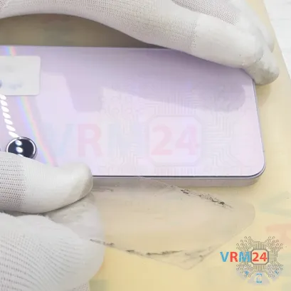
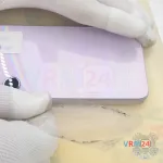
To detach the back cover, we use a thin plastic film. This film can be the protective film from a new display or film from a stationery store. Carefully insert it into the gap between the back cover and the mid-frame, then gently slide it along the edge to cut through the adhesive.
As always, be extra careful around the camera area to avoid accidentally touching the lenses.
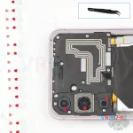
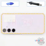
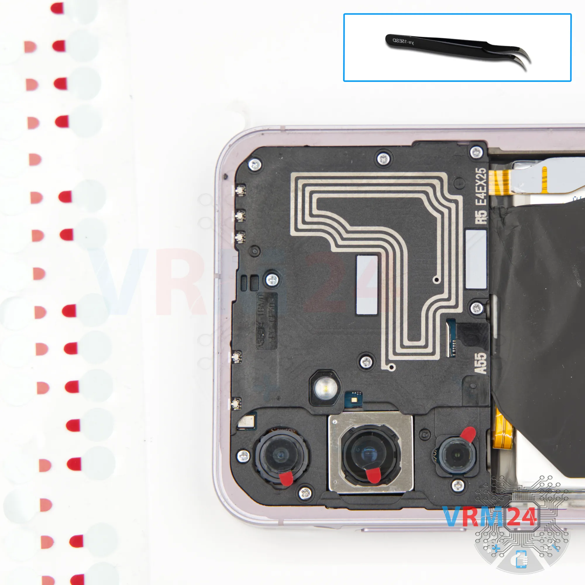
Step 4. Protecting camera lenses
Now it's best to cover the camera lenses. For this, we use a special protective film.
Please note that the film is applied not directly to the lens glass, but to the rim surrounding the camera module.
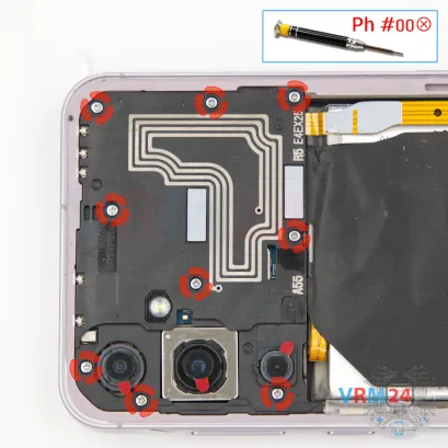


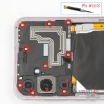
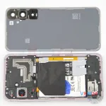
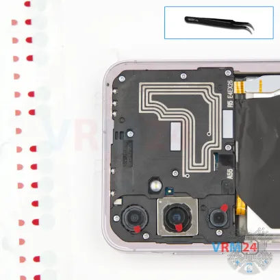
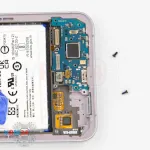
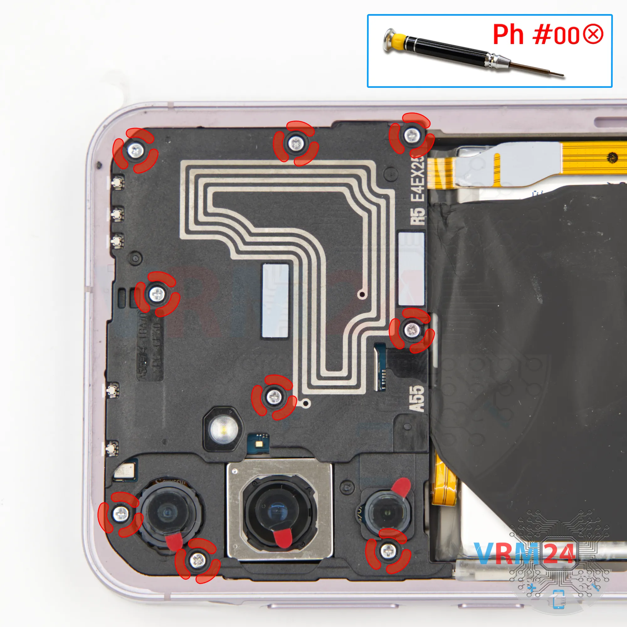
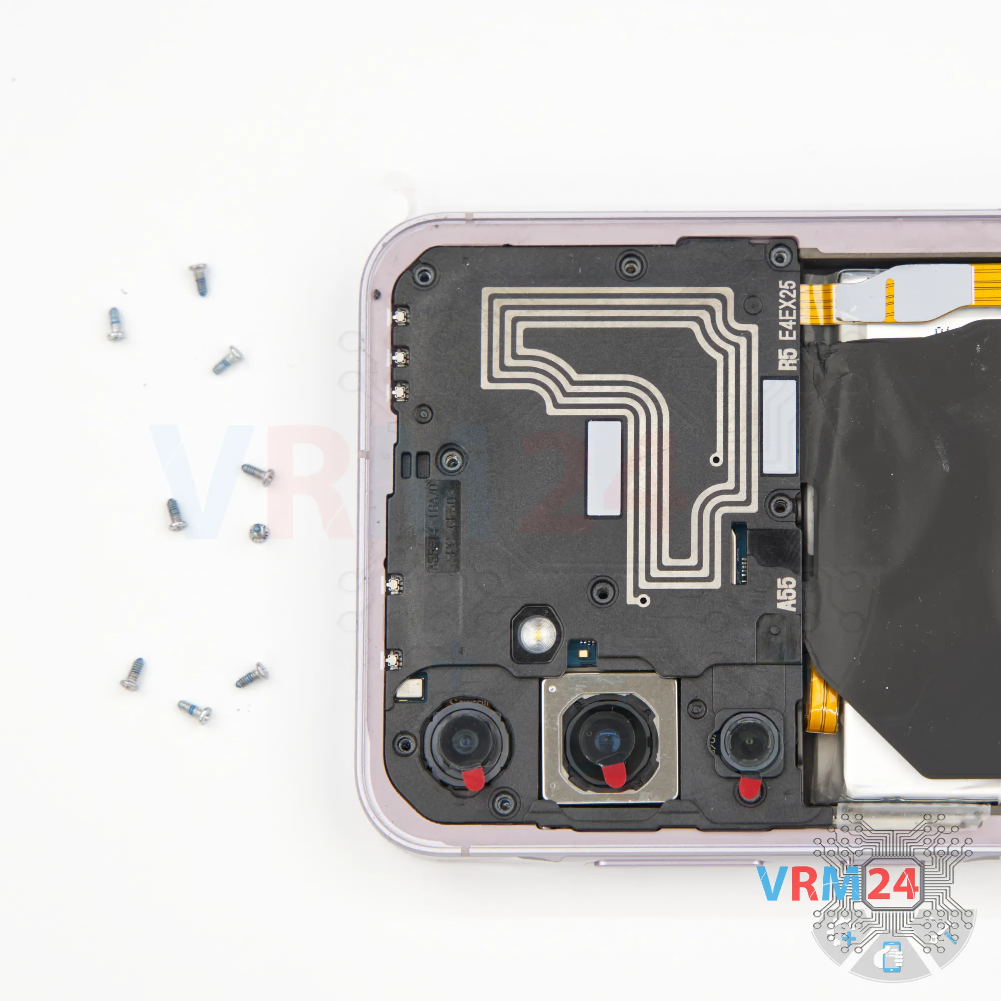
Step 5. Unscrew the screws
We move on to unscrewing the nine top screws. For this, we use a 1.5mm cross-head screwdriver or a Phillips #000.
It's best to place the screws on a special surface in a specific order, just in case.


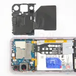
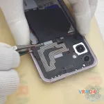
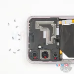
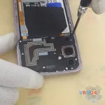
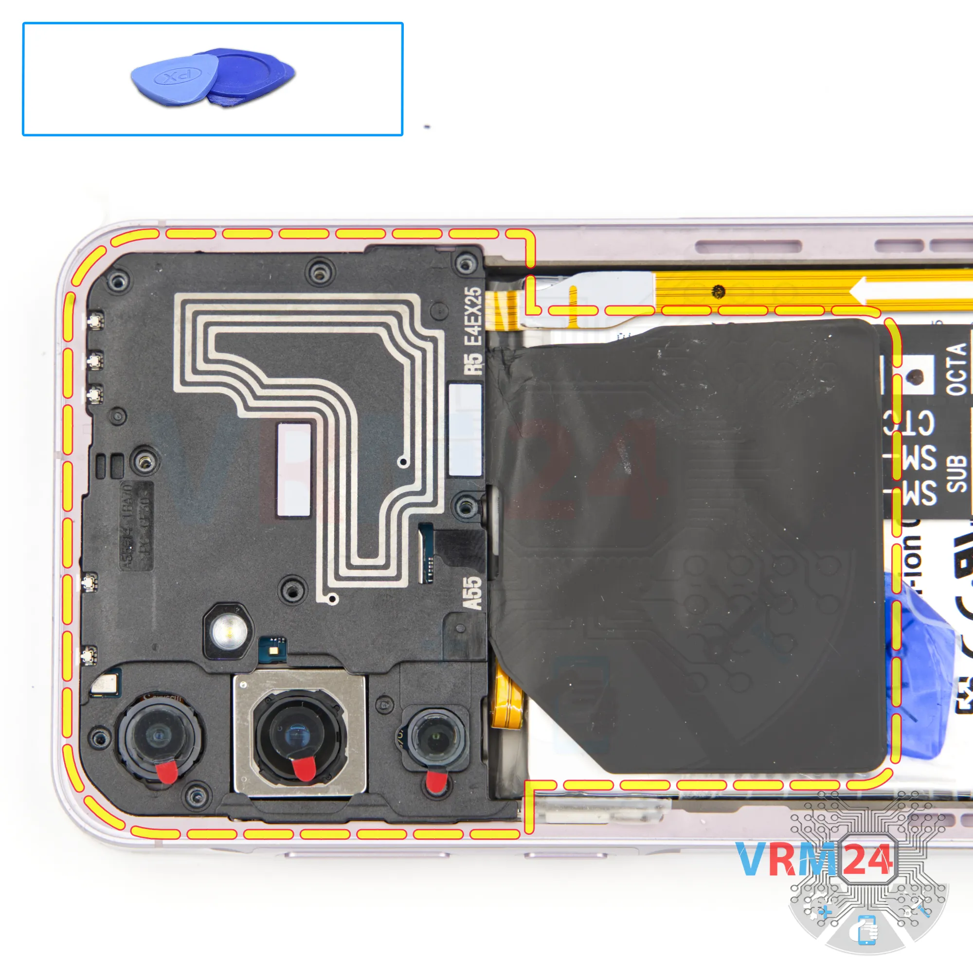
Step 6. Open the cover
So, after removing the screws, use a non-metallic tool to pry off the top cover.
Why non-metallic? To avoid short-circuiting anything on the motherboard.
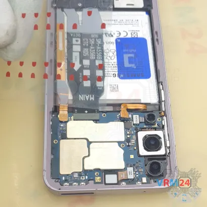
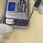
Step 7. Disconnect the battery connector
We also use a non-metallic tool to disconnect the battery connector.
ℹ️️ Samsung Galaxy A55 SM-A556 model has a battery EB-BA546ABY with a capacity of 4905 mAh (also known as a rechargeable battery).

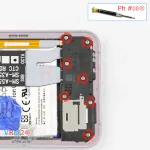
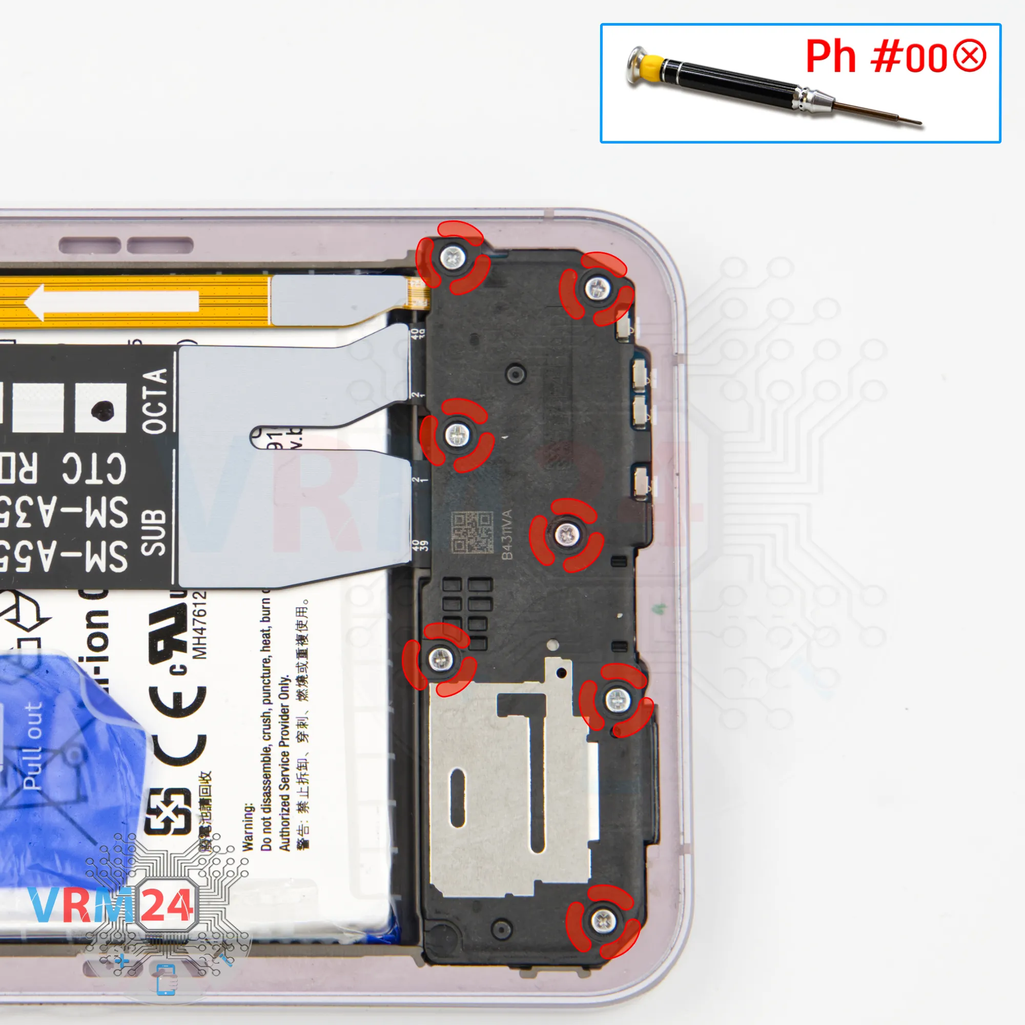
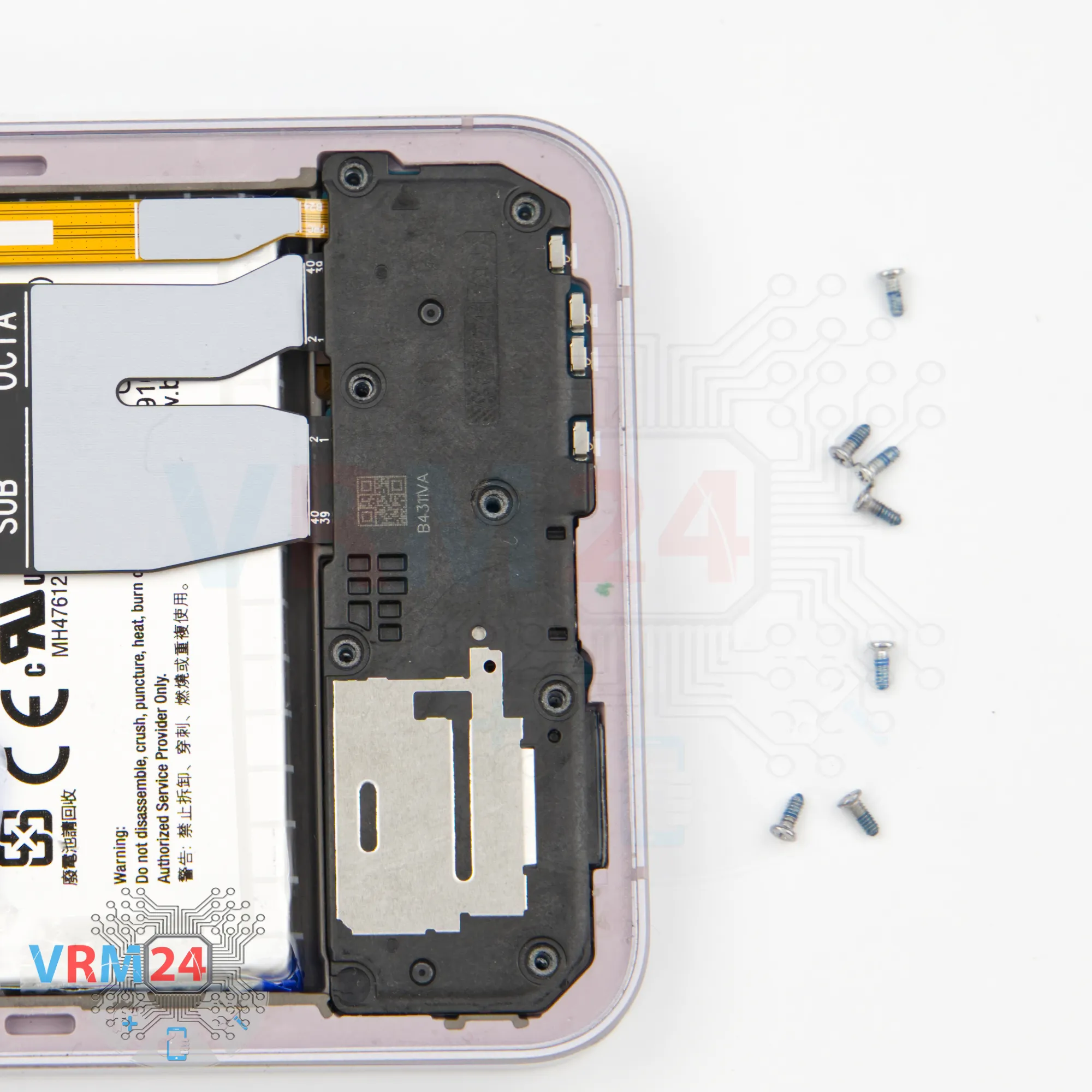
Step 8. Unscrew the screws
We move on to unscrewing the screws in the bottom section. For this, we also use a 1.5mm cross-head screwdriver (PH #000).
It’s best to keep these screws separate from the previous ones.


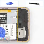

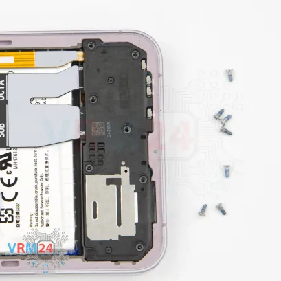
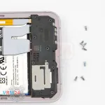
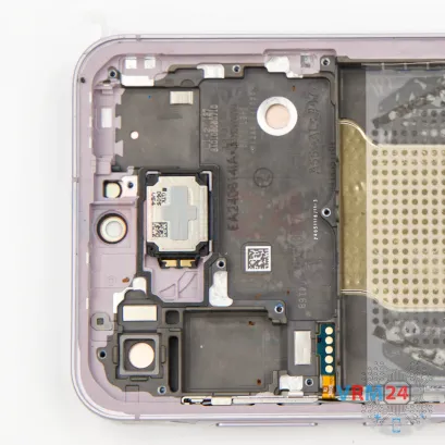
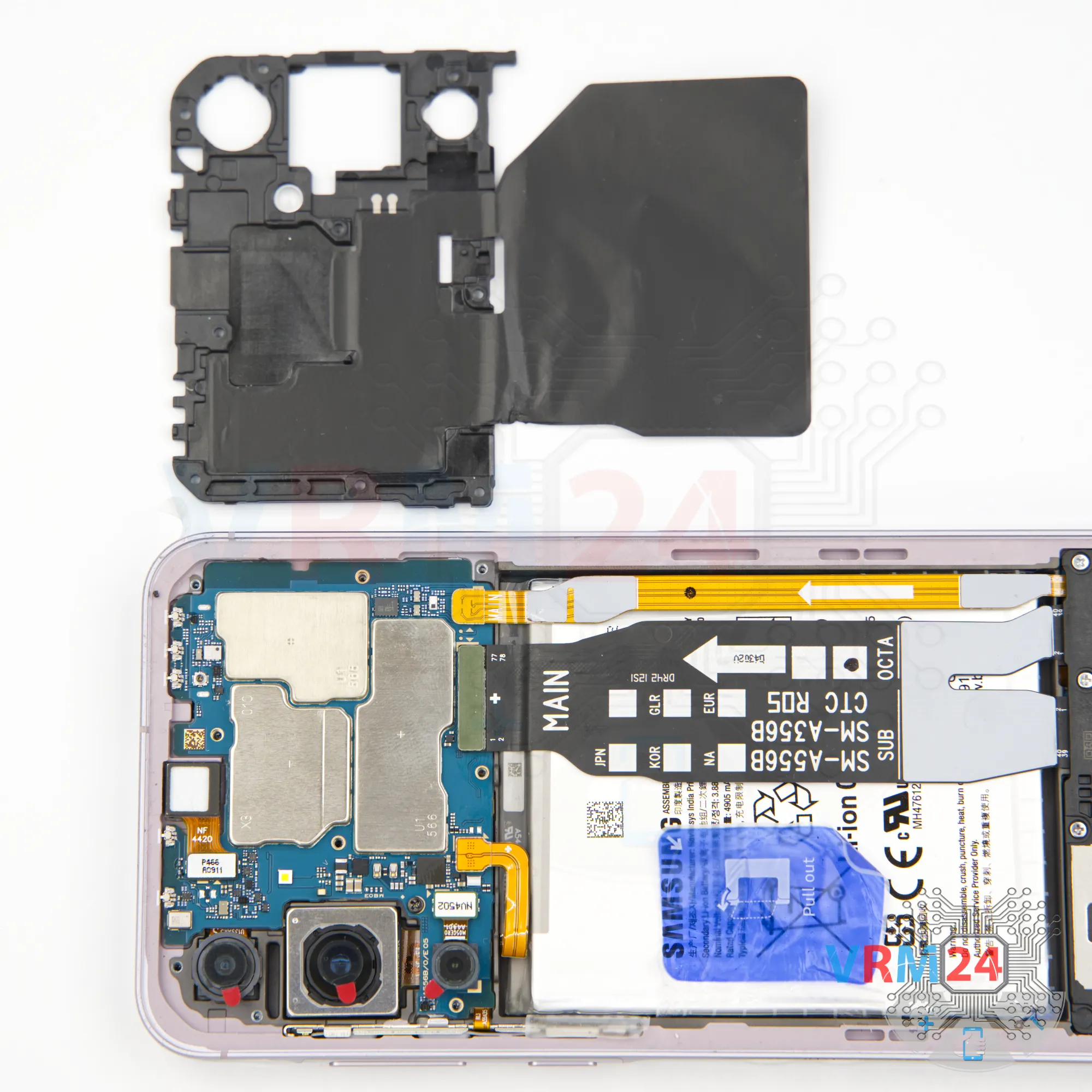
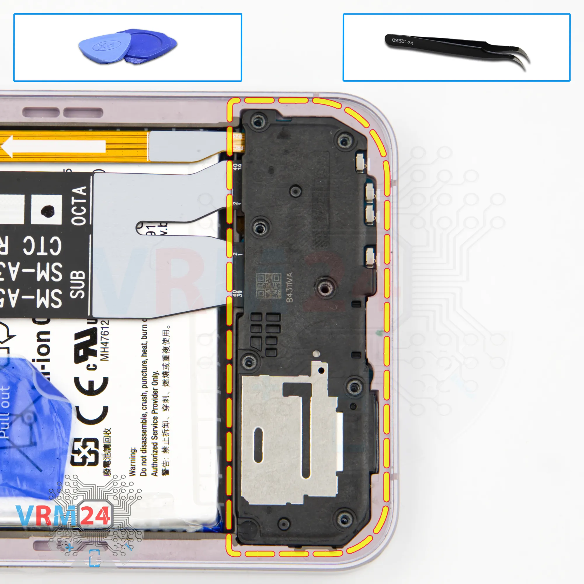
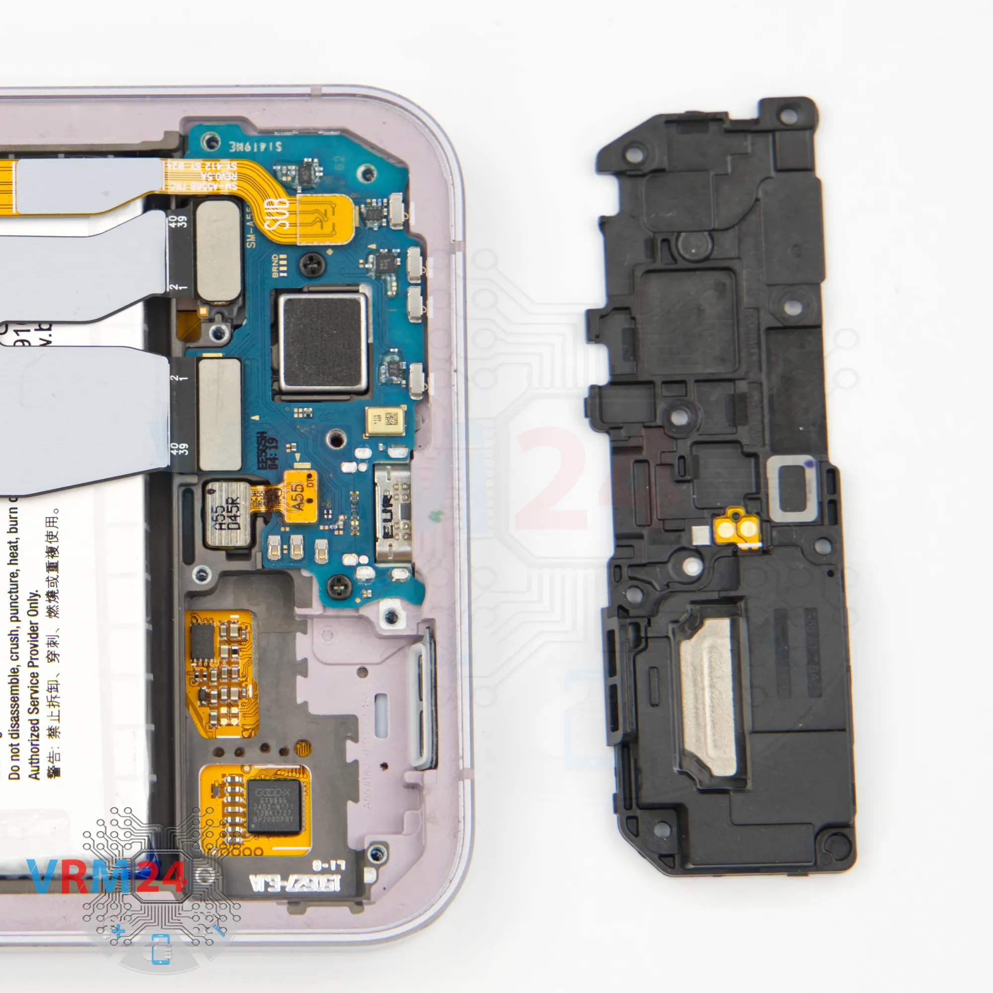
Step 9. Remove the loudspeaker
After removing the screws, we can detach the bottom cover along with the speaker.
Carefully pry it up at the designated spot, lift gently, and remove the cover that contains the speaker.


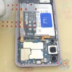
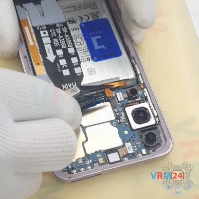
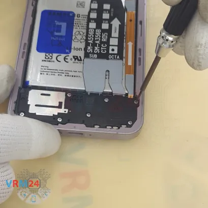
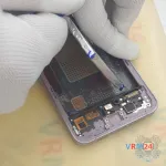
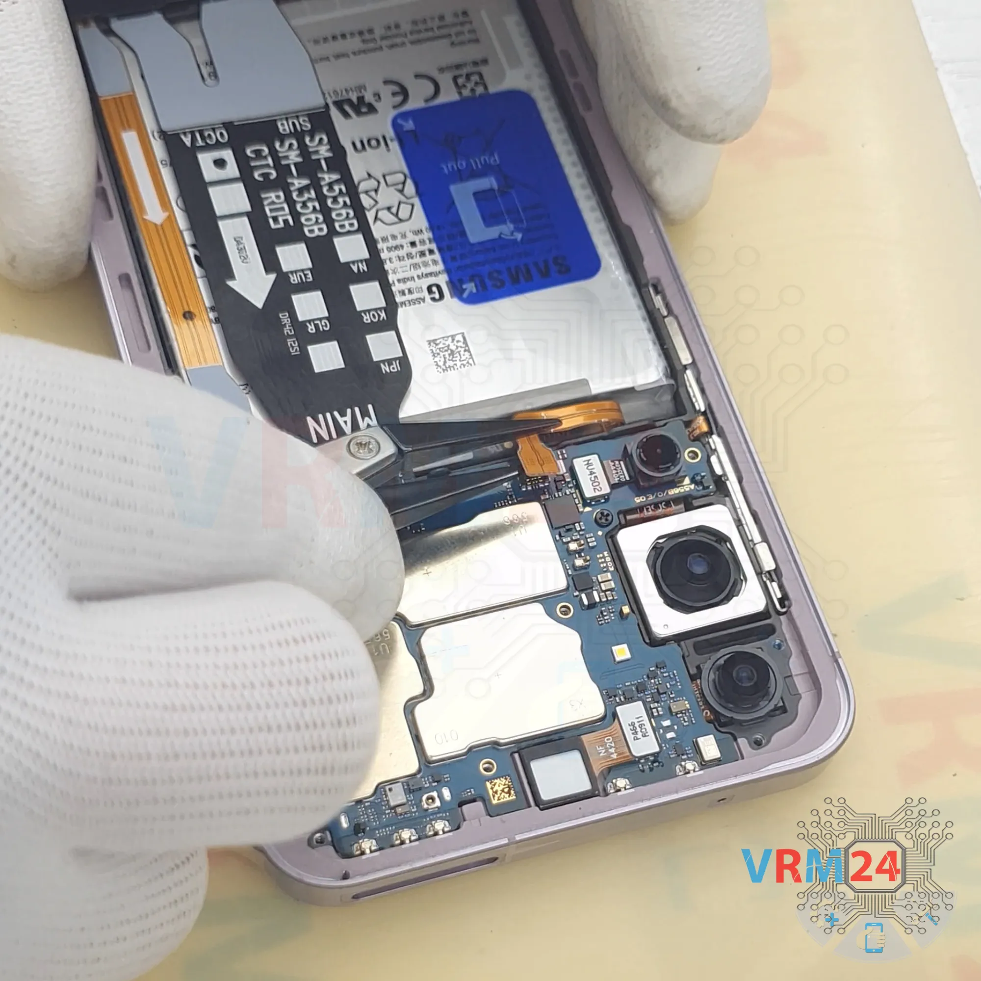
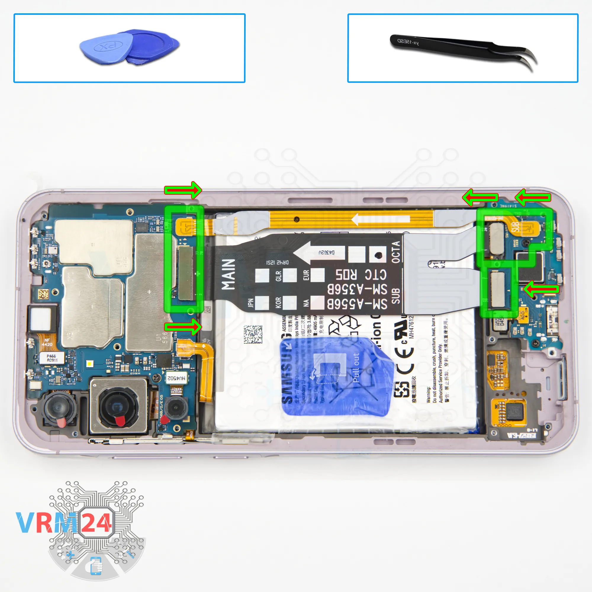
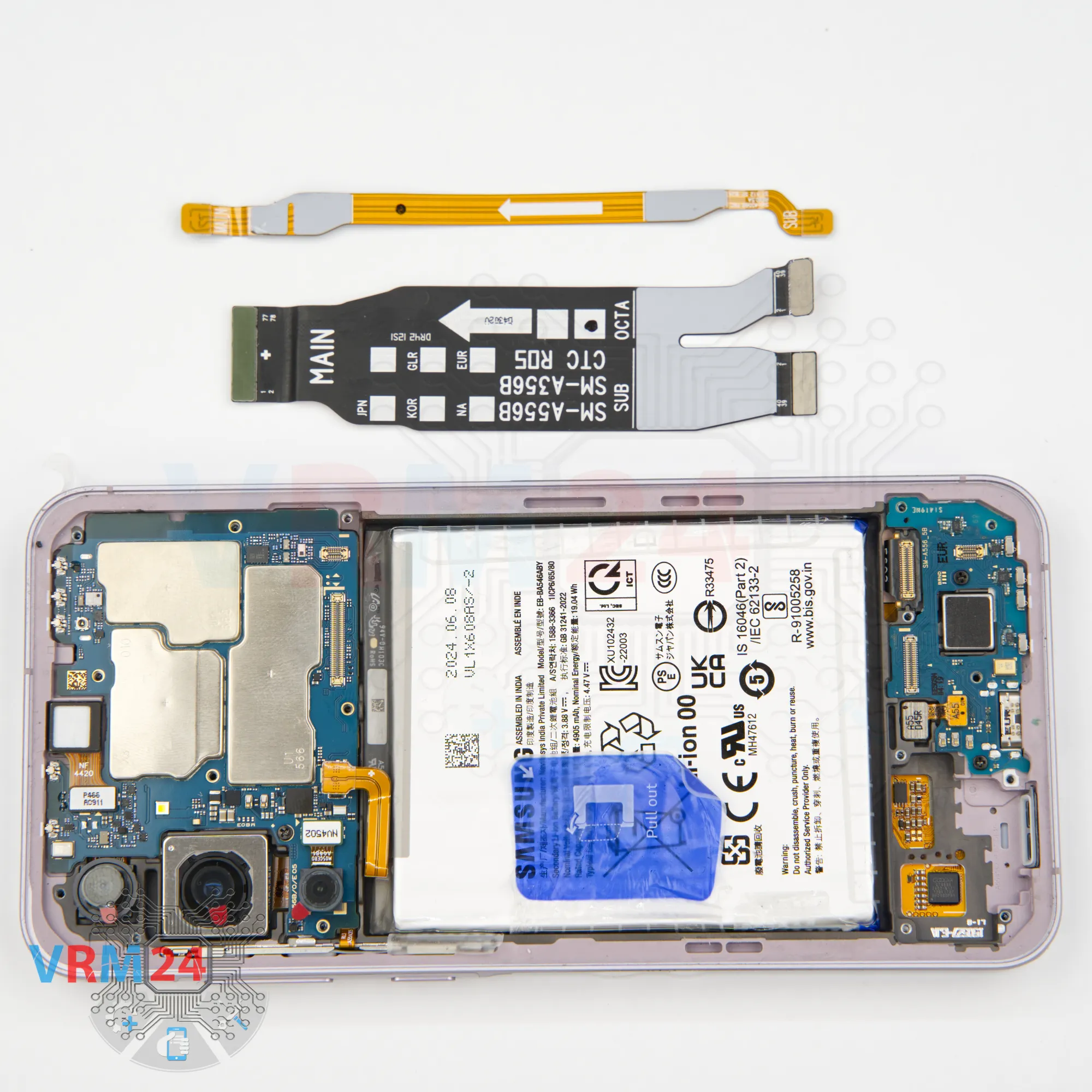
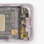
Step 10. Remove the interconnect cables
Next, we disconnect the antenna and the inter-board flex cable connectors.
Disconnect all connectors and move the inter-board cables aside.
⚠️️ Be careful when removing the cables from the connectors, the cables are pretty thin, and it is easy enough to break them or damage the contact tracks inside.
ℹ️️ An arrow on the FFC cable (flexible flat cable) indicates its correct position.
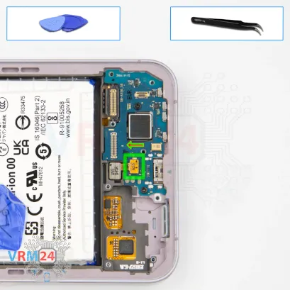


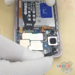
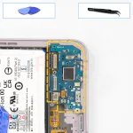
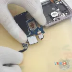
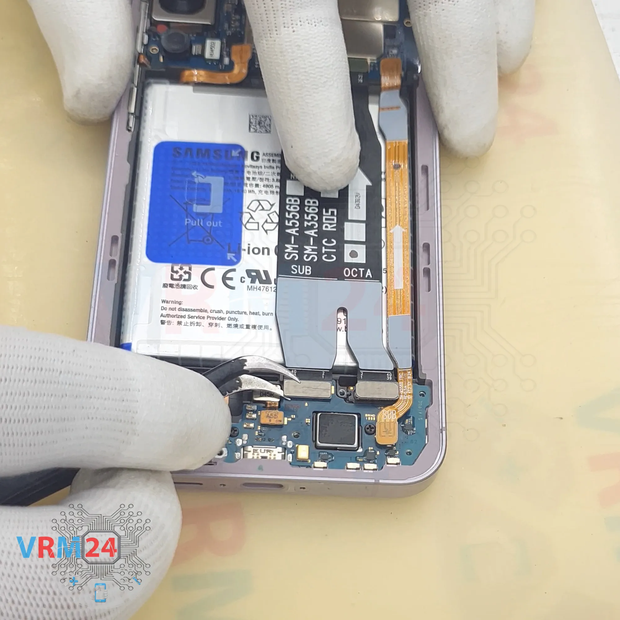
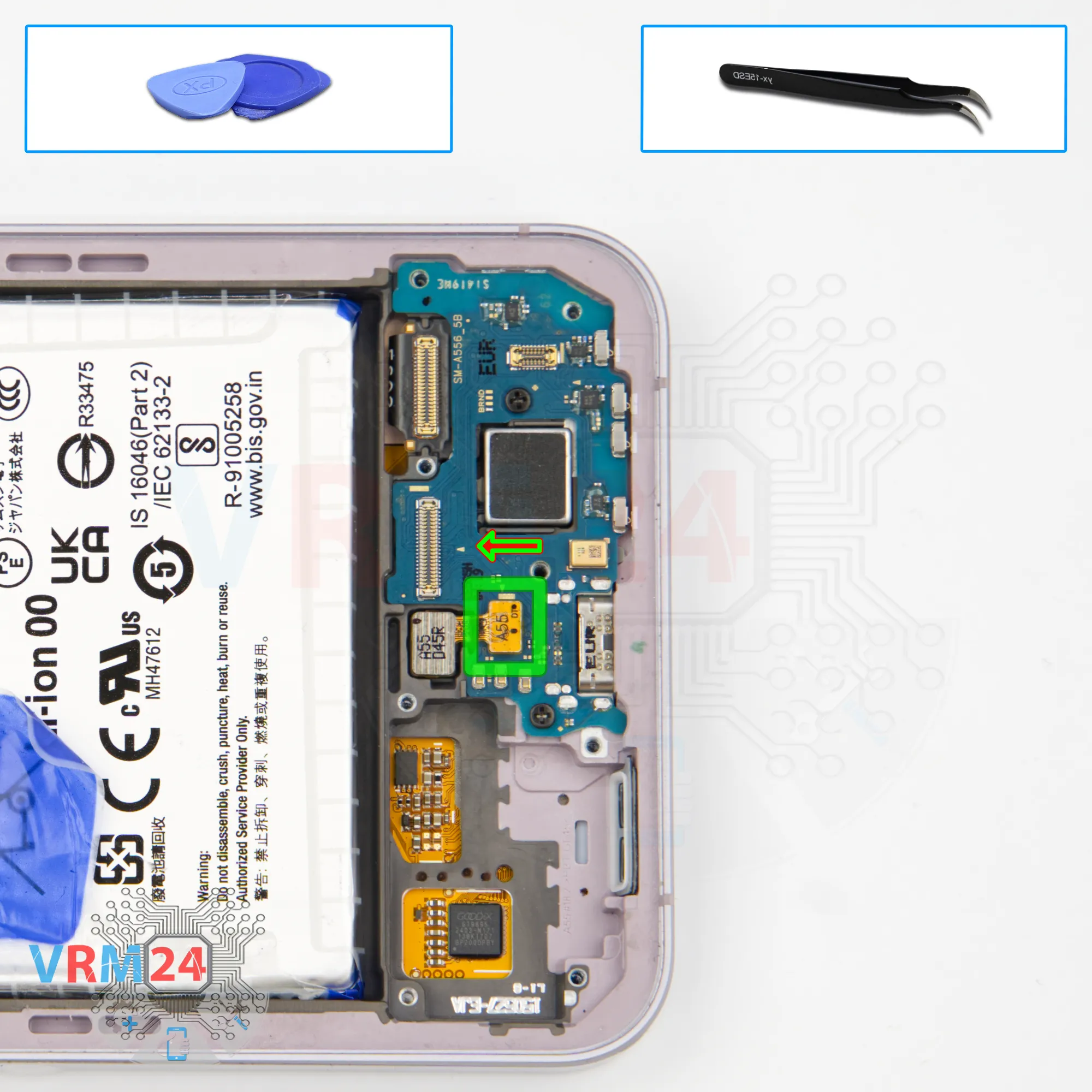
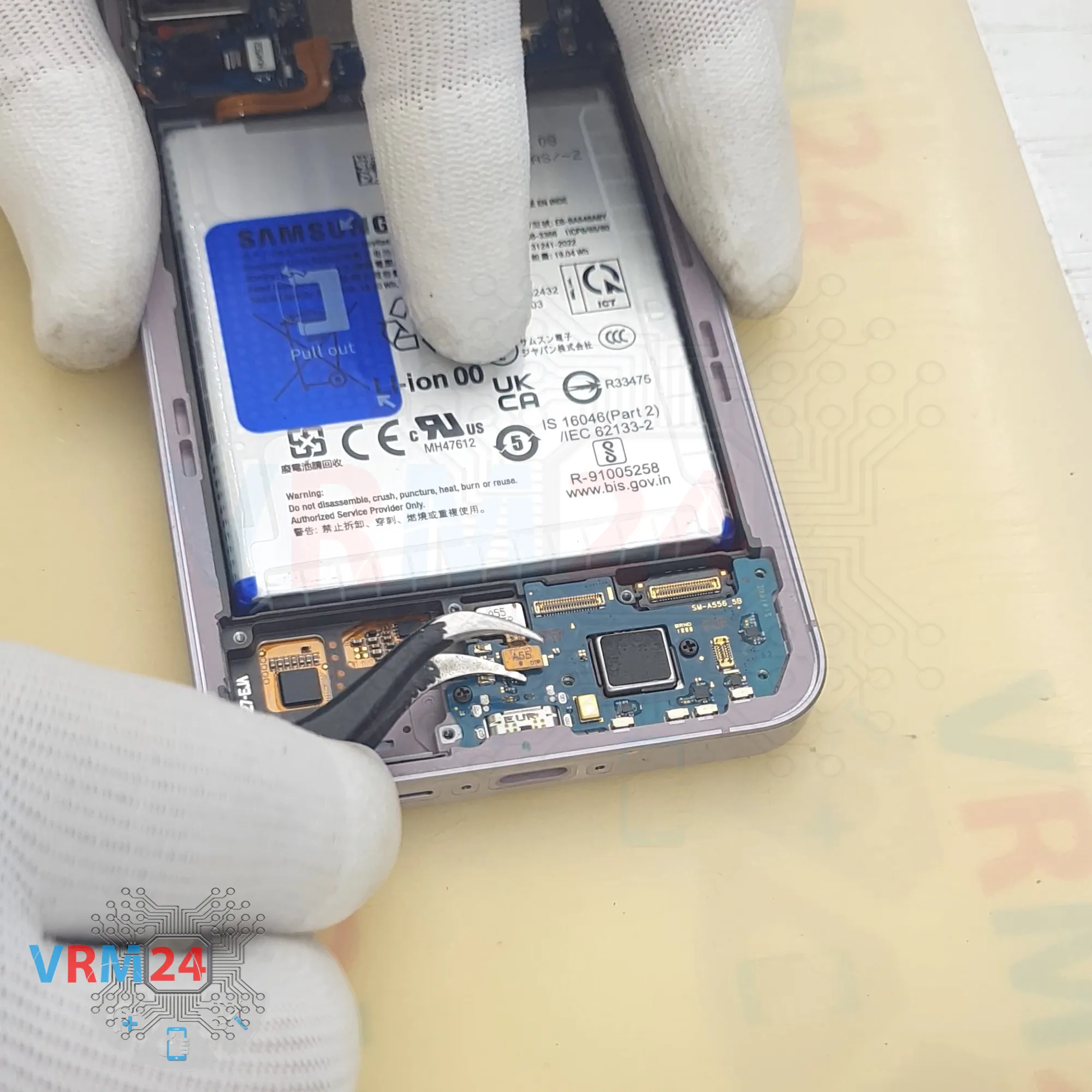
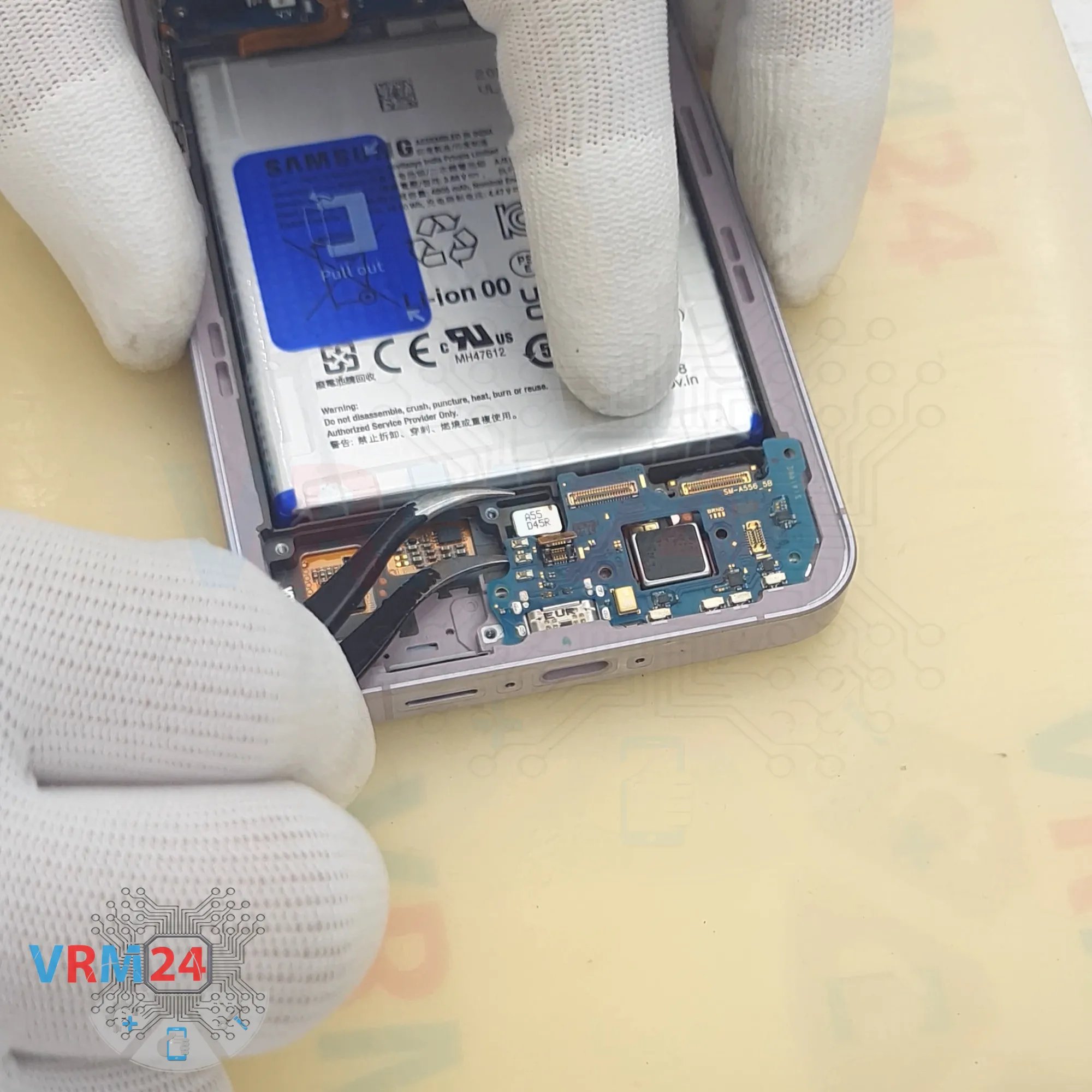
Step 11. Disconnect the connector
We disconnect the fingerprint sensor cable connector on the sub-board.
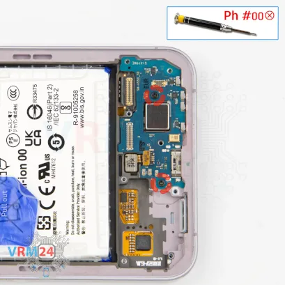


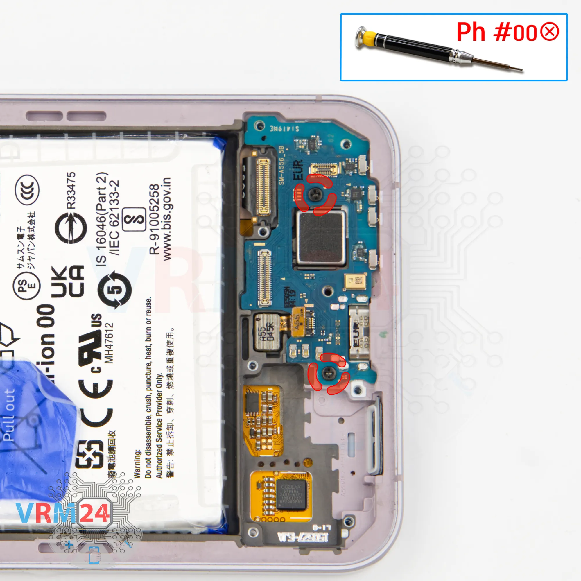
Step 12. Unscrew the screws
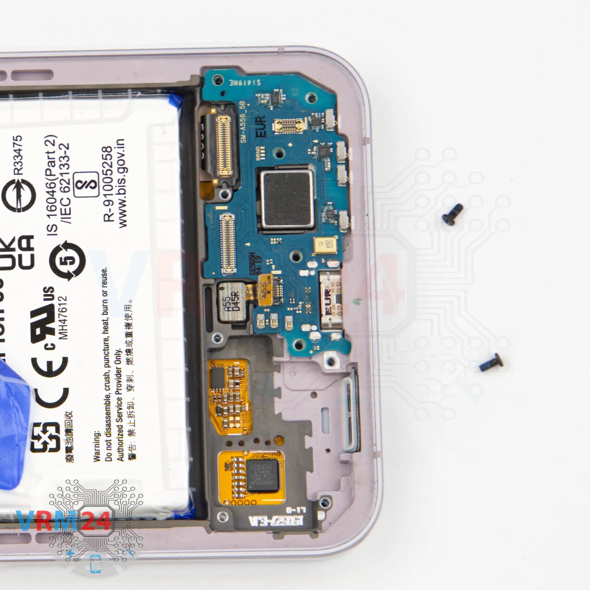
Next, we unscrew the two screws securing the sub-board.
These screws are different from the previous ones—they’re smaller and black. Be sure to keep them separate from the others.
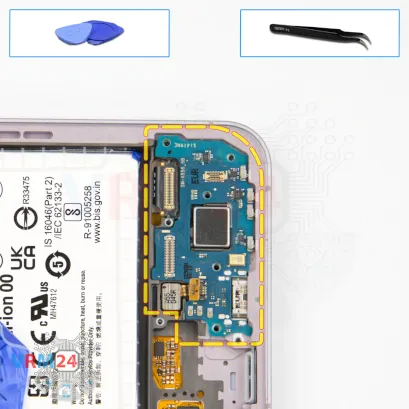
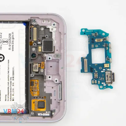
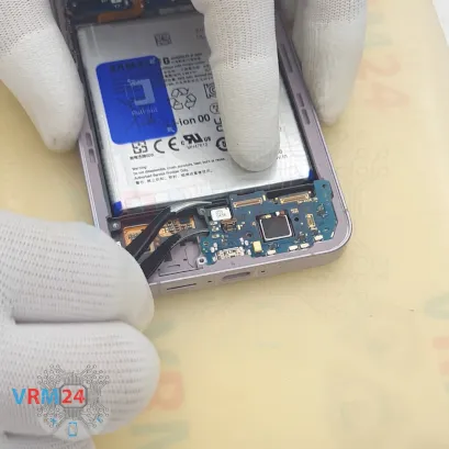
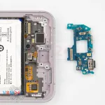
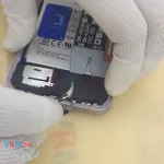
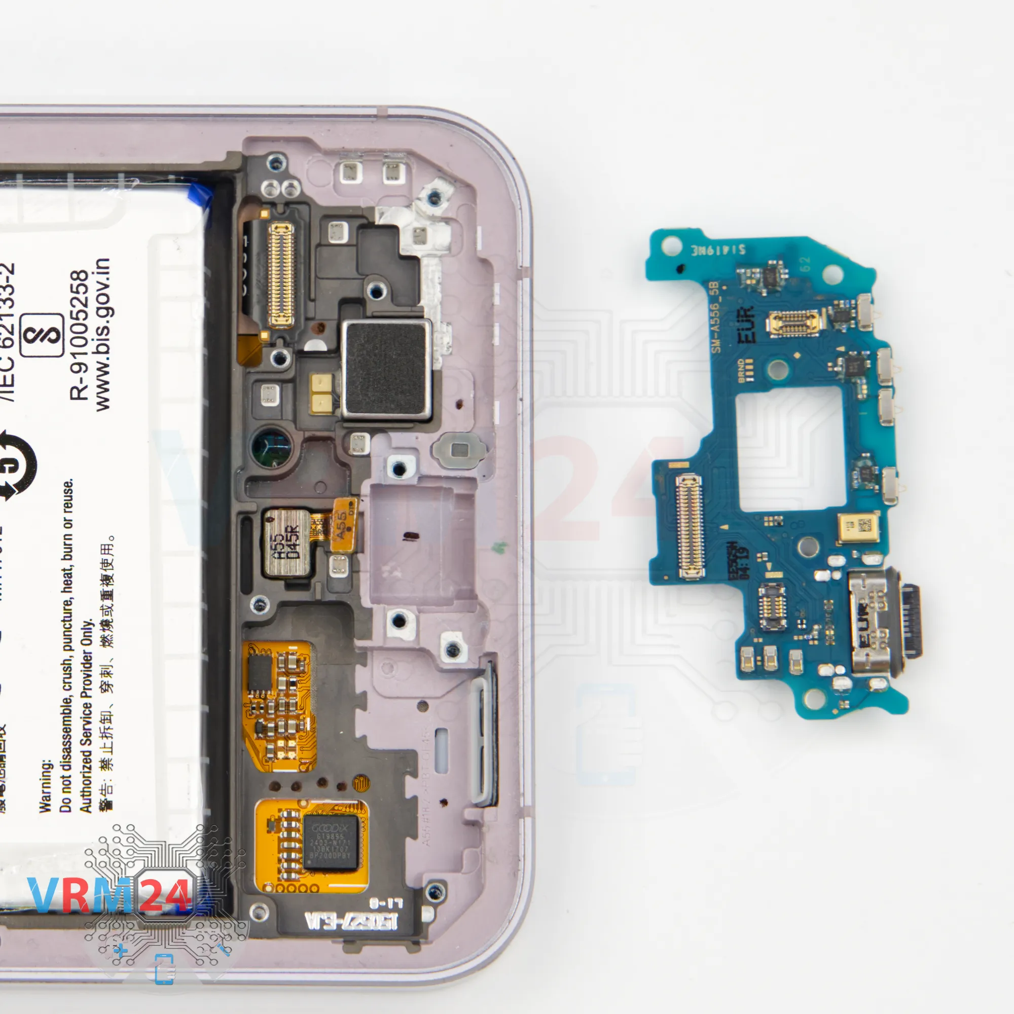
Step 13. Remove the sub-board
Now we can remove the sub-board. Lift it gently, slide it out, and take care not to damage the fingerprint sensor flex cable.
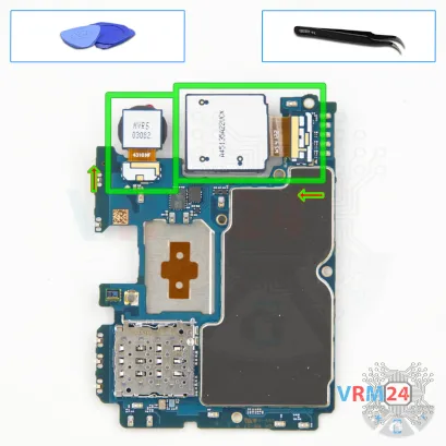
The sub-board contains the charging port, microphone, and other components on its reverse side.
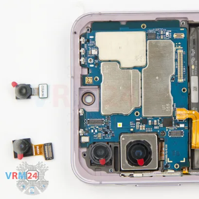

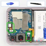
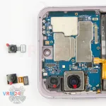

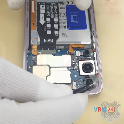
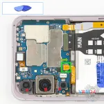
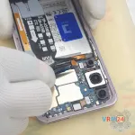
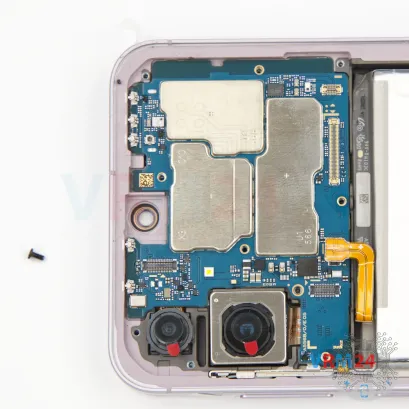
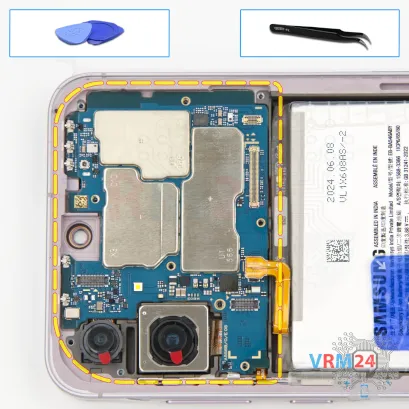
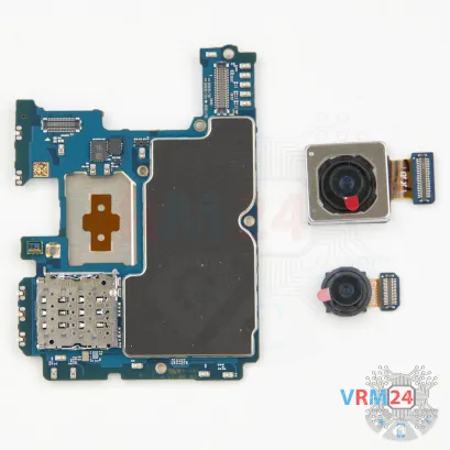
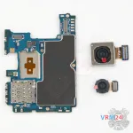
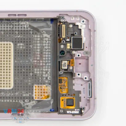
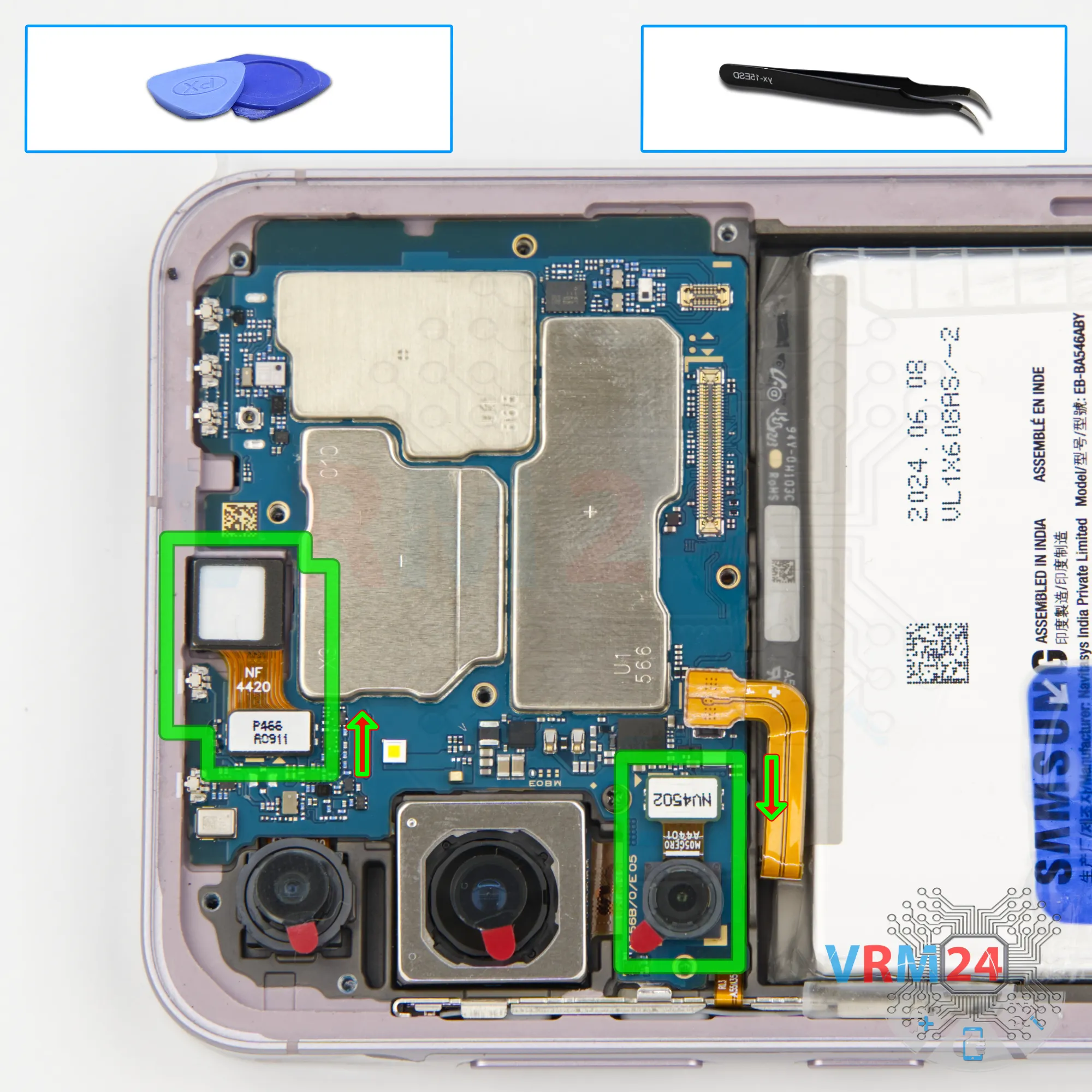
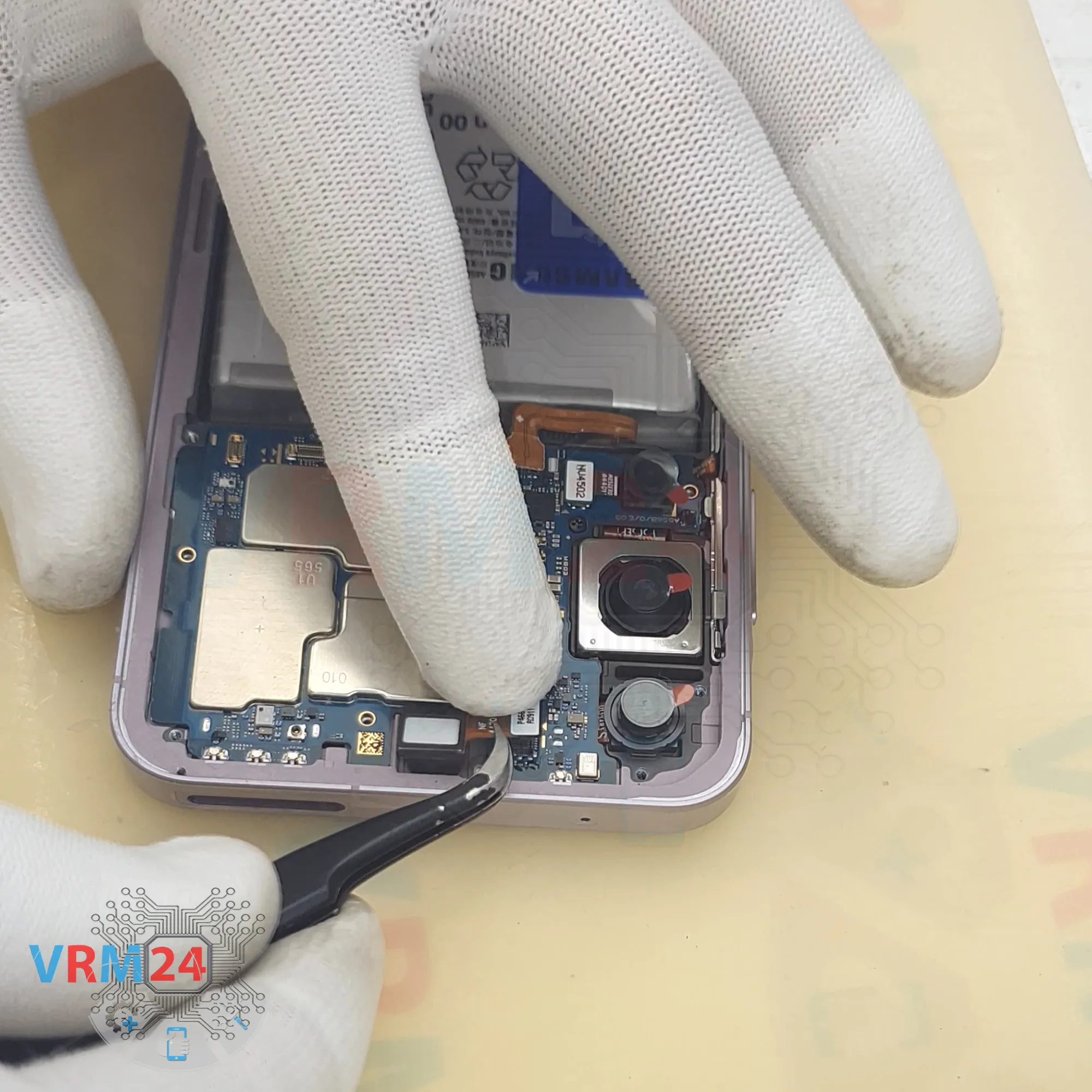
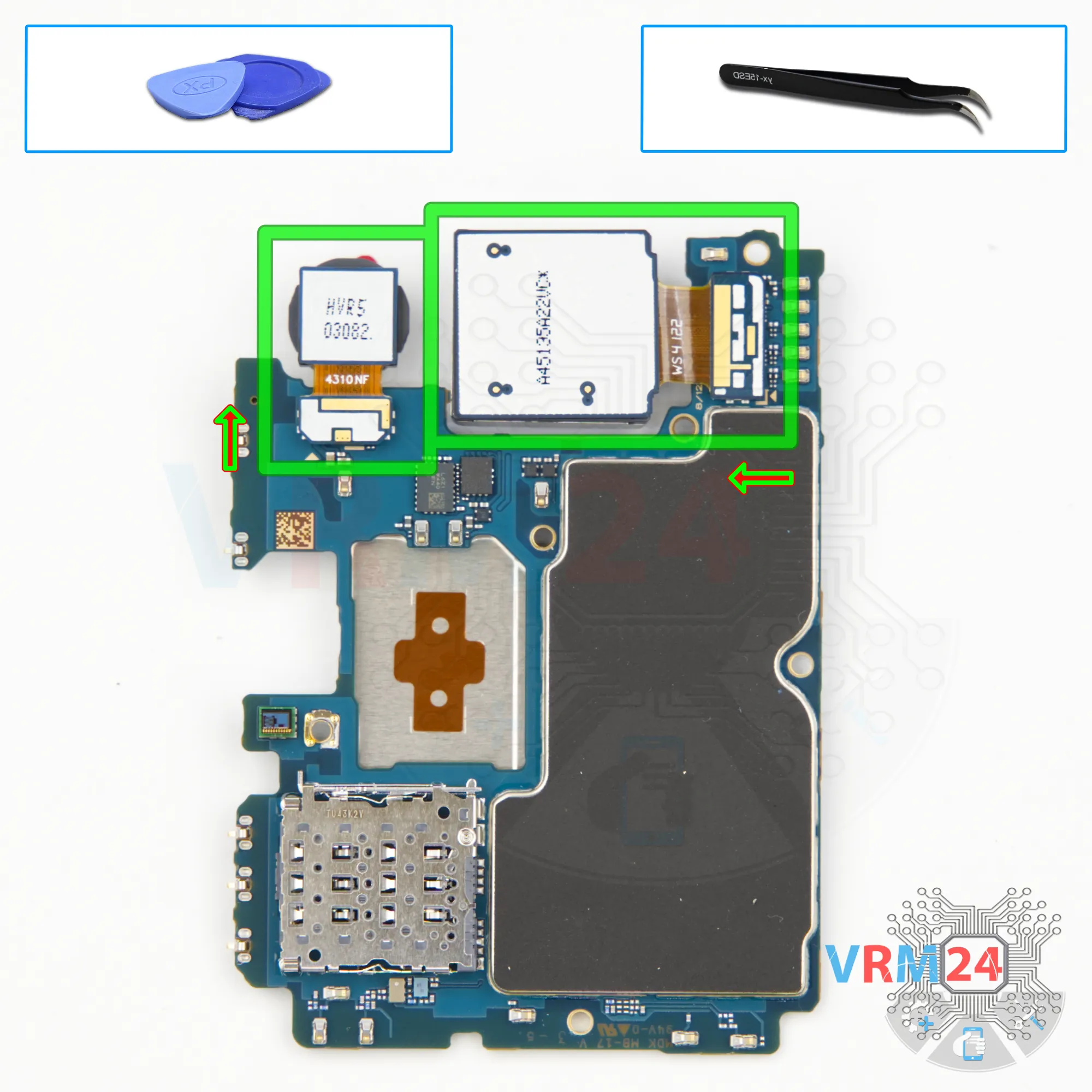
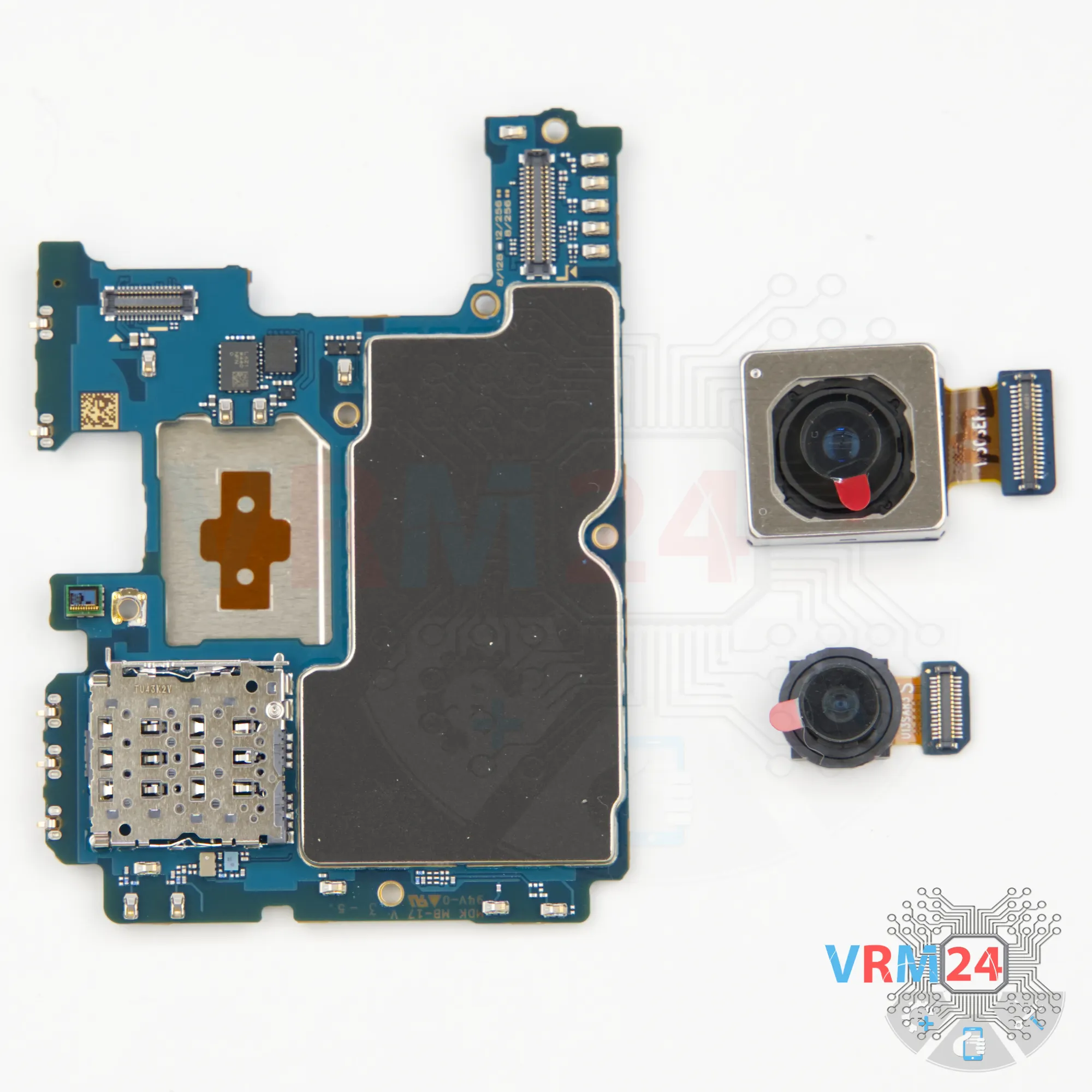
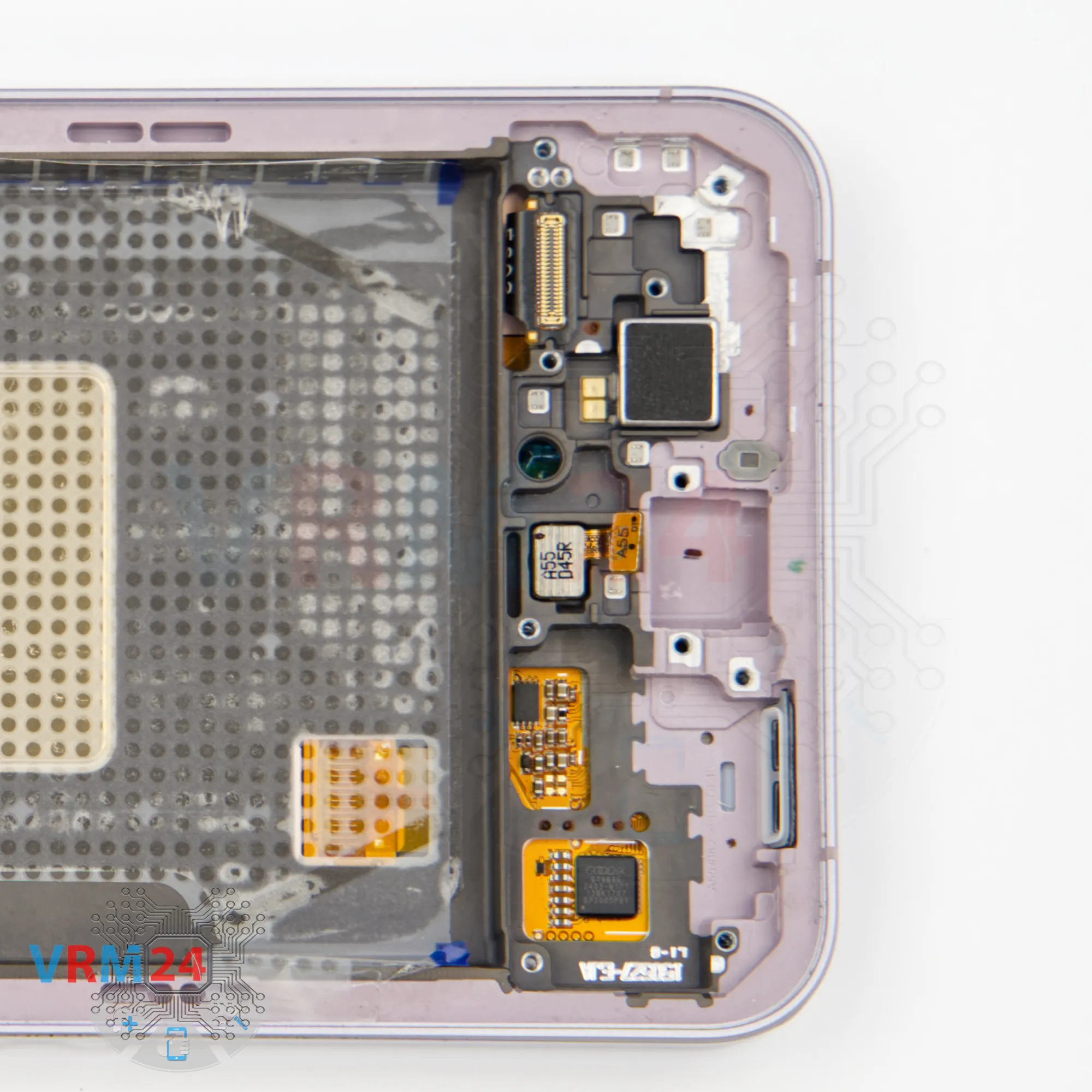
Step 14. Remove the cameras
Now, moving to the top section: here we can disconnect the front-facing camera and the small rear camera. Detach them carefully.
It’s also a good idea to cover the front camera lens to prevent dust from settling on it. Then, set the cameras aside.
The connectors for the other rear cameras are standard for this series — located on the back side. We will disconnect those later.

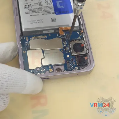

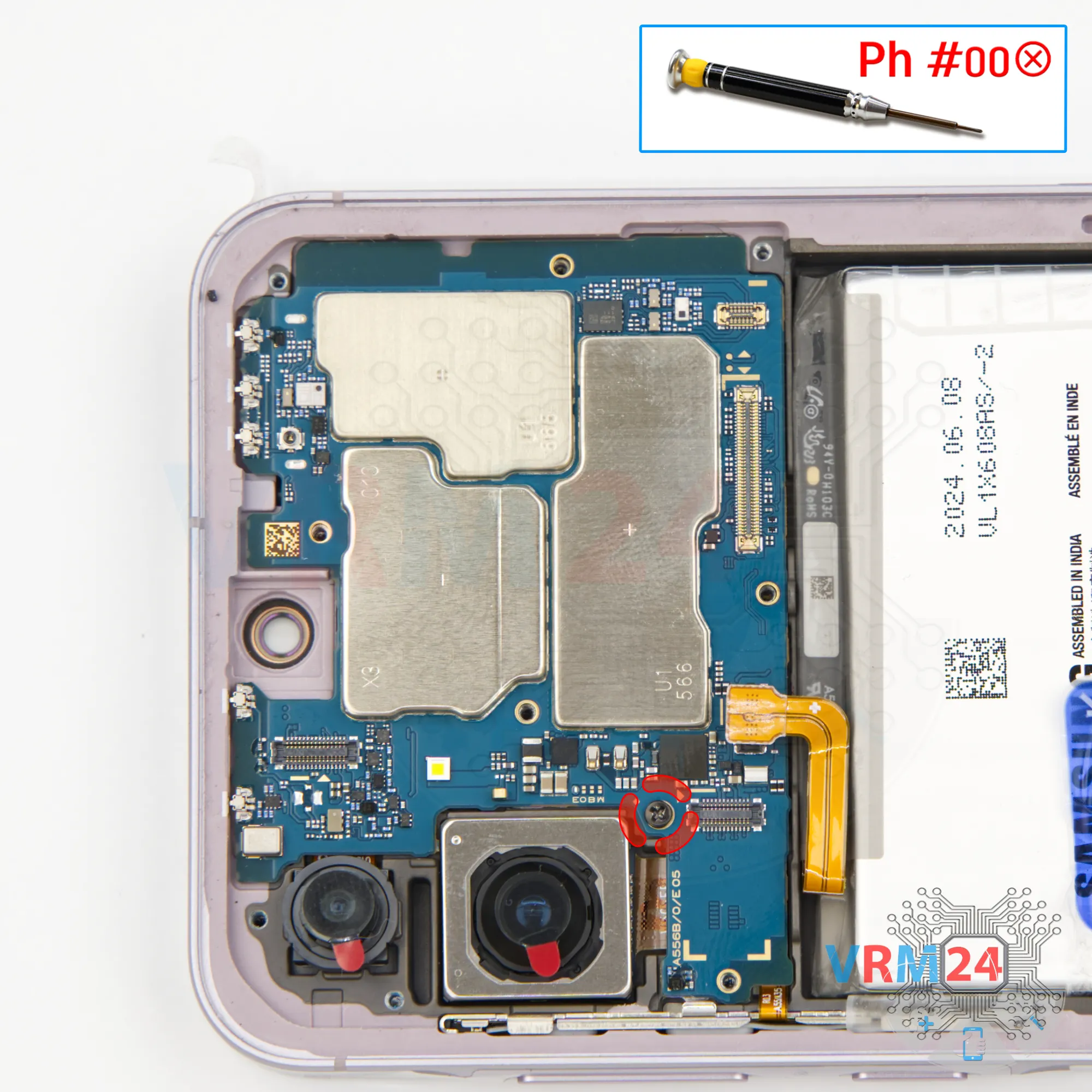
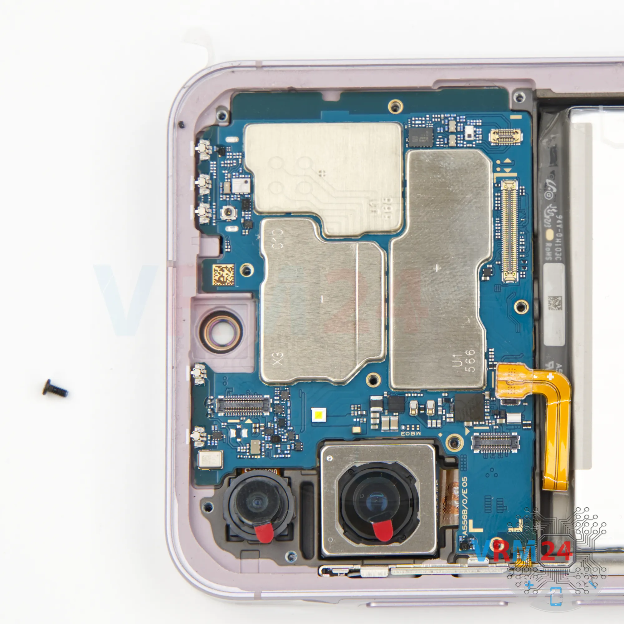
Step 15. Unscrew one screw
Now, remove the single screw securing the motherboard. Use a 1.5mm Phillips screwdriver for this.


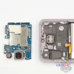

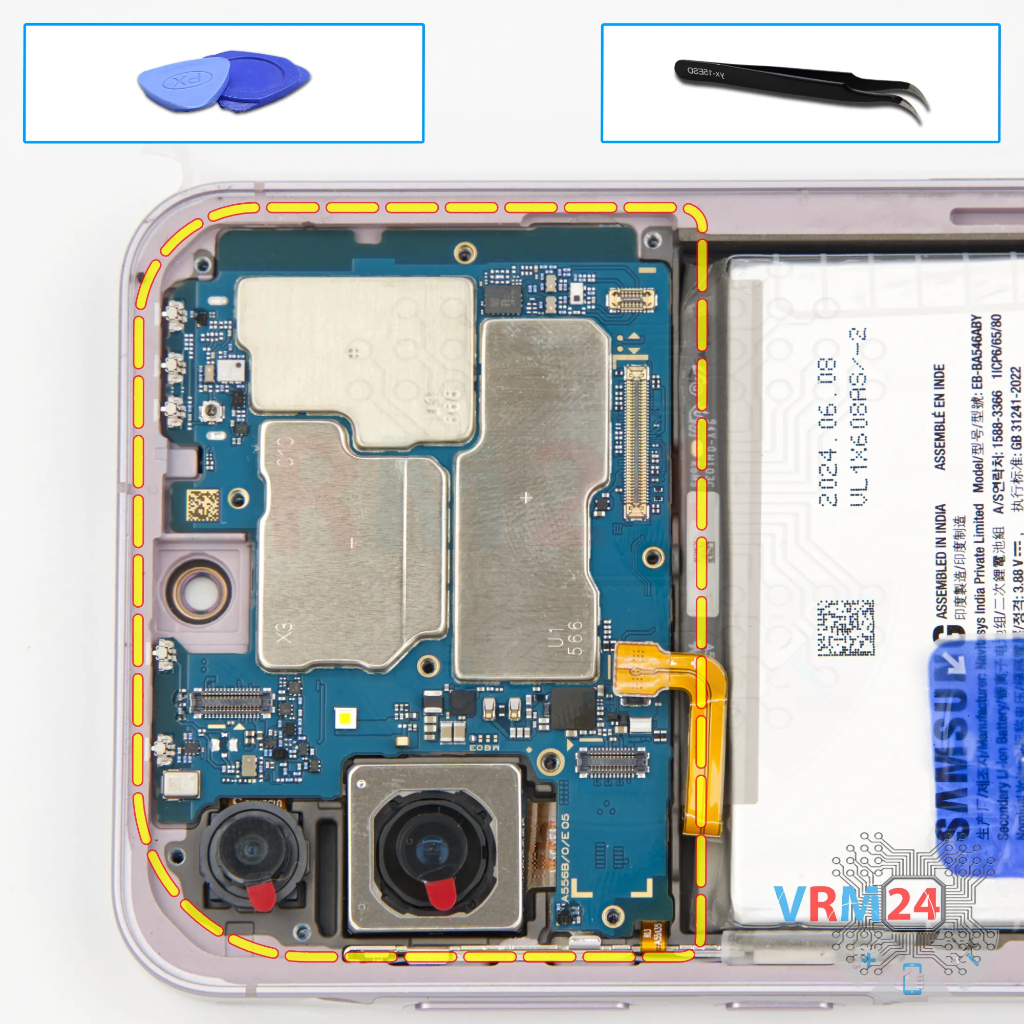
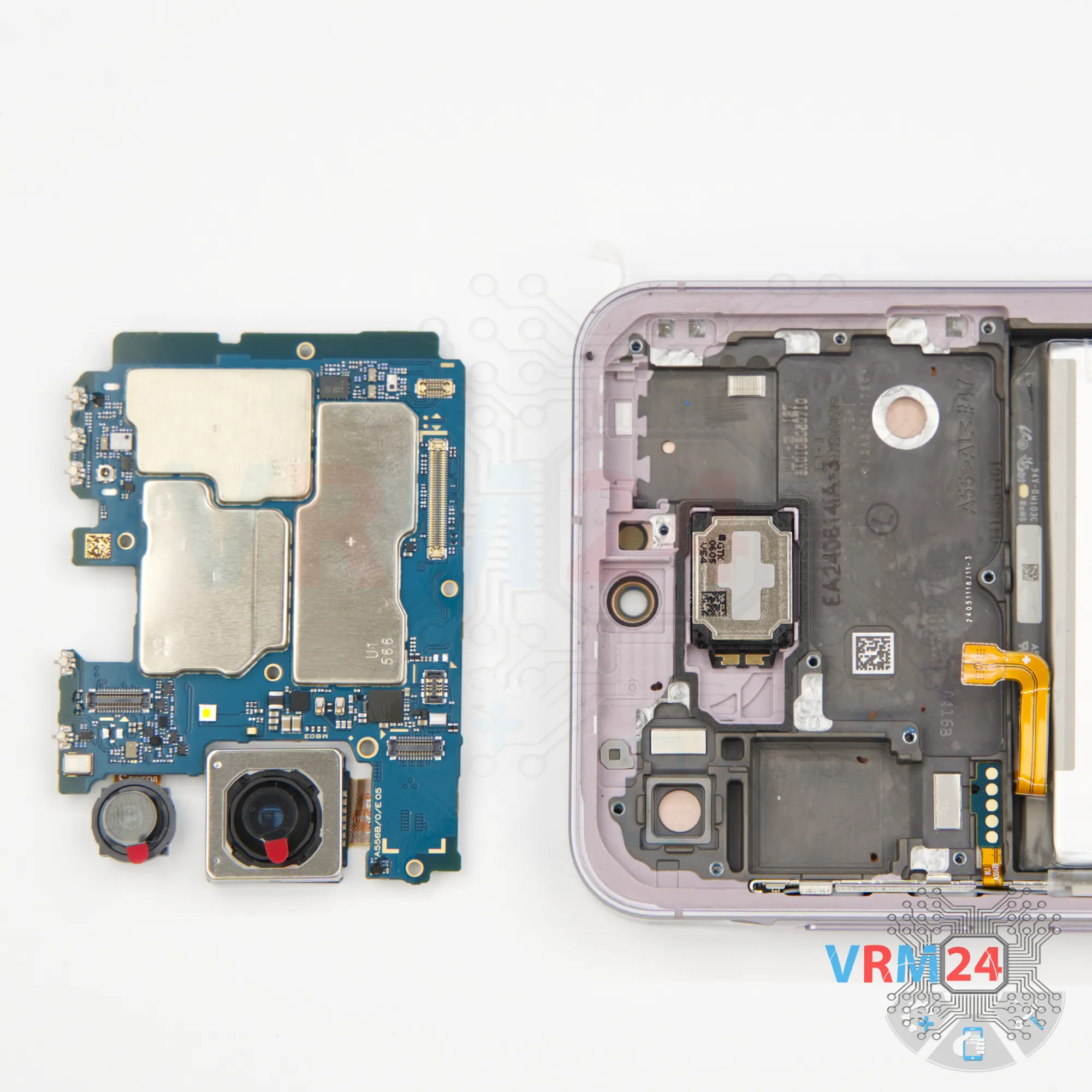
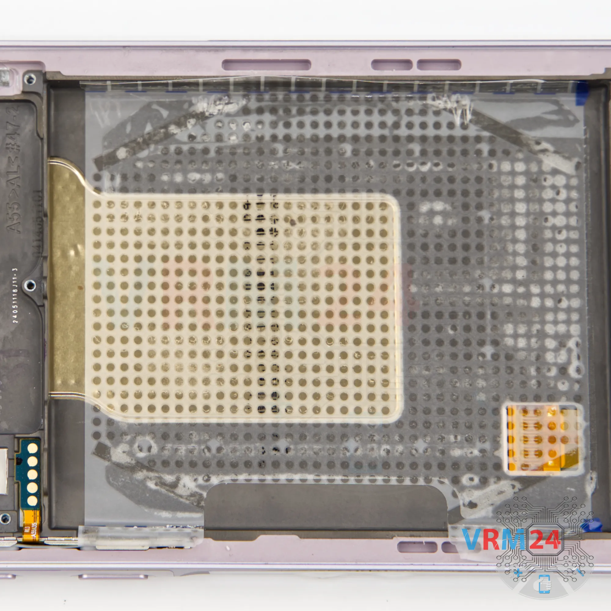
Step 16. Remove the motherboard
Now, carefully detach the motherboard. Lift it gently at the designated spots, remove it, and then flip it over.
⚠️️ Do not bend the circuit board when removing it or push tools under it. Unbeknownst to yourself, you can damage components or cables from the inside.


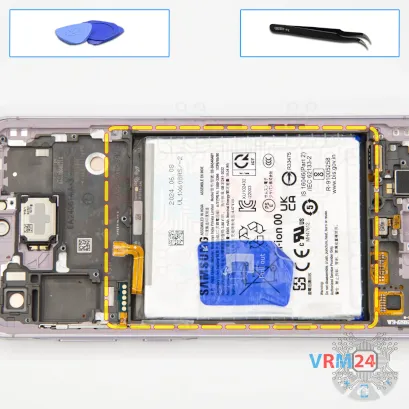
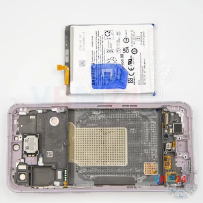


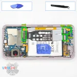
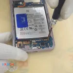
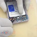
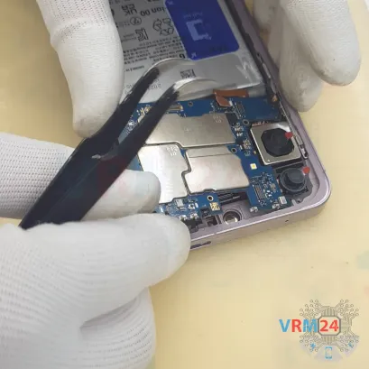
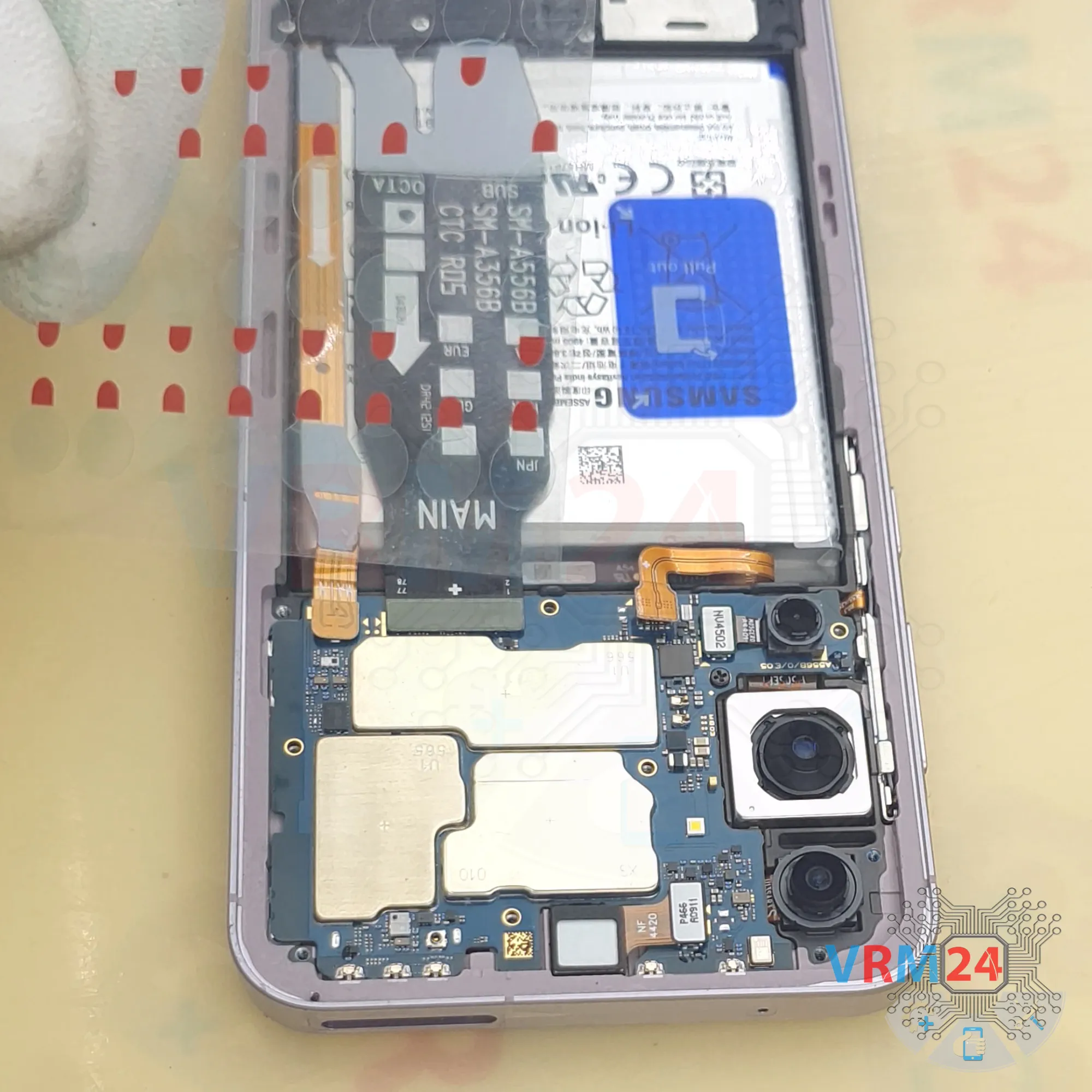
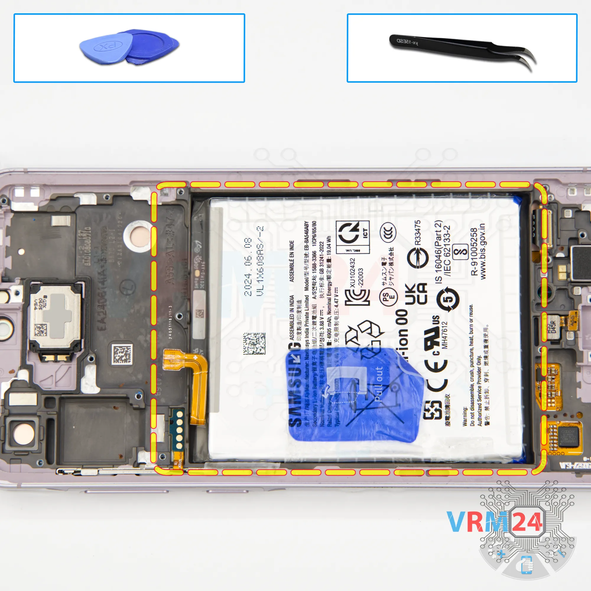
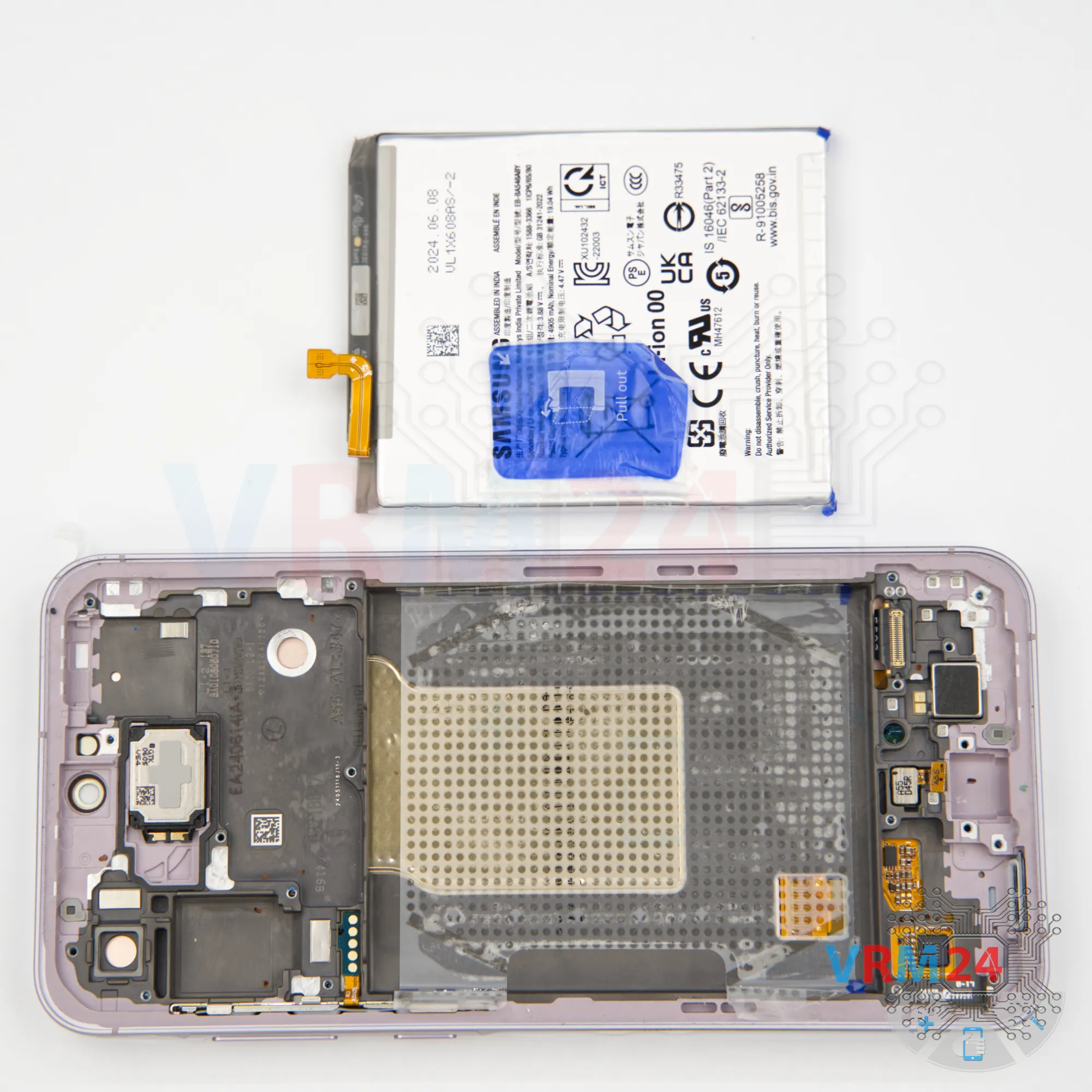
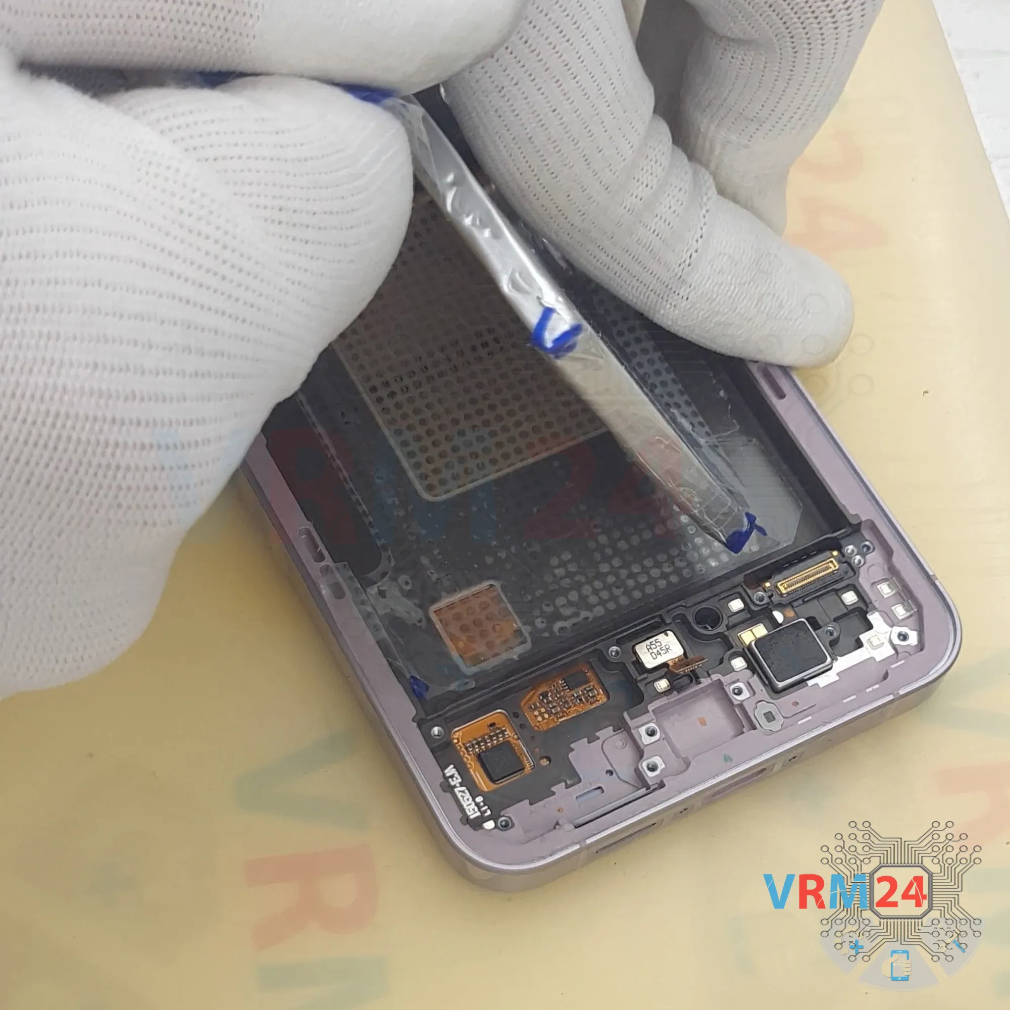
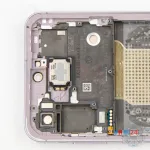
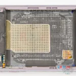
Step 18. Remove the battery
Finally, we move on to disconnecting the battery.
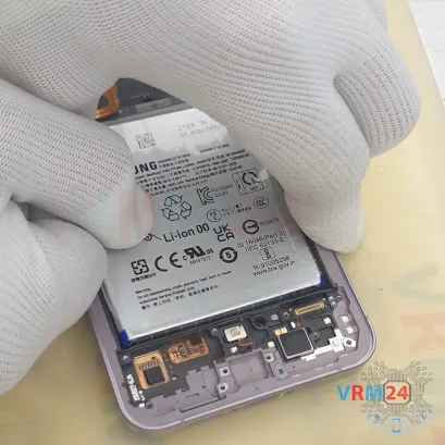
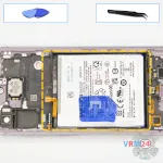
As is typical for this year’s series, there’s a blue tab that needs to be pulled up, and two transparent tabs on the edges that should be turned fully to the sides to keep them out of the way.
Carefully turn the edge tabs aside, then pull up the blue tab in the middle to disconnect the battery.

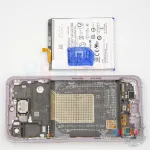
Step 19. In the display frame remained
ℹ️️ In the display frame remained: the earpiece speaker, vibration motor, side buttons.
Detailed disassembly instructions of Samsung Galaxy A55 SM-A556 in the video, made by our mobile repair & service center:
If you have a question, ask us, and we will try to answer in as much detail as possible. If this article was helpful for you, please rate it.

Disassembling\Repair has medium complexity and takes about minutes in time.
Our manual is suitable for all models Samsung Galaxy A55 SM-A556 — Samsung Galaxy A55 SM-A556V, SM-A556B, SM-A556B/DS, SM-A556E, SM-A556E/DS, SM-A5560 released for markets in different countries.
Back to the list