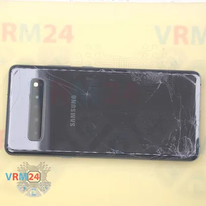
⚠️️ Before disassembling, do not forget to turn your phone off.
Moderate
Recommended tools


Disassembly/Repair of the mobile device Samsung Galaxy S10 5G SM-G977 (Samsung Galaxy S10 5G SM-G977B; SM-G977U; SM-G977N ; SM-G9770) with each step description and the required set of tools.

Vadim Popoff
Content manager / author / content specialist
Content specialist with over 10 years of experience in the technology industry.
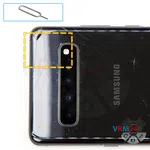
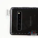
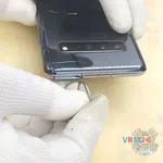
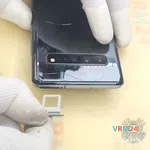
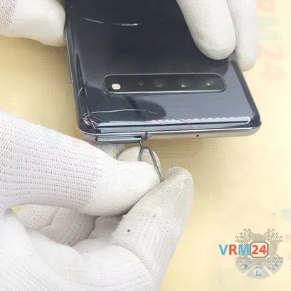
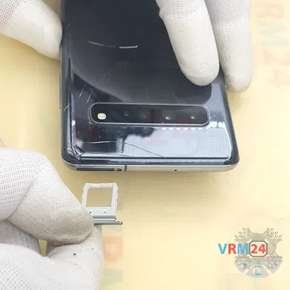
Step 2. Remove the tray
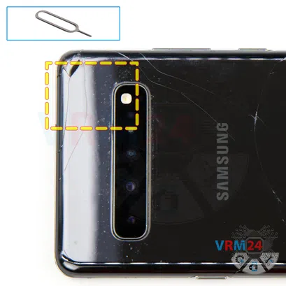
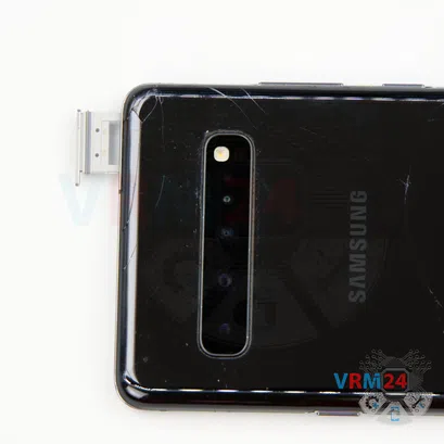
First of all, we need to remove the cards tray, and it is located in the upper part. For this we take a special tool, insert it into the hole and push out the tray for Sim cards.
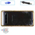
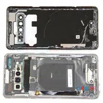
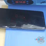
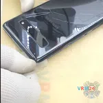
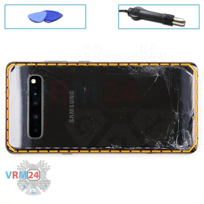
Step 3. Open the back cover
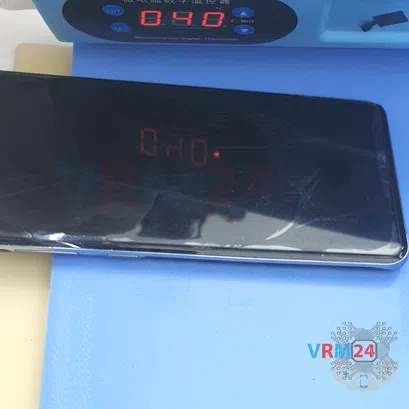
We need to heat the surface of the back cover to a temperature of about 65-70° C or 160° F. For this we use a heating mat you can use a hair dryer.
And after 5-7 minutes we can proceed to disassembly.
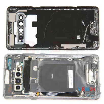
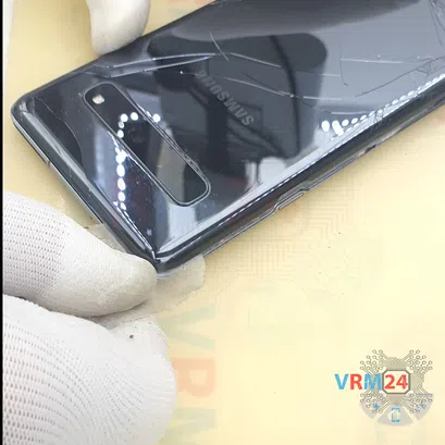
To remove the back cover, we will use a plastic film, this is the protective film from the new display. Insert it into the gap between the middle cover and the back cover and slide it along the back cover to detach it.
⚠️️ Always be careful around the side buttons, because there may be cables in this area and they can be damaged.
⚠️️ We also need to be careful around the cameras so as not to touch or damage the lenses.
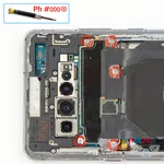
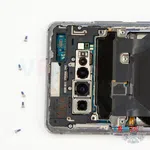
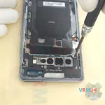
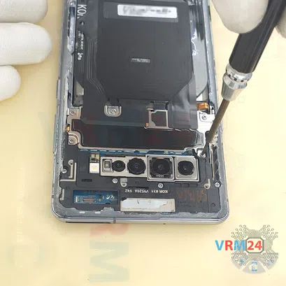
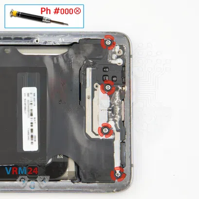
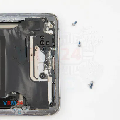
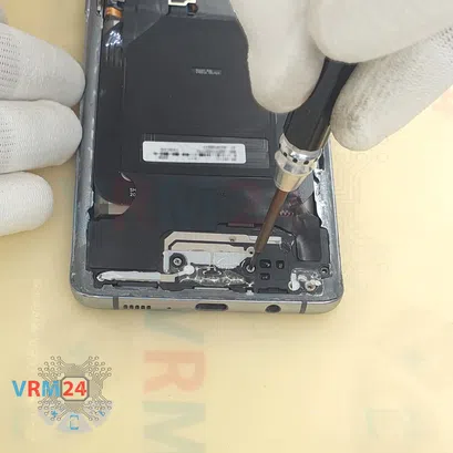
Step 4. Unscrew the screws
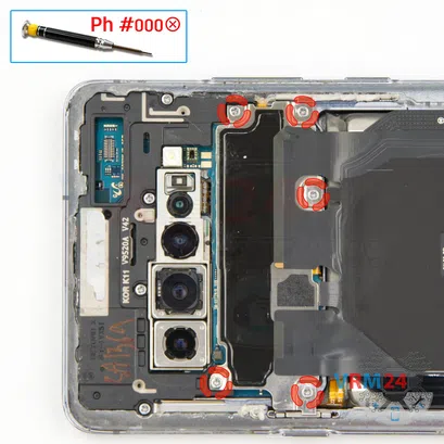
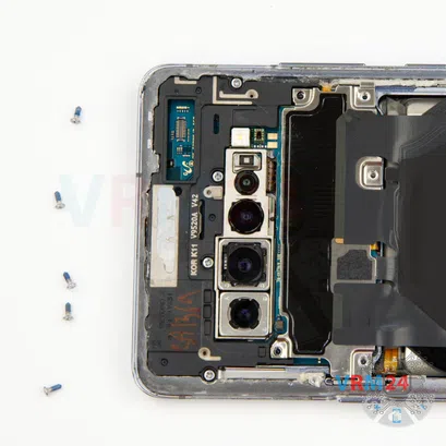
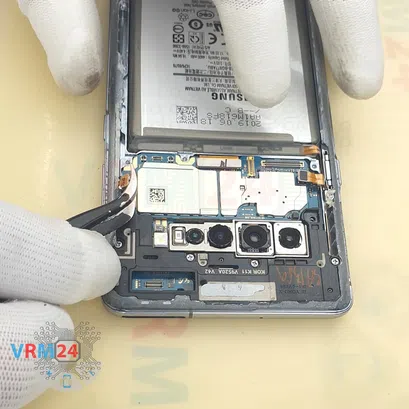
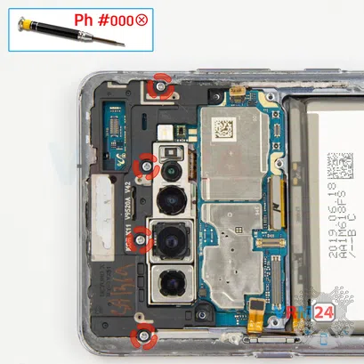
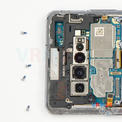
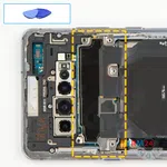
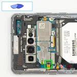
After this we need to unscrew the five screws at the top, for this we use a 1.5mm Phillips screwdriver or #000.
This will allow us to get to the battery connector which we will need to disconnect.

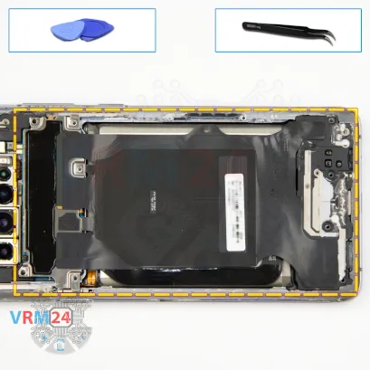
Step 5. Disconnect the connector
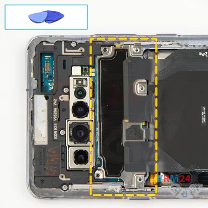
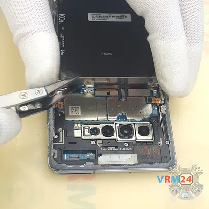
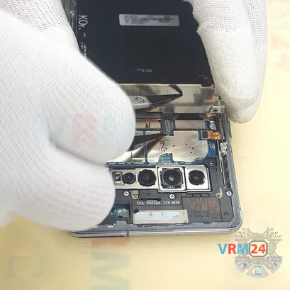
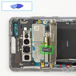
We need to carefully lift the cover and use a non-metal tool to disconnect the wireless charging connector.
Carefully disconnect the connector and bend the wireless charging to the side.
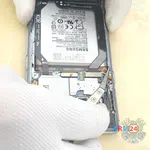
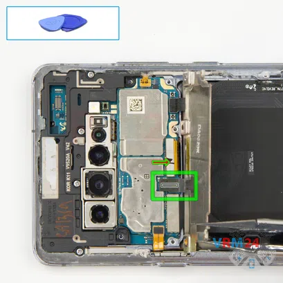
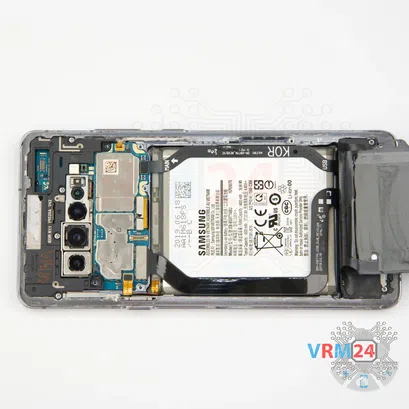
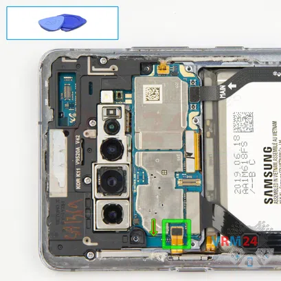
Step 6. Disconnect the battery connector
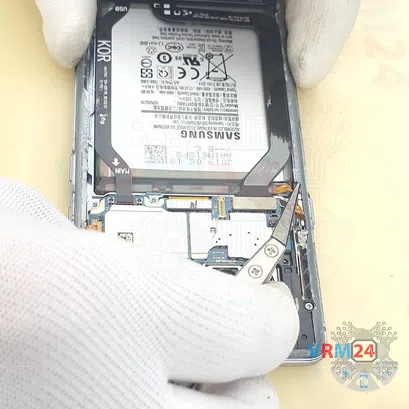
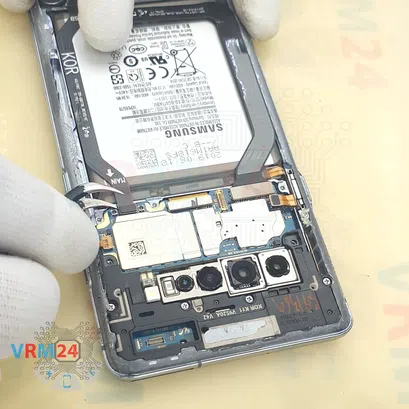
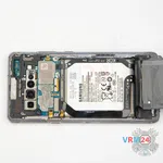
Using a non-metal tool we disconnect the battery connector.
The battery connector on our model is located in a slightly different place and therefore the cable runs along the side.
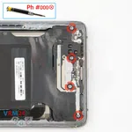
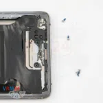
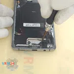
Step 7. Unscrew the screws
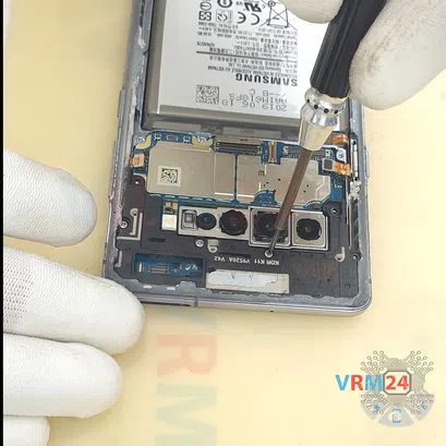
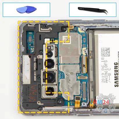
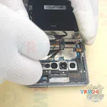
We move on to unscrewing the screws at the bottom. To unscrew the screws, we use the same screwdriver - 1.5 mm Phillips.
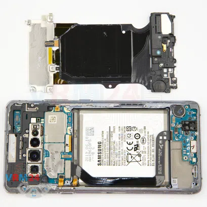
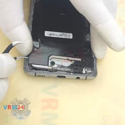
Step 8. Remove the loudspeaker
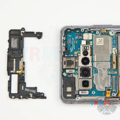
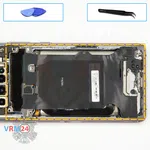
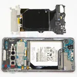
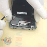
And we can detach the cover with the speaker. We find the right place for which we can hook the cover and lift it.
And we can remove the entire assembly.
Our assembly consists of wireless charging, NFC and speaker.
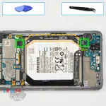
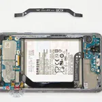
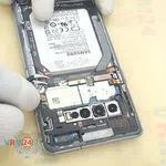
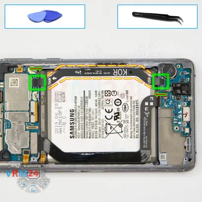
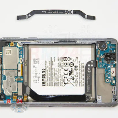
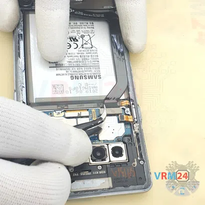
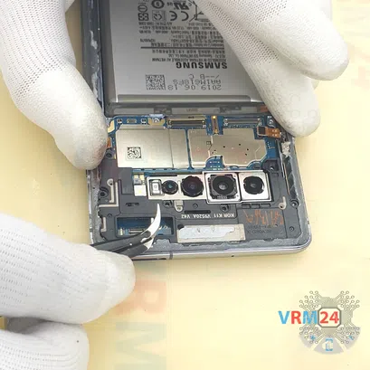
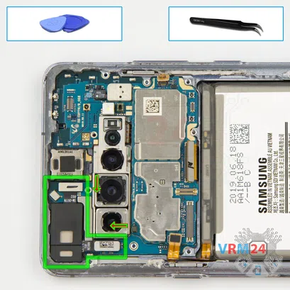
Step 9. Remove the interconnect cable
After this we can remove the inter-board cable. We hook up the connectors and remove the cable.
Please note that the arrows on the cable indicate the direction to the motherboard and the are some notices that also indicate the location in relation to the motherboard and sub-board.
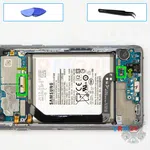
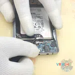
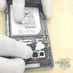
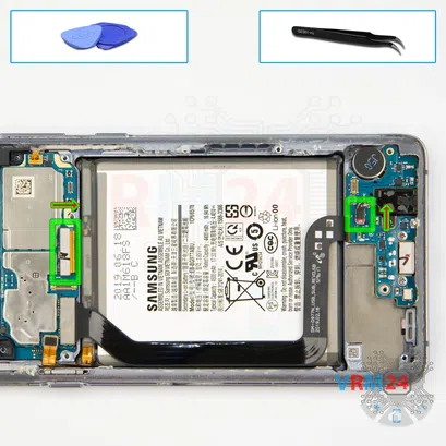
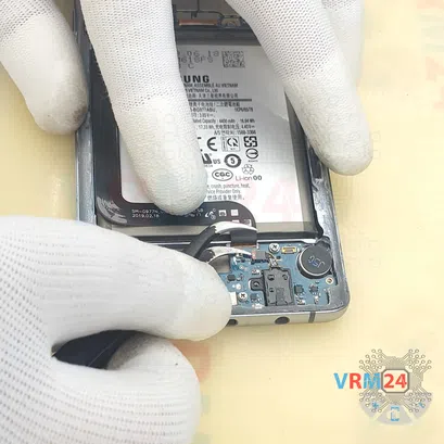
Step 10. Disconnect the connectors
Then we disconnect the connectors of the headphone jack port cable and inter-board cable.
⚠️️ We need to be careful because the cable of the headphone port is really thin and can be easily damaged.
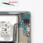
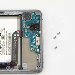
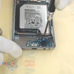
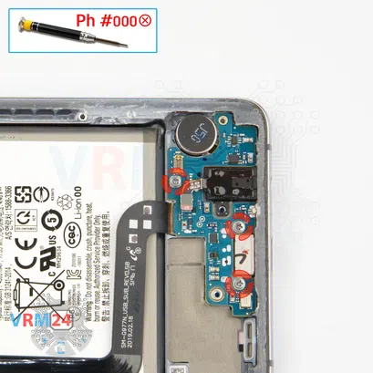
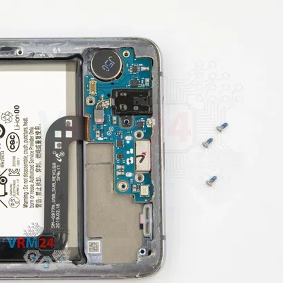
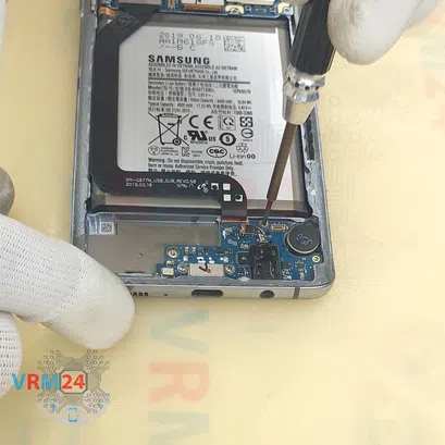
Step 11. Unscrew the screws
And we need to unscrew the three screws securing the sub-board.
The screwdriver is the same Phillips 1.5 mm.
The screws may be different, so we recommend placing them on a special surface in an easy-to-remember order so as not to mix anything up during reassembly.
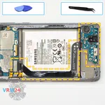
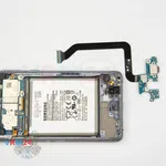
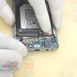
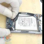
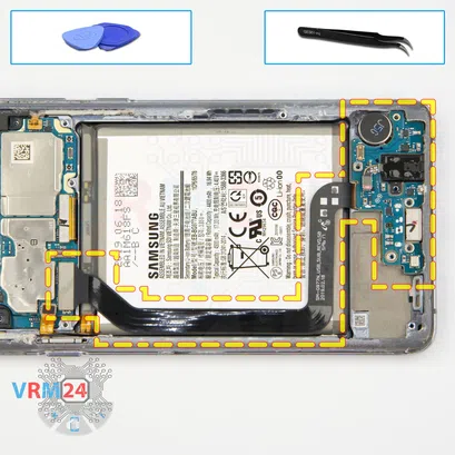
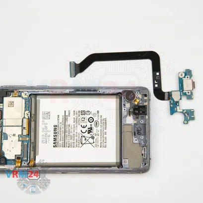
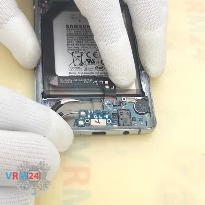
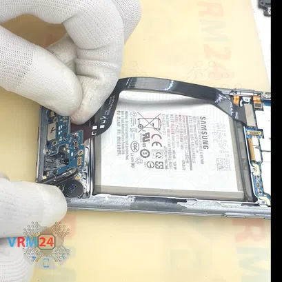
Step 12. Remove the sub-board
And we can detach the sub-board, carefully pick it up by the edge and try to lift the sub-board.
⚠️️ The sub-board is slightly recessed and the cable of the headphone jack port is thin and can be easily damaged, so be careful.
And we take out the sub-board with an inter-board cable.
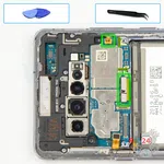
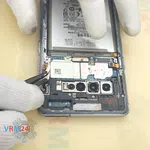
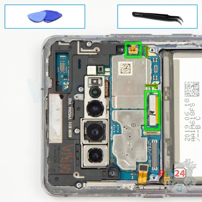
Step 13. Disconnect the connectors
Then we disconnect the side buttons cable connector and the connector of the cable to the display.
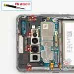
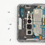
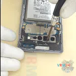
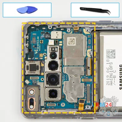
Step 14. Unscrew the screws
After we unscrew the remaining four screws fixing the cover and the motherboard. The screwdriver is the same 1.5 mm Phillips.
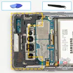
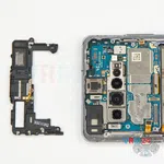
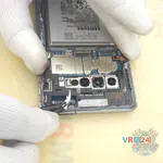
Step 15. Open the cover
Then carefully hook at the edge and detach the cover with antenna tracks. There is also a contact pad for the earpiece speaker on the cover.
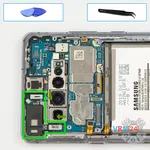
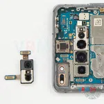
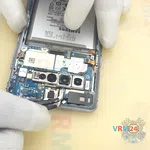
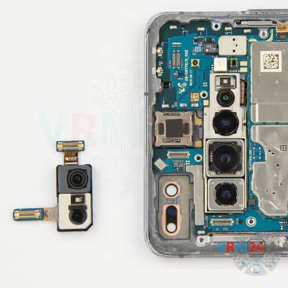
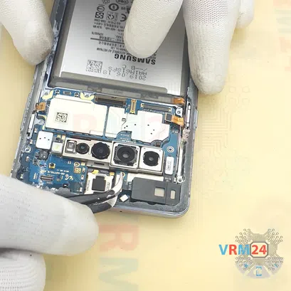
Step 16. Remove the front camera
Disconnect the two connectors and remove the front camera assembly.
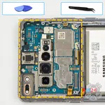
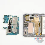
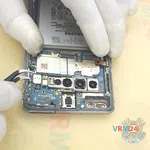
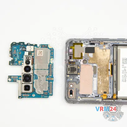
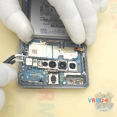
Step 17. Remove the motherboard
And we can detach the motherboard, find the right place to hook it.
Carefully, bend the cables so that they do not interfere with us and remove the motherboard.
As we can see there is an assembly of rear cameras attached to the back side.
⚠️️The assembly is firmly glued.
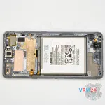
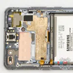
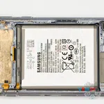
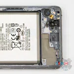
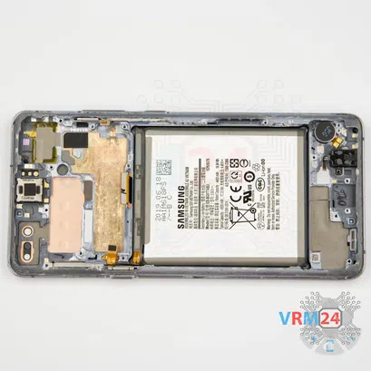
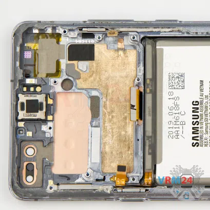
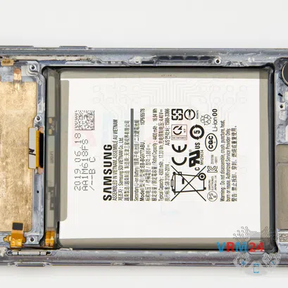
Step 18. In the display frame remained
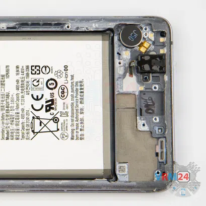
ℹ️️ In the display frame remained: the earpiece speaker, vibration motor, battery, and side buttons.
Detailed disassembly instructions of Samsung Galaxy S10 5G SM-G977 in the video, made by our mobile repair & service center:
If you have a question, ask us, and we will try to answer in as much detail as possible. If this article was helpful for you, please rate it.

Evgenii Kuzmin
Senior maintenance service and repair engineer
Back to the list

