

⚠️️ Before disassembling, do not forget to turn your phone off.
Teardown difficulty:
Moderate
Moderate
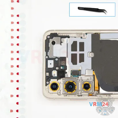
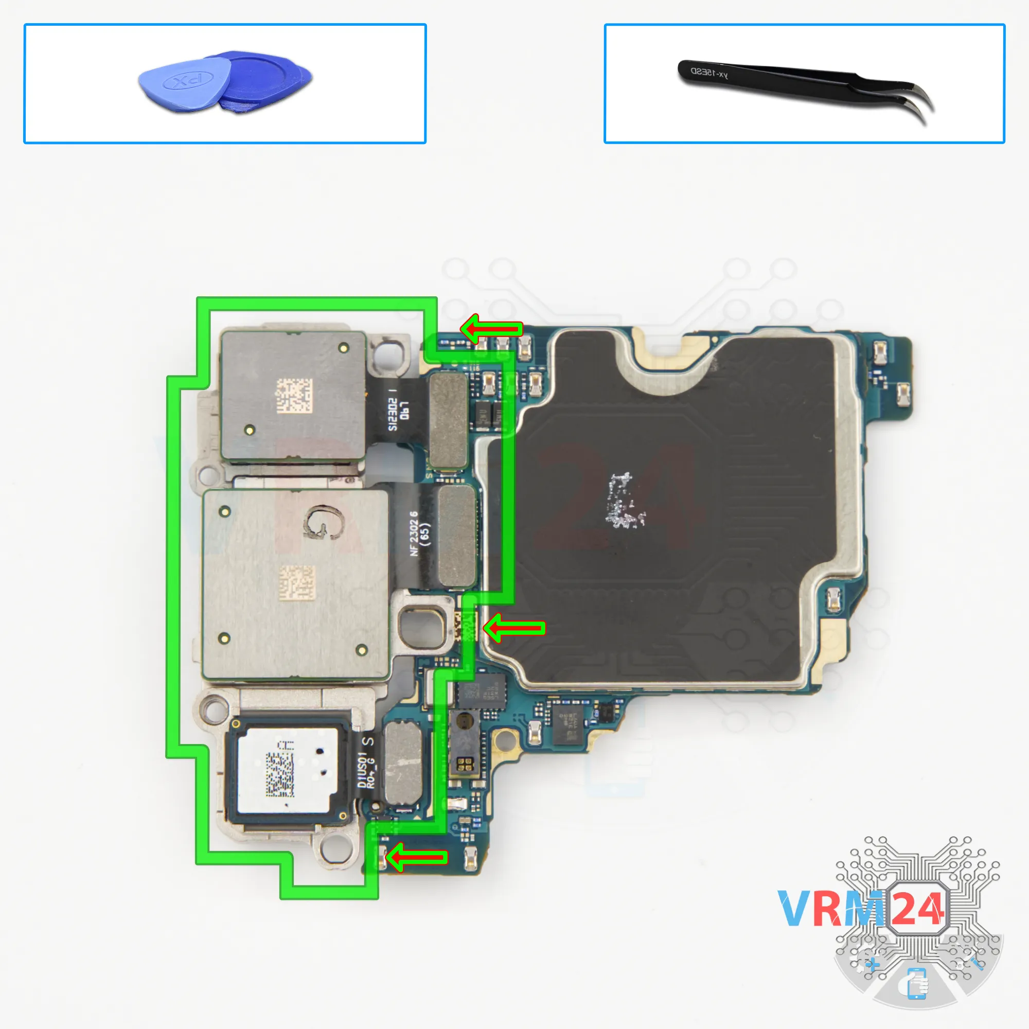
Recommended tools


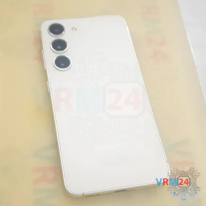
Disassembly/Repair of the mobile device Samsung Galaxy S23 SM-S911 (Samsung Galaxy S23 SM-S911B, SM-S911B/DS, SM-S911U, SM-S911U1, SM-S911W, SM-S911N, SM-S9110, SM-S911E, SM-S911E/DS) with each step description and the required set of tools.

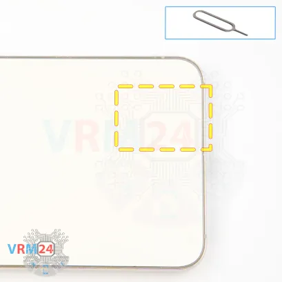
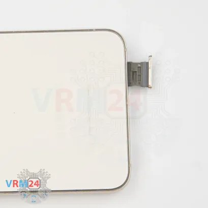
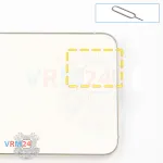
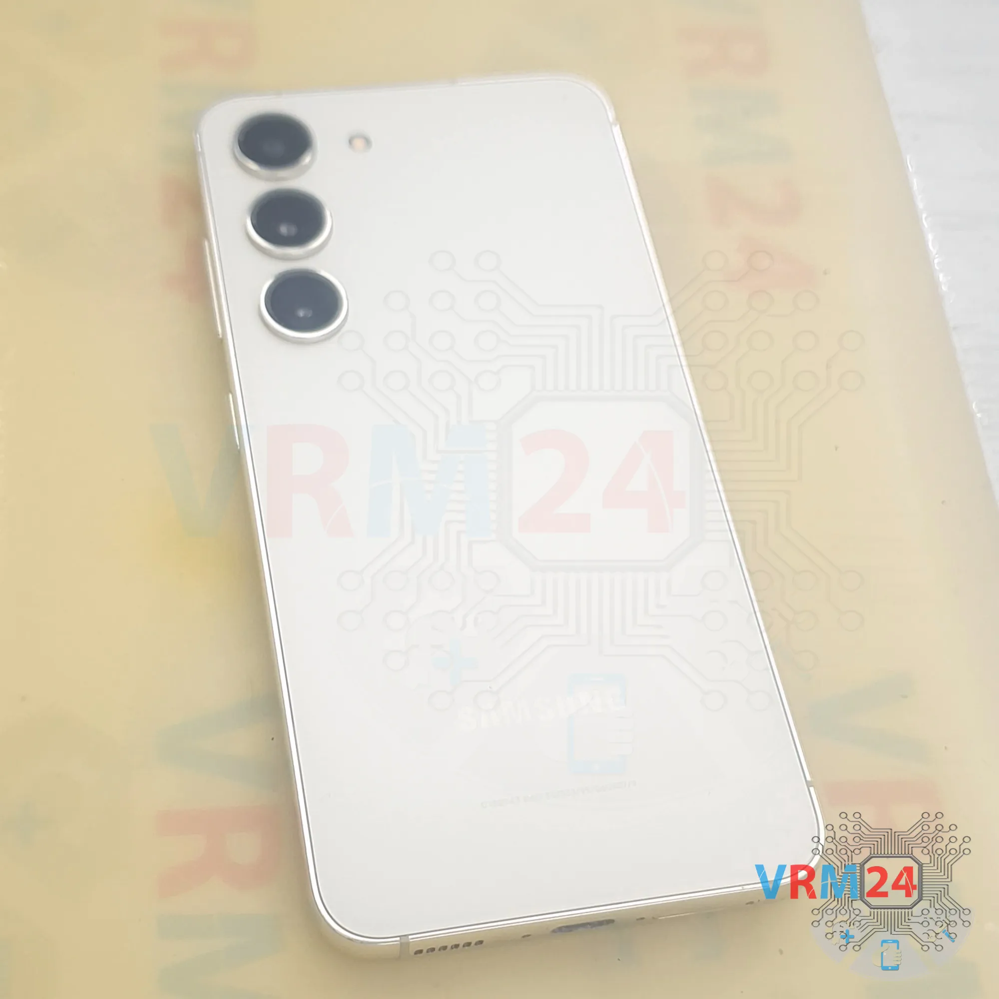
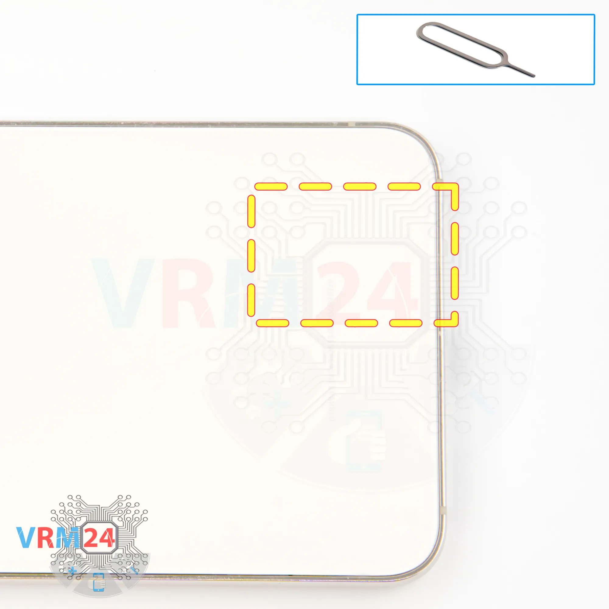
Step 2. Remove the tray
First, we need to remove the SIM card tray.
To do this, we use the SIM eject tool.
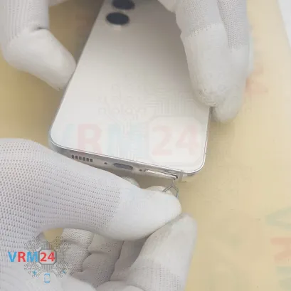
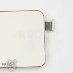
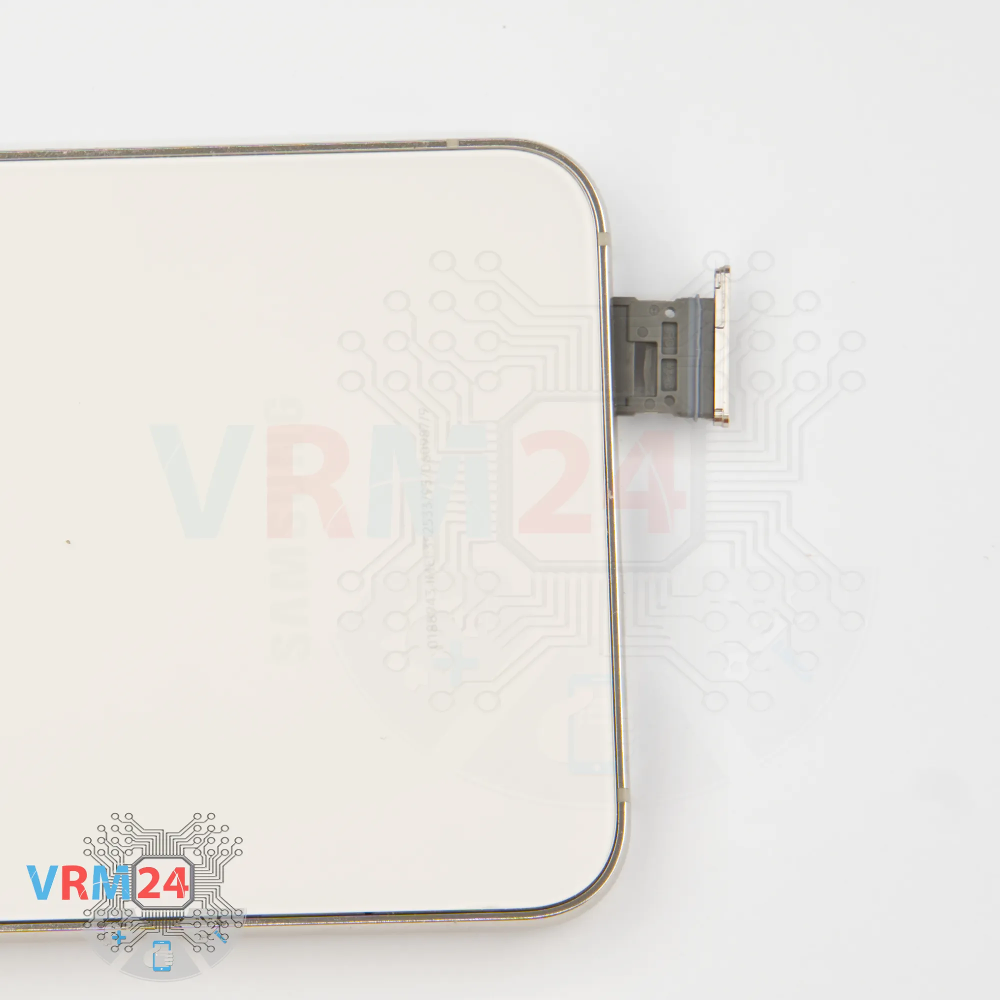
Insert it into the hole and carefully push out the tray.
If the tray doesn’t come out easily, we can also use tweezers to help.
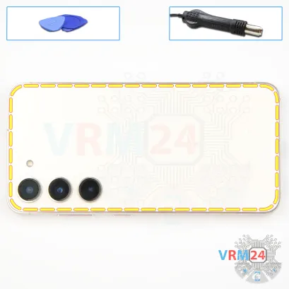
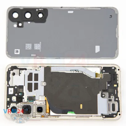
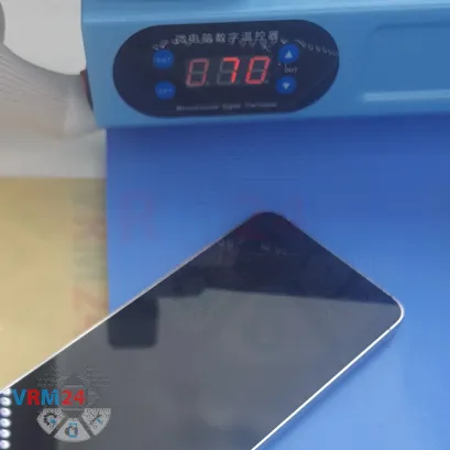

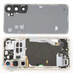


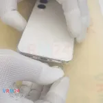
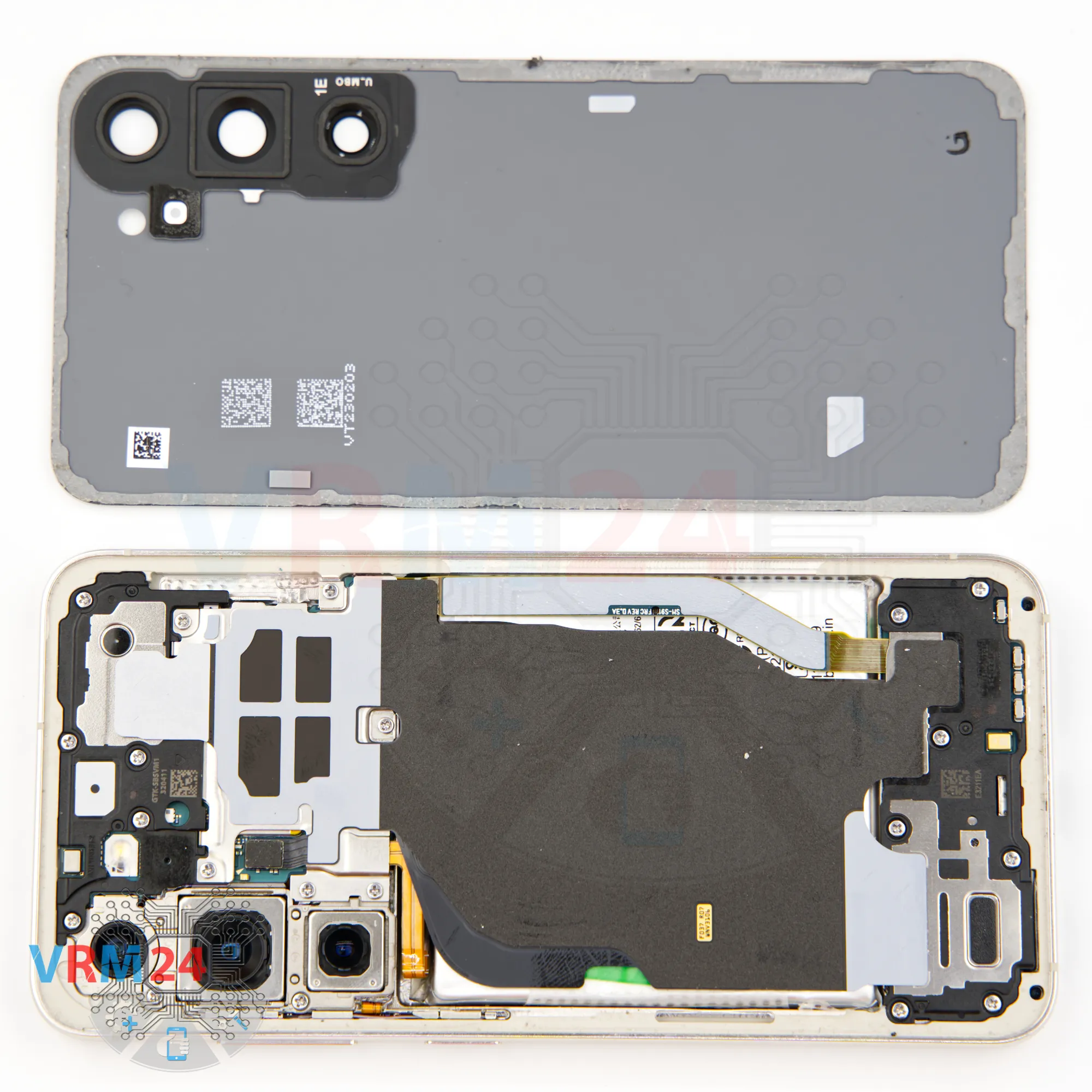
Step 3. Open the back cover
Next, we need to heat the back cover to around 70°C (160°F).
For this, we use a heating pad, but you can also use a hair dryer.
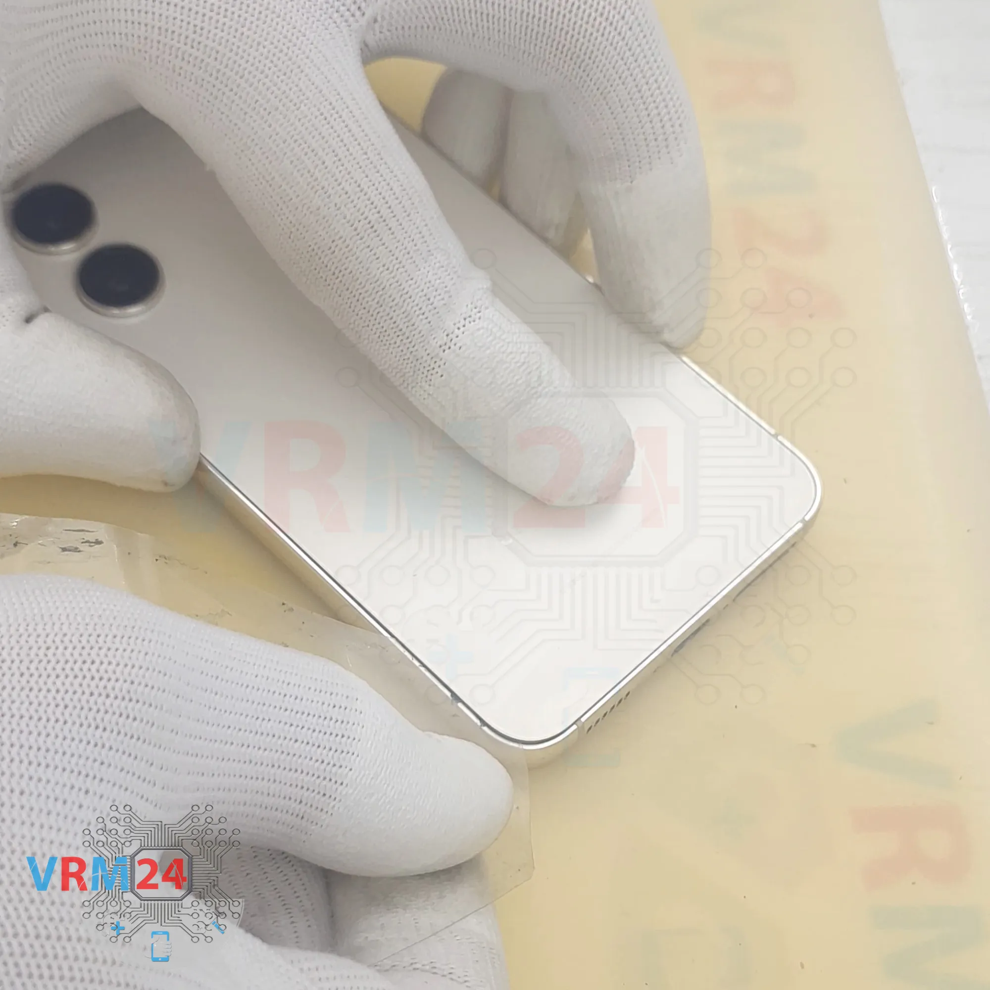
After 5–10 minutes, we move on to removing the back cover. We use a thin plastic film for this. It can be the protective film from a new display or just a thin film of plastic from an office supply store. Carefully insert it into the gap between the back cover and the midframe, and slide it along the edge to cut through the adhesive layer.
As always, be extra careful around the cameras so you don’t accidentally scratch or damage the lenses. Also, take care around the buttons.


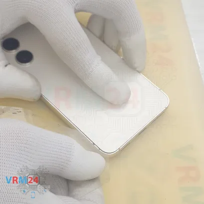
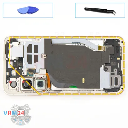
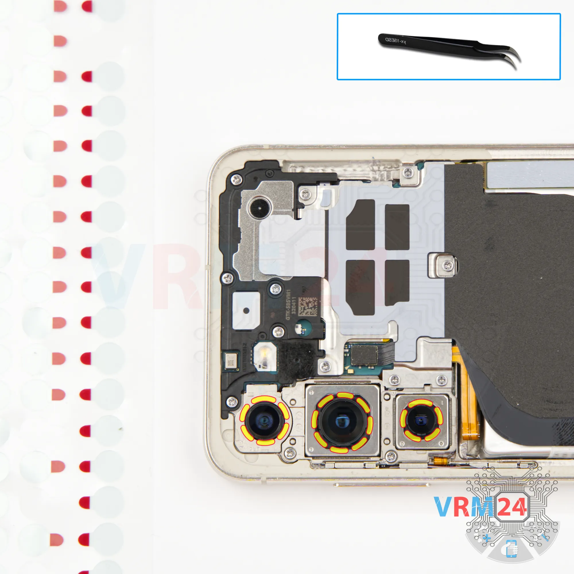
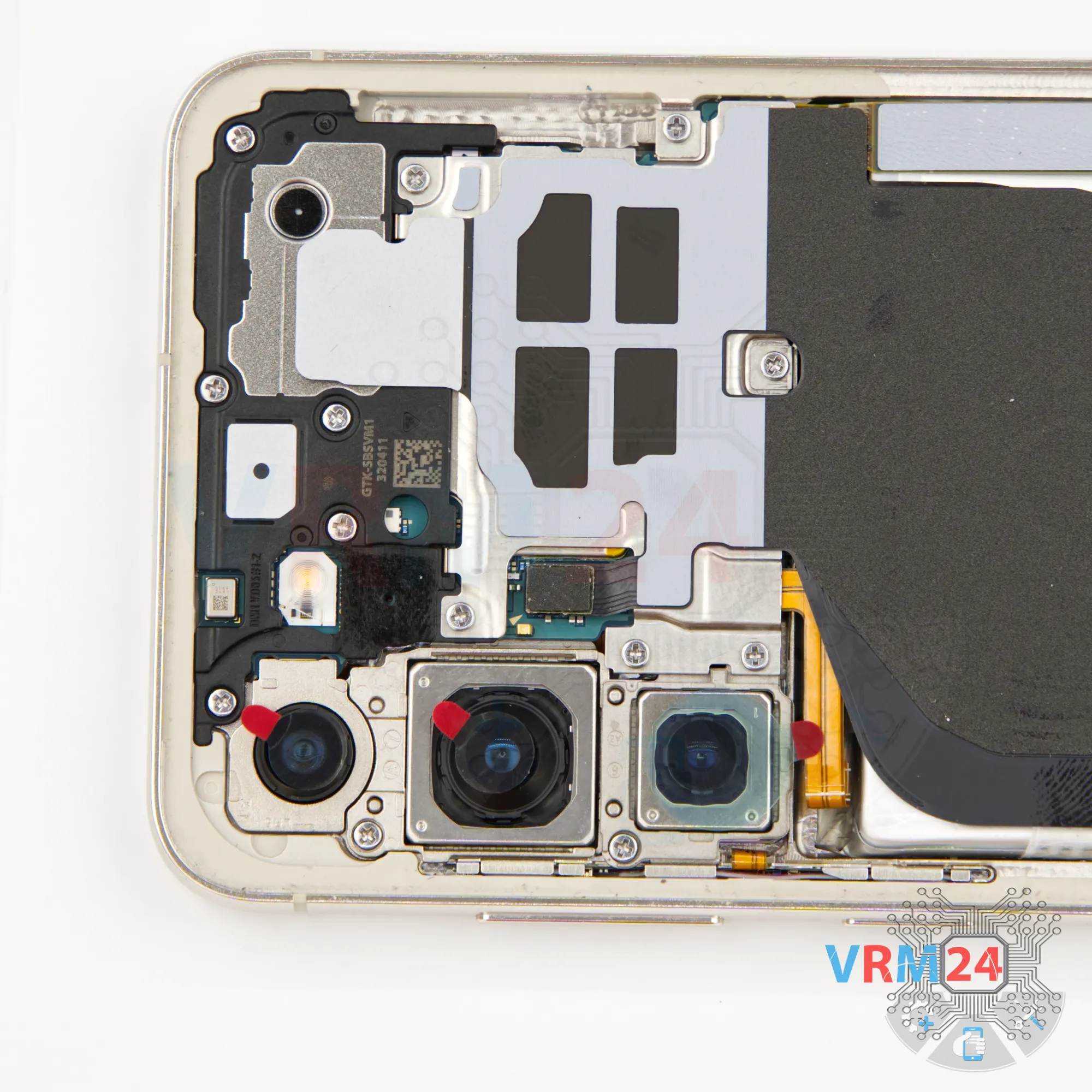
Step 4. Protecting camera lenses
We have to cover the camera lenses so dust doesn’t get in.
Notice that we stick the protective film not directly on the lenses, but on the rim around them.
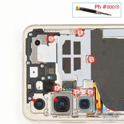
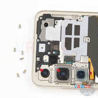


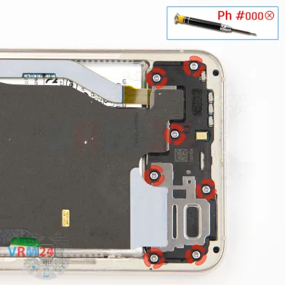
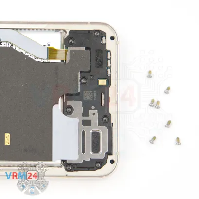
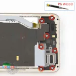
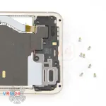
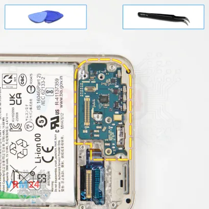
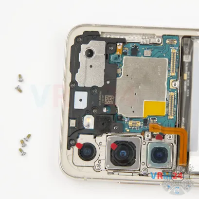
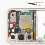
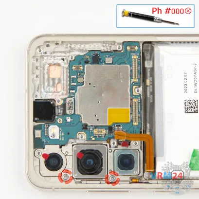
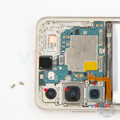
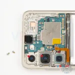
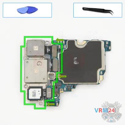
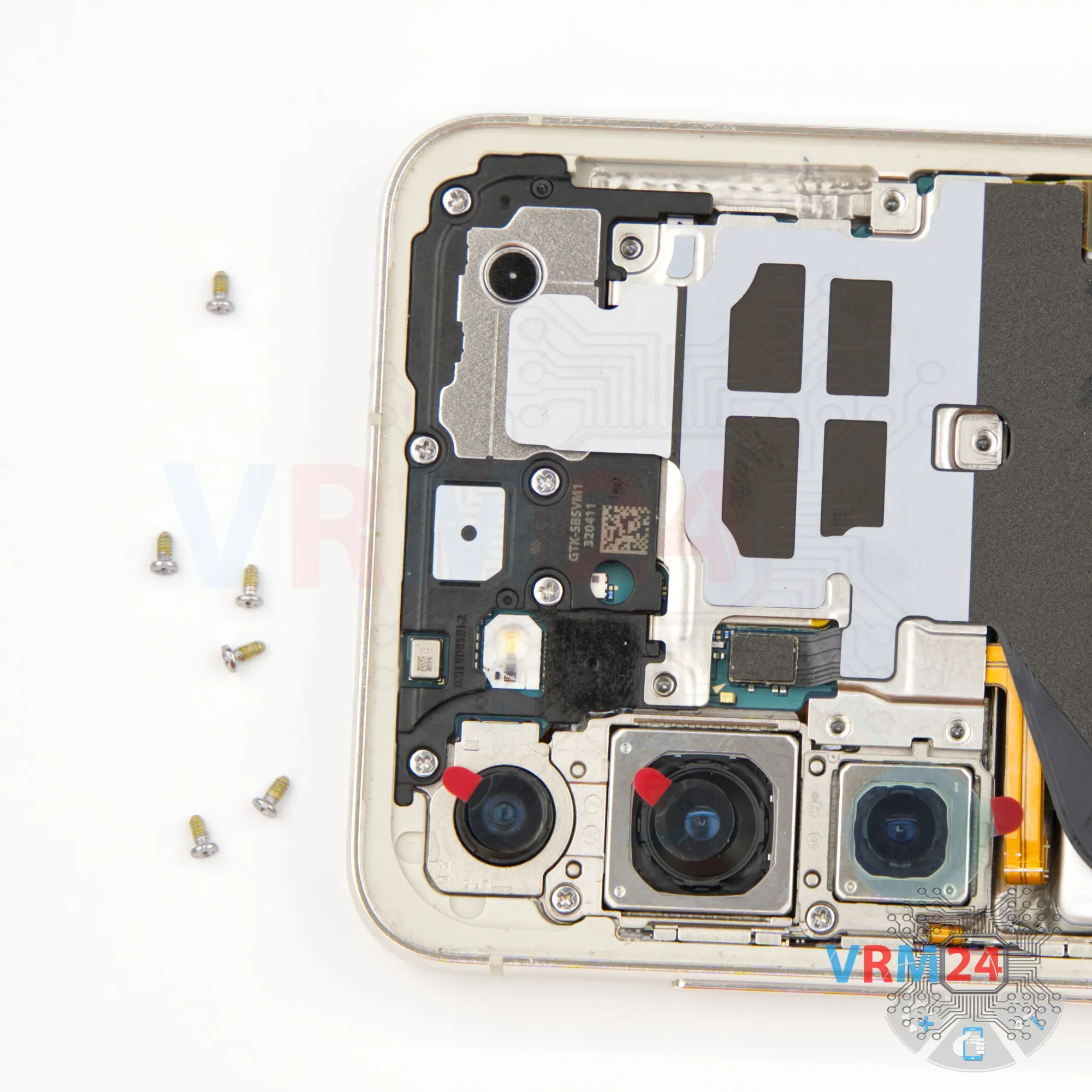
Step 5. Unscrew the screws
Next, we start removing screws. For this, we use a 1.5 mm Phillips screwdriver, also known as a Phillips #000.
We unscrew the screws holding the NFC and wireless charging assembly.


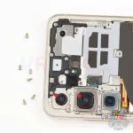
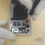
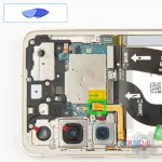
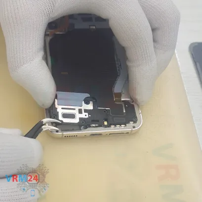
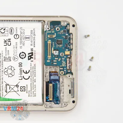
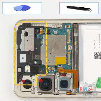
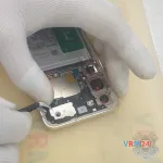
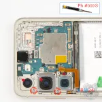
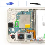
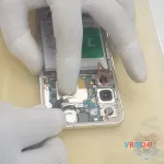
Step 6. Open the cover
We disconnect the connector. Then we carefully lift the assembly with a non-metal tool.


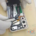
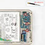
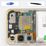
Step 7. Disconnect the battery connector
Disconnect the battery connector as soon as you can. Use a non-metallic or plastic tool to avoid any damage.
ℹ️️ The Samsung Galaxy S23 SM-S911 model has a battery EB-BS912ABY with a capacity of 3900 mAh (also known as a rechargeable battery).


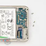
Step 8. Unscrew the screws
Now we move on to the screws at the bottom.
It’s best to fold the battery flex cable aside so the connector doesn’t accidentally snap back into place.
We remove the bottom screws using the same 1.5 mm Phillips #000 screwdriver.
It’s a good idea to keep these screws separate from the previous ones, just in case.

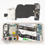

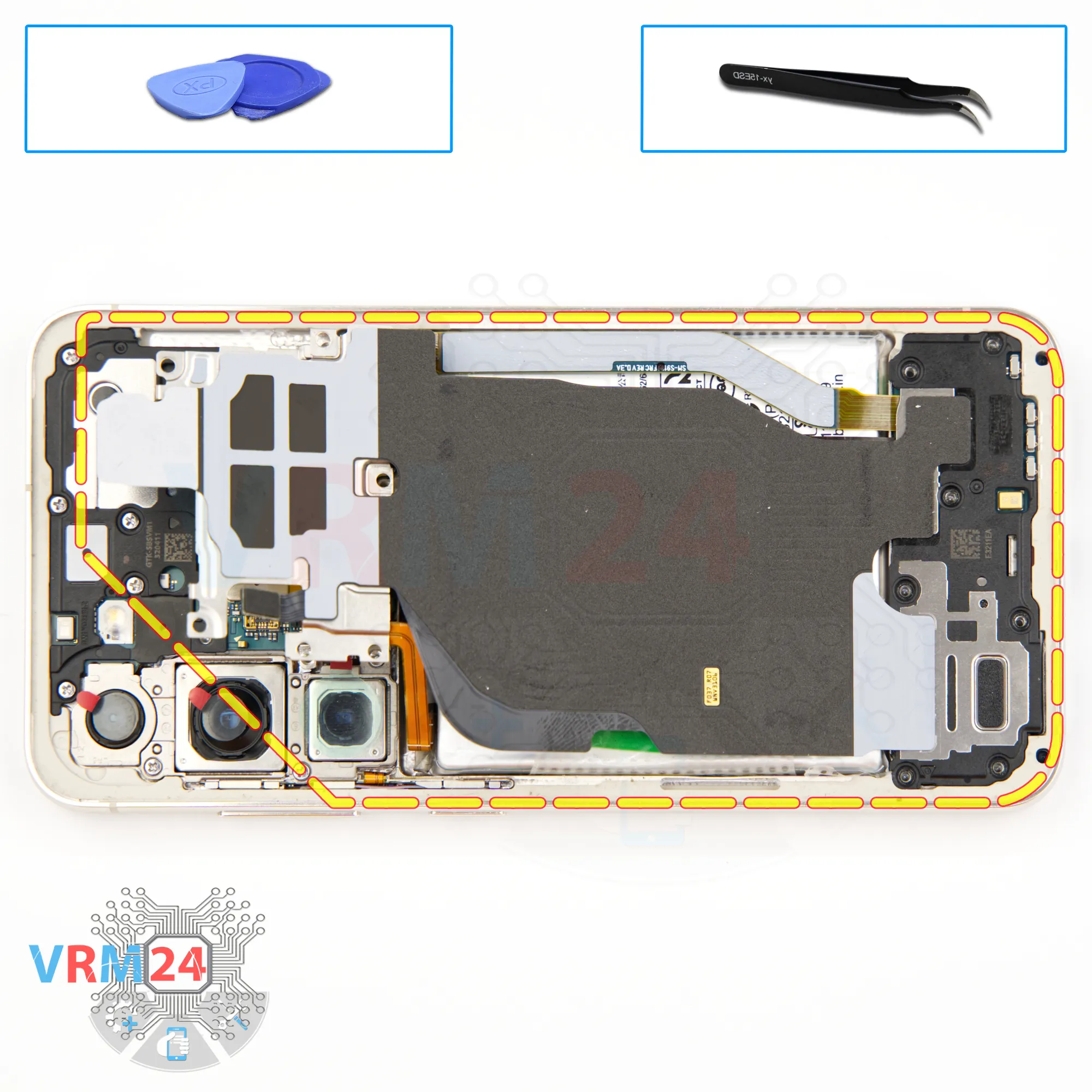
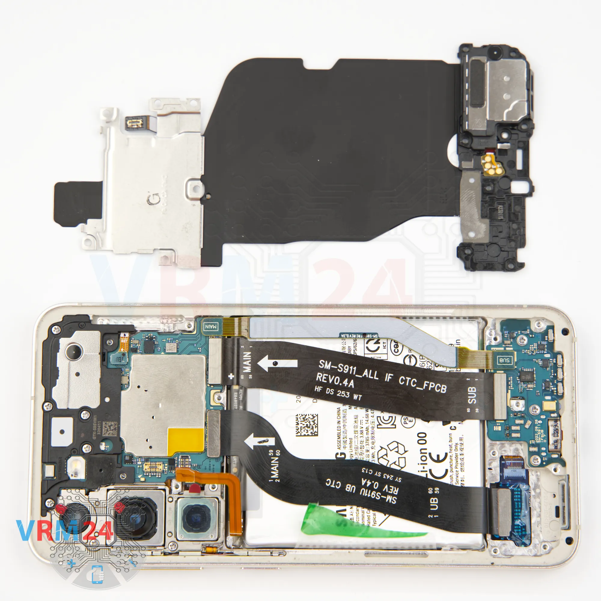
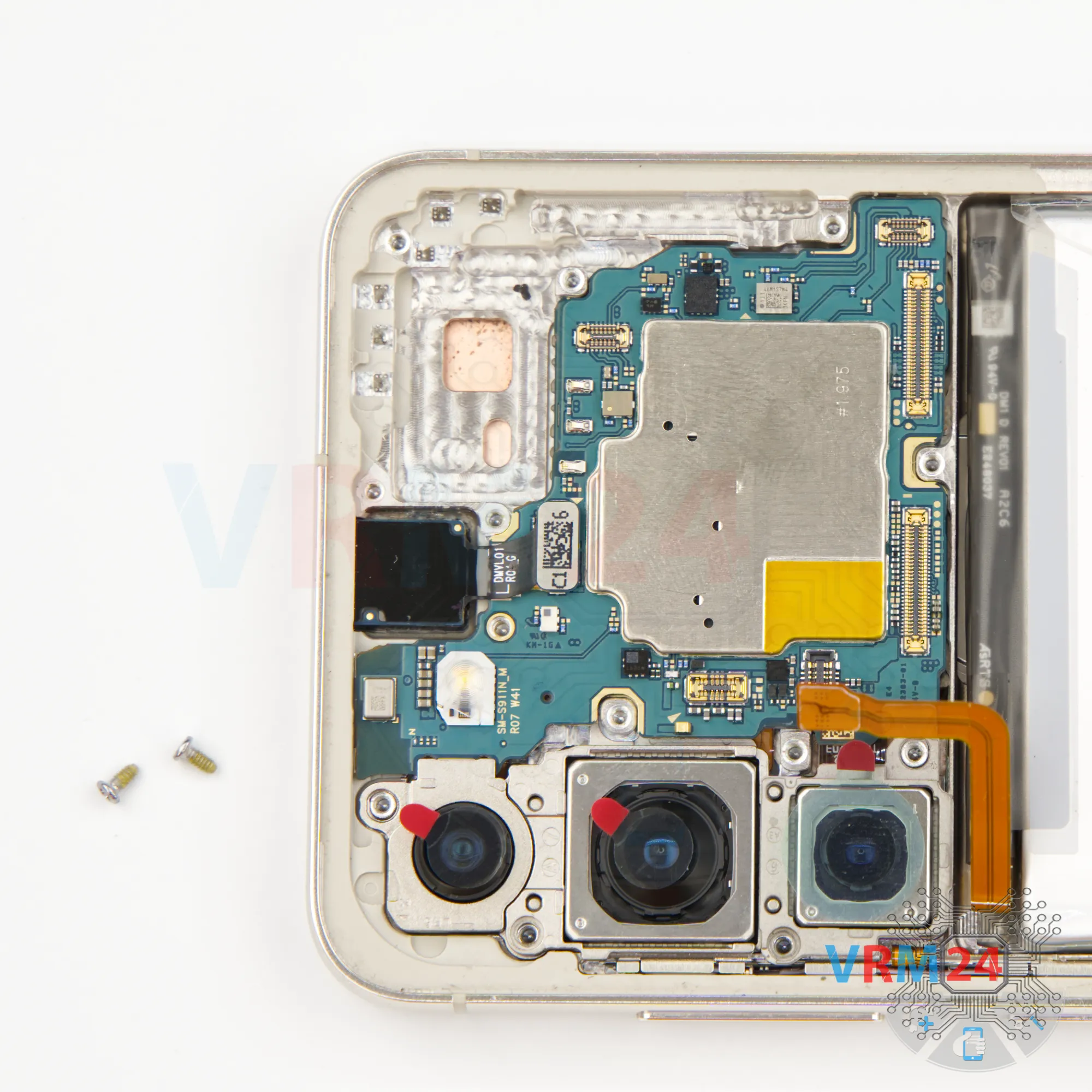
Step 9. Remove the loudspeaker
Next, we need to remove the loudspeaker cover.
Pry it up from the right spot, lift it, and set aside the cover along with the NFC and wireless charging module.
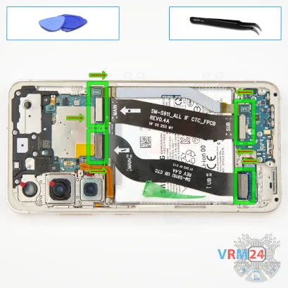
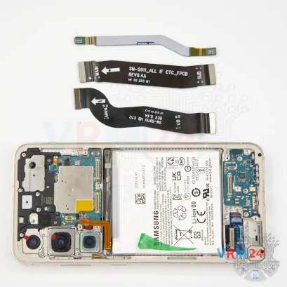

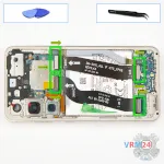
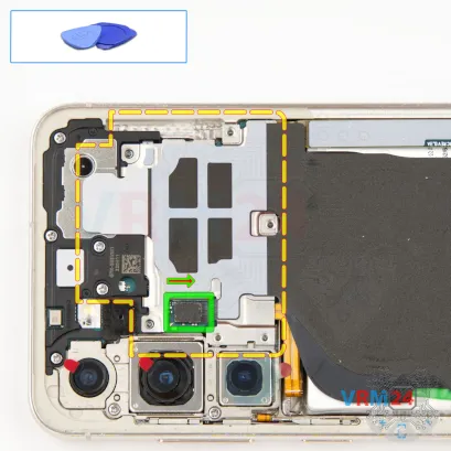
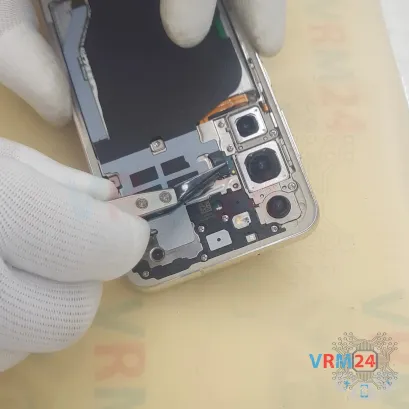
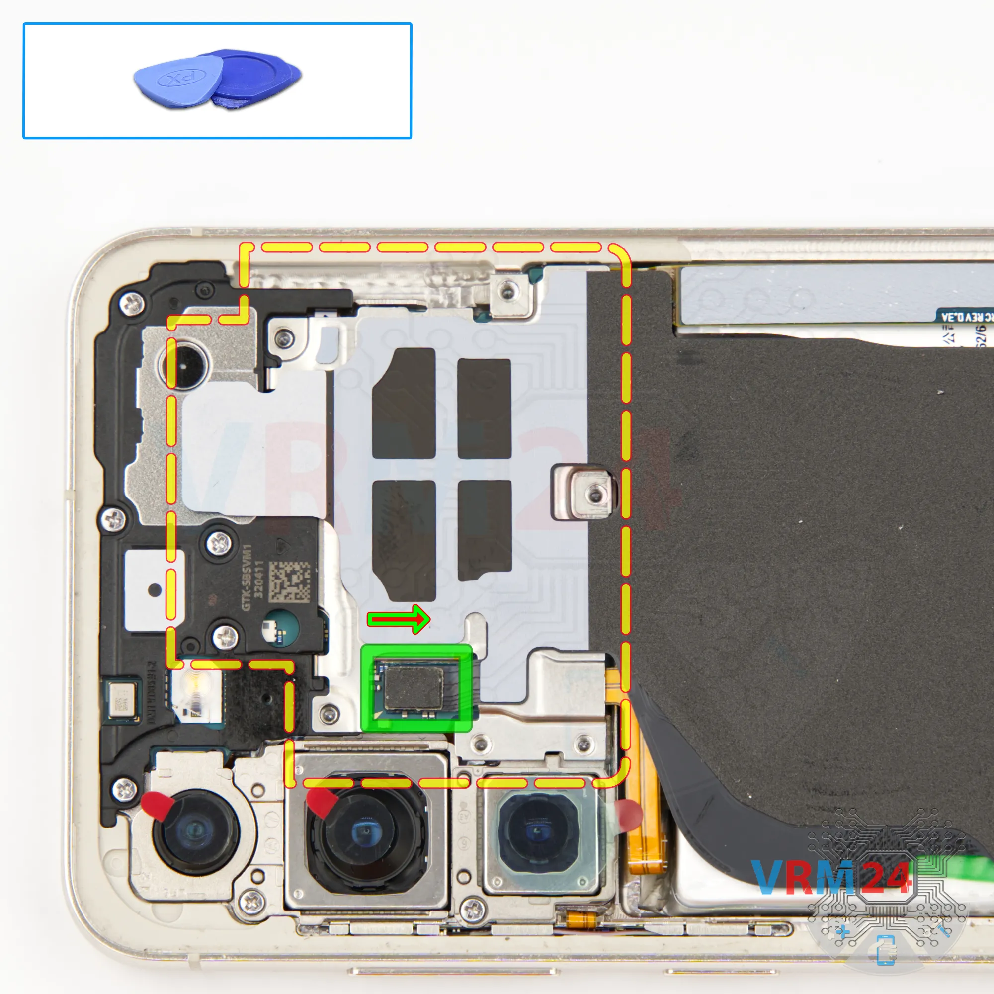
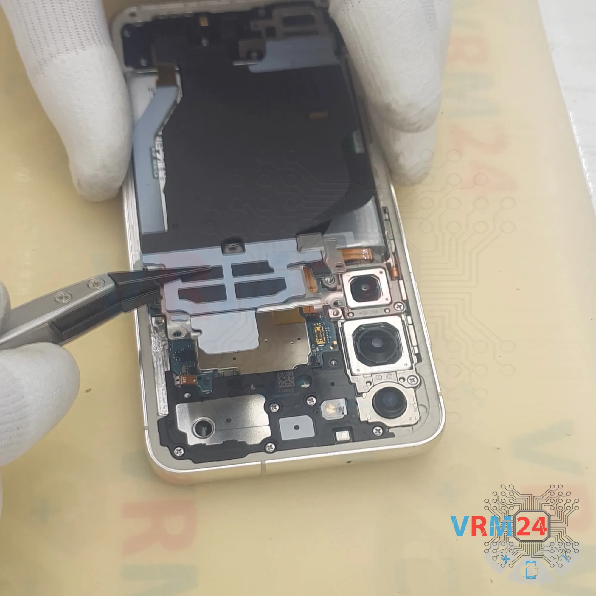
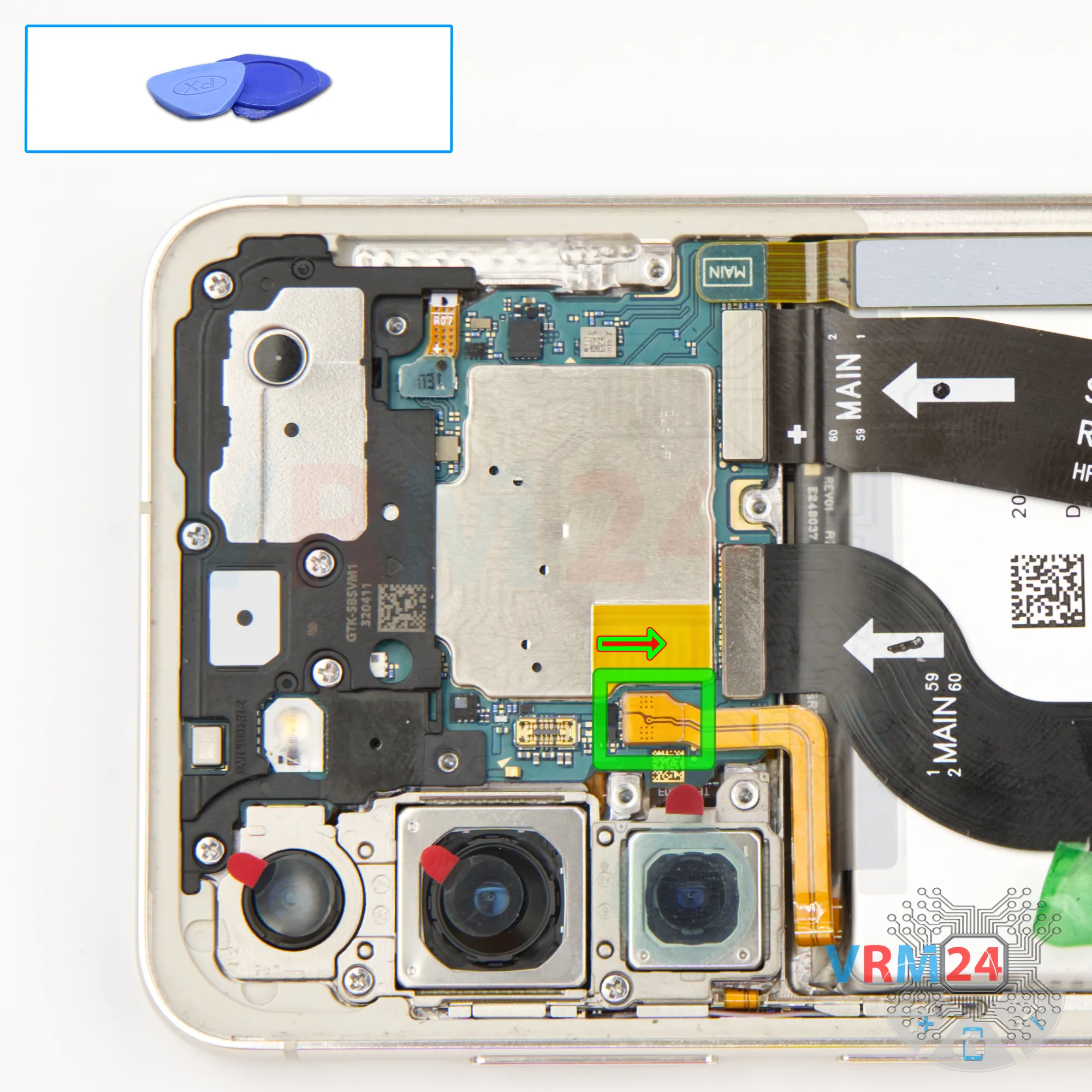
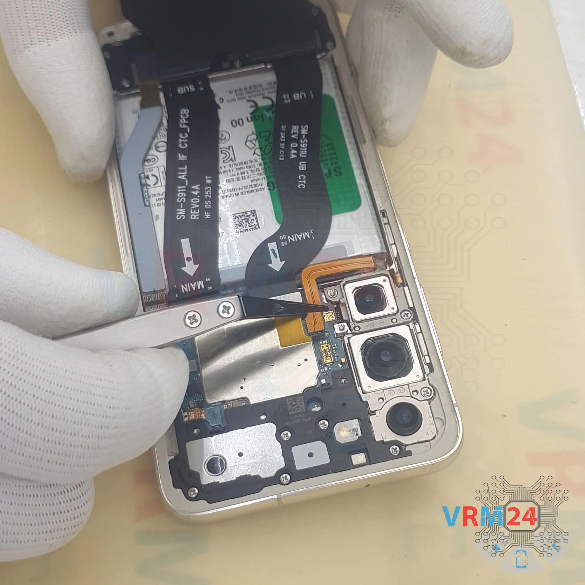
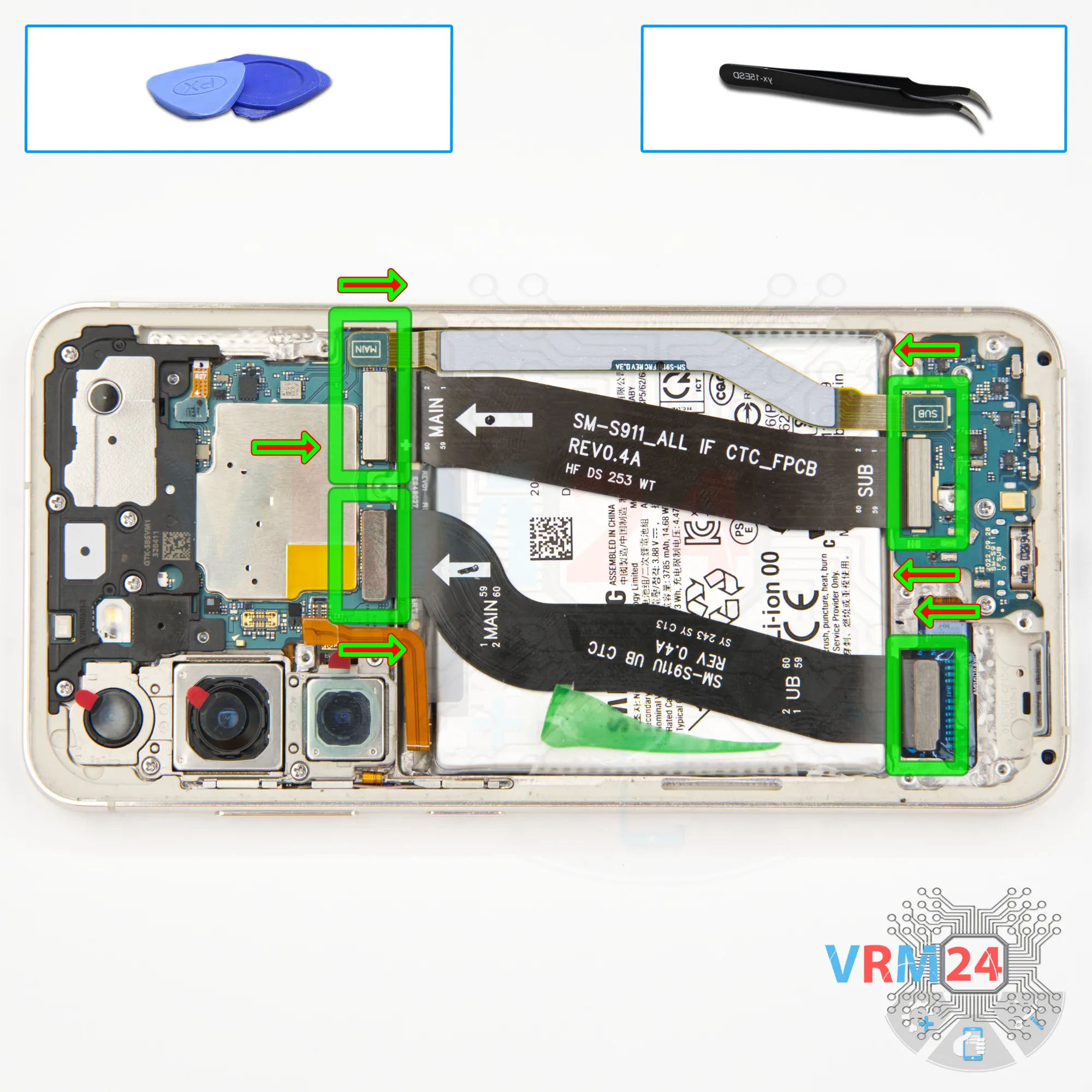
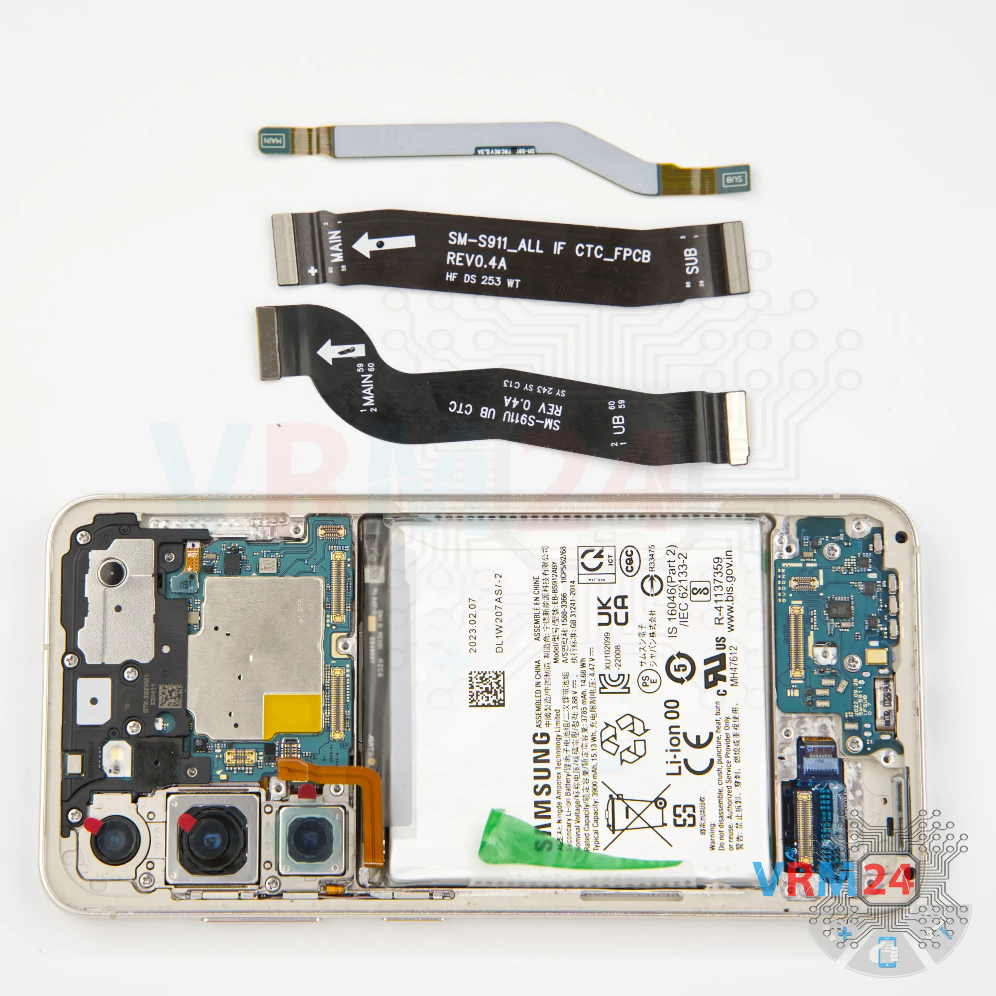
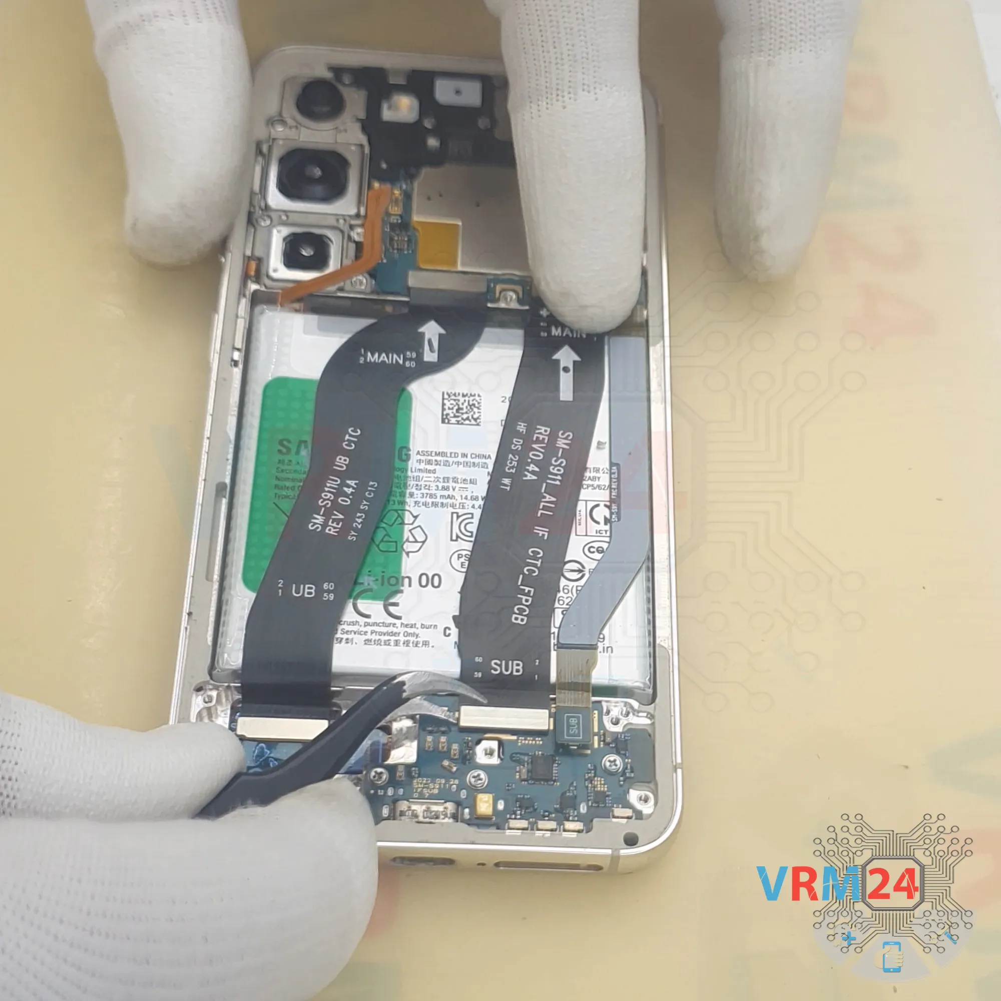
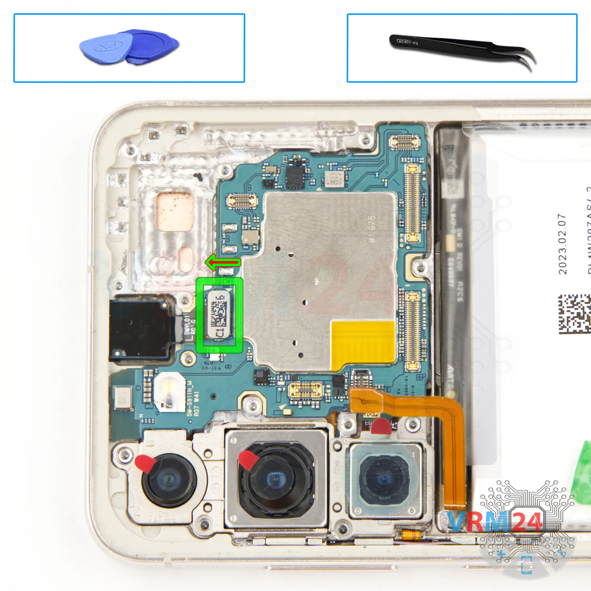
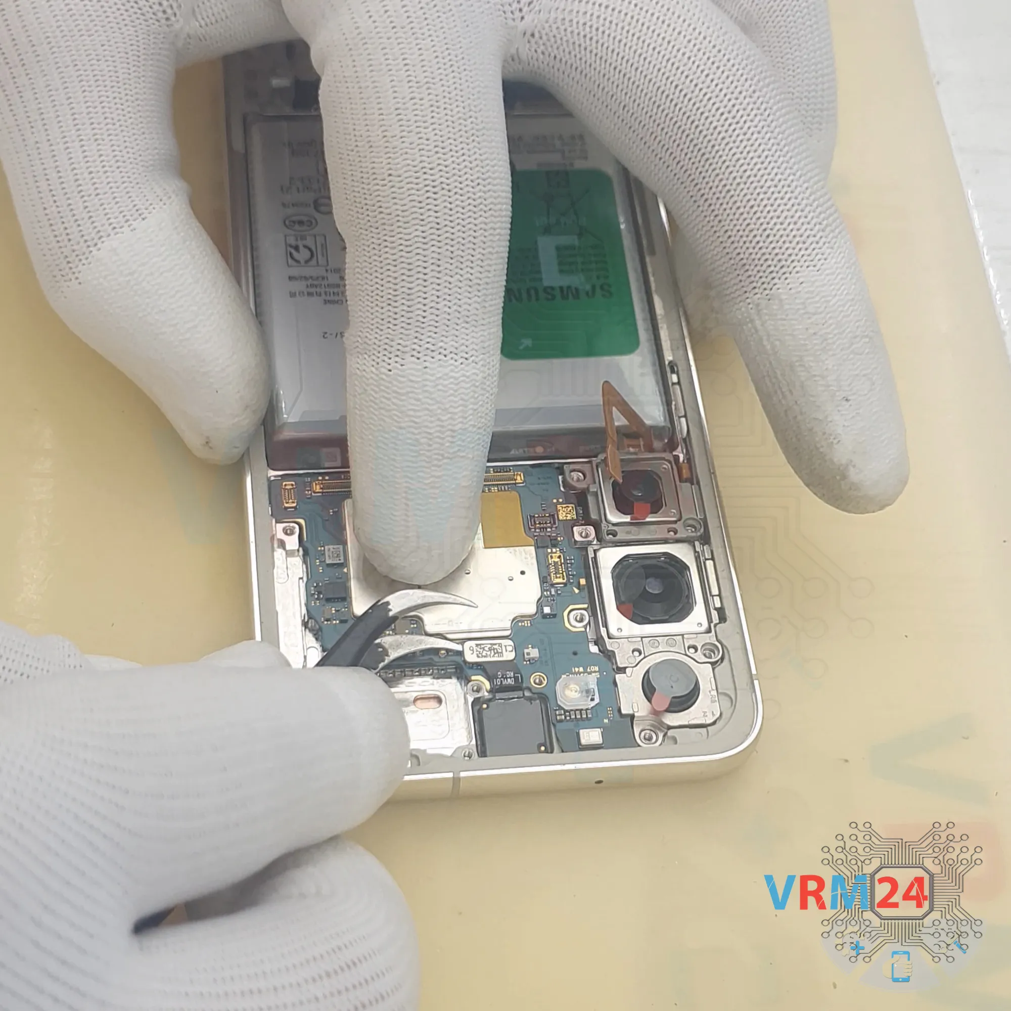
Step 10. Remove the interconnect cables
After that, we disconnect the interconnect flex cables and the antenna cable and move them aside.
By the way, the flex cables have arrows showing the direction toward the motherboard.
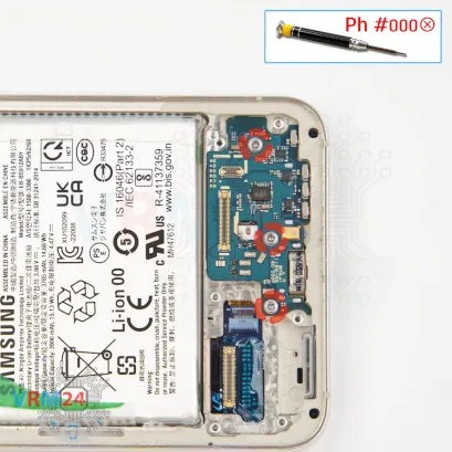


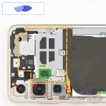
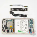
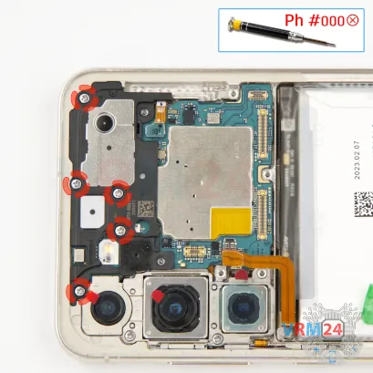
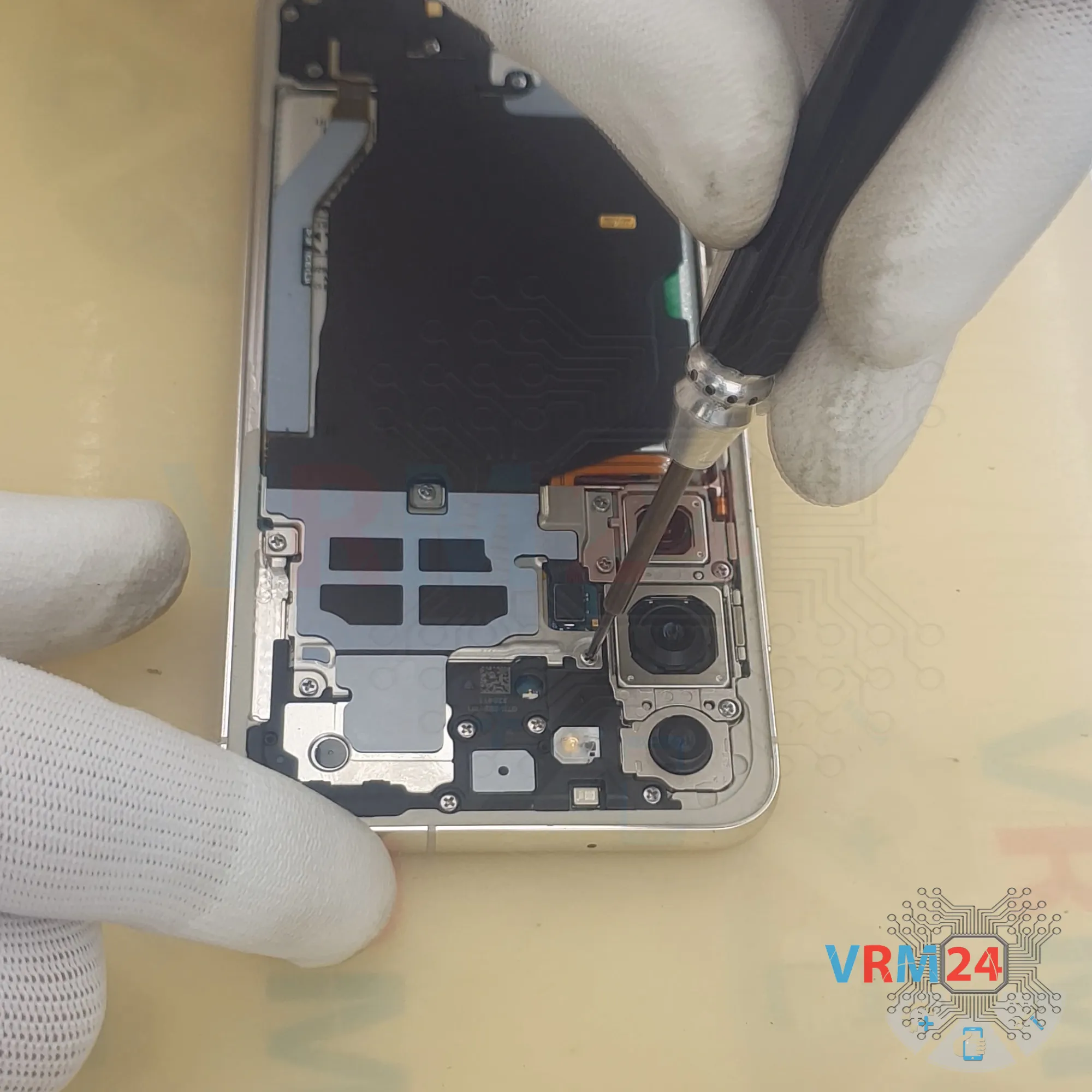
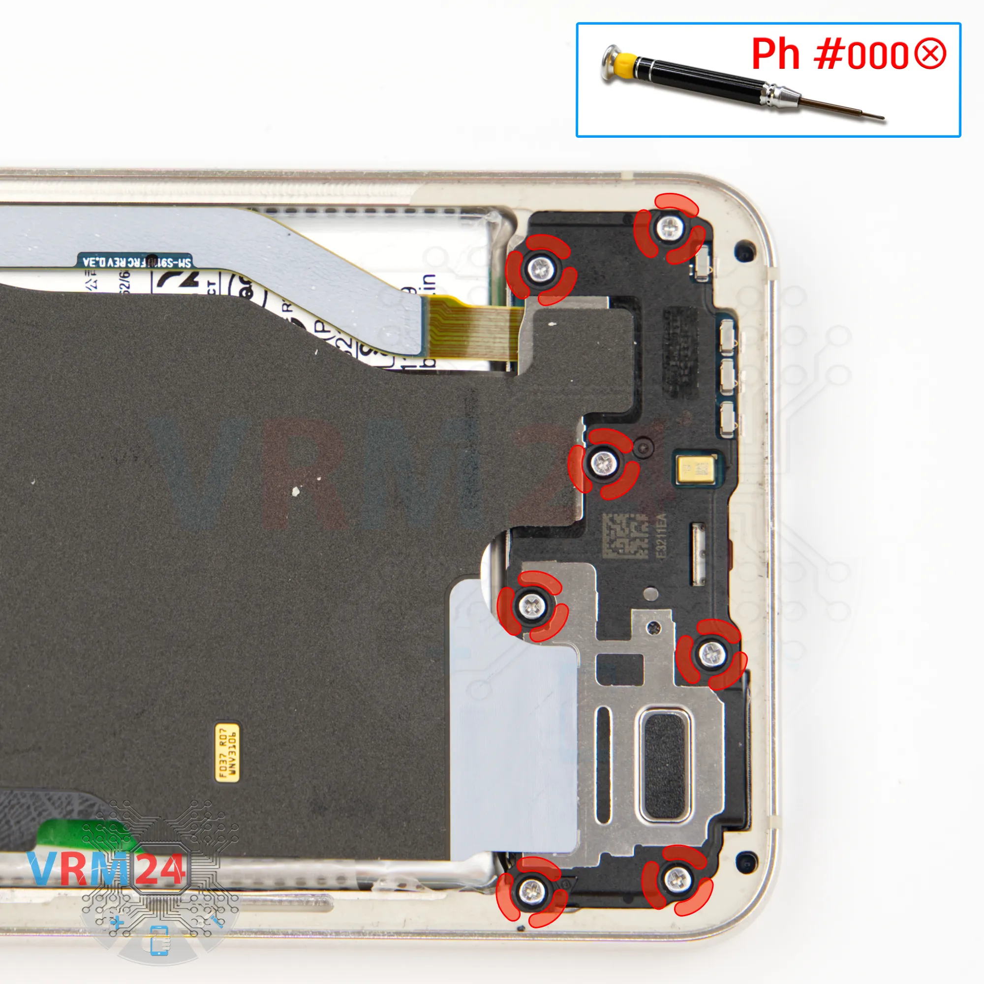
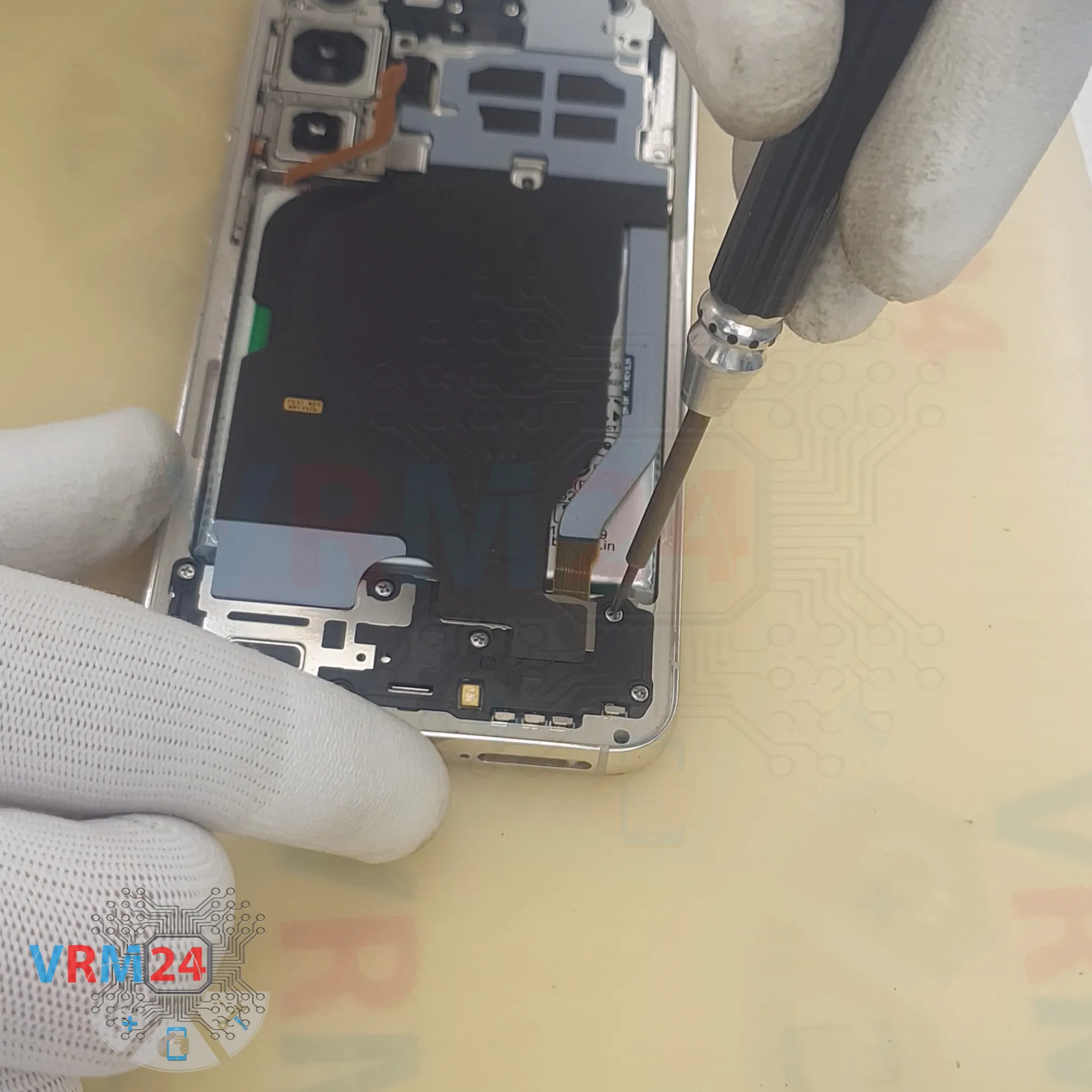
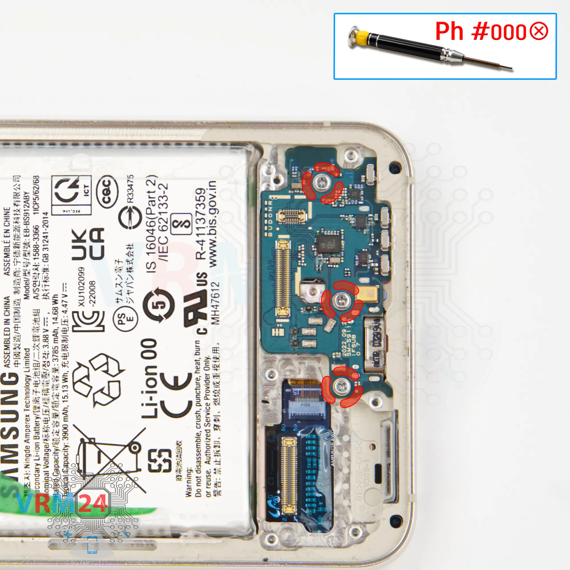
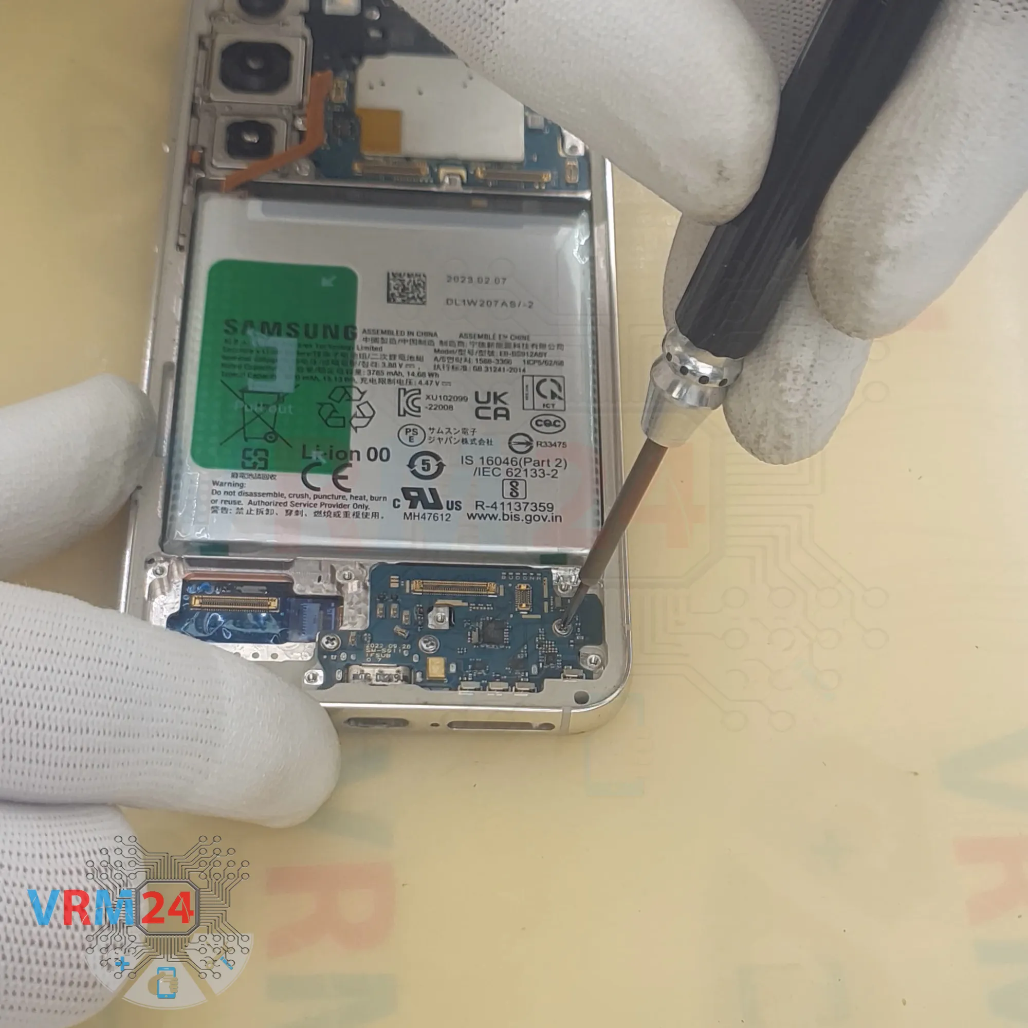
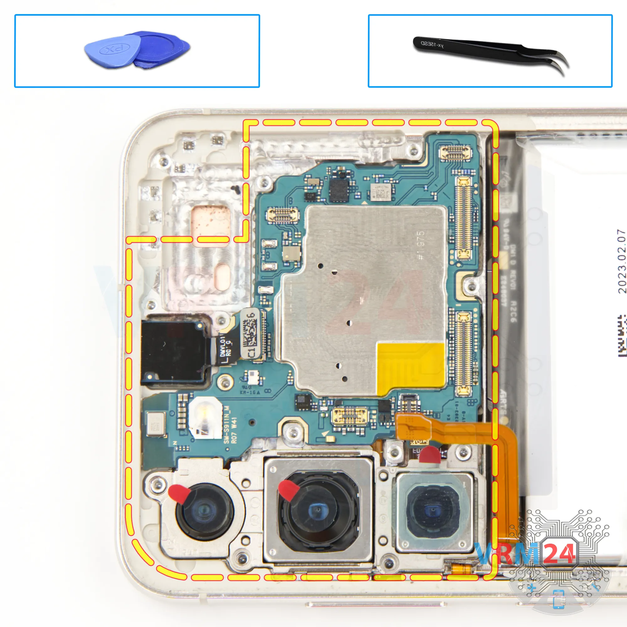
Step 11. Unscrew the screws
Once the flex cables are removed, we can move on to the sub-board.
We unscrew the three screws securing the sub-board. They look identical, but it’s still better to keep them separate from the others.
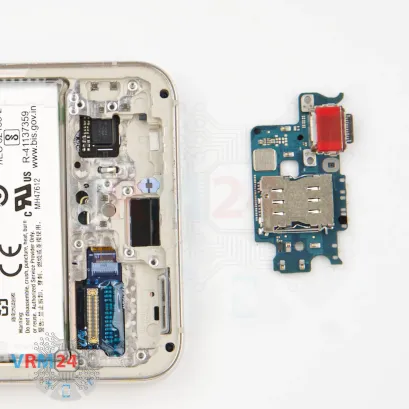


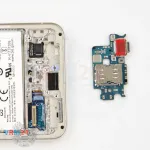
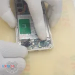
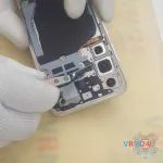
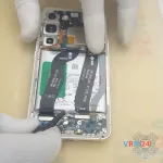
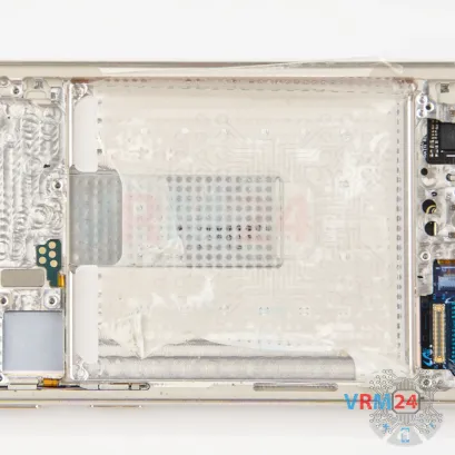
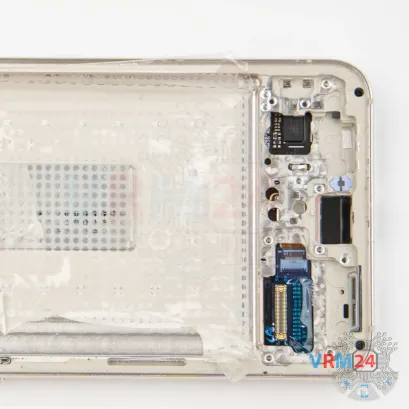
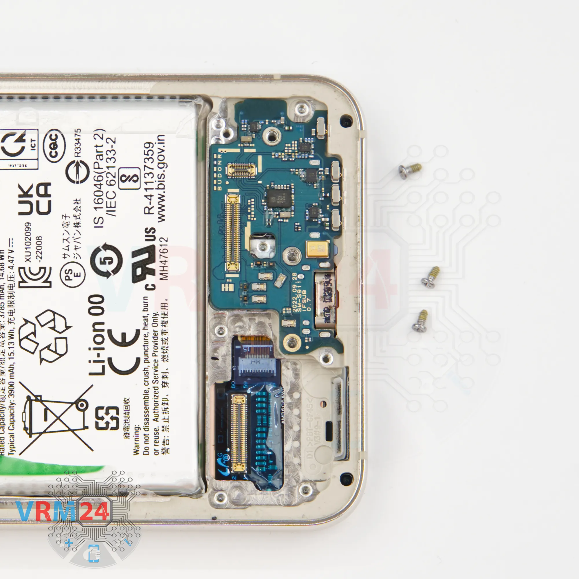
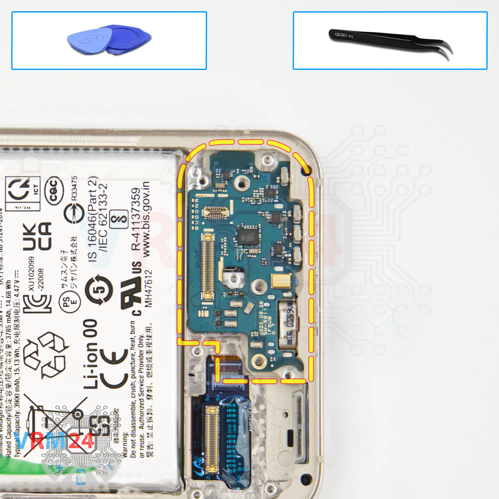
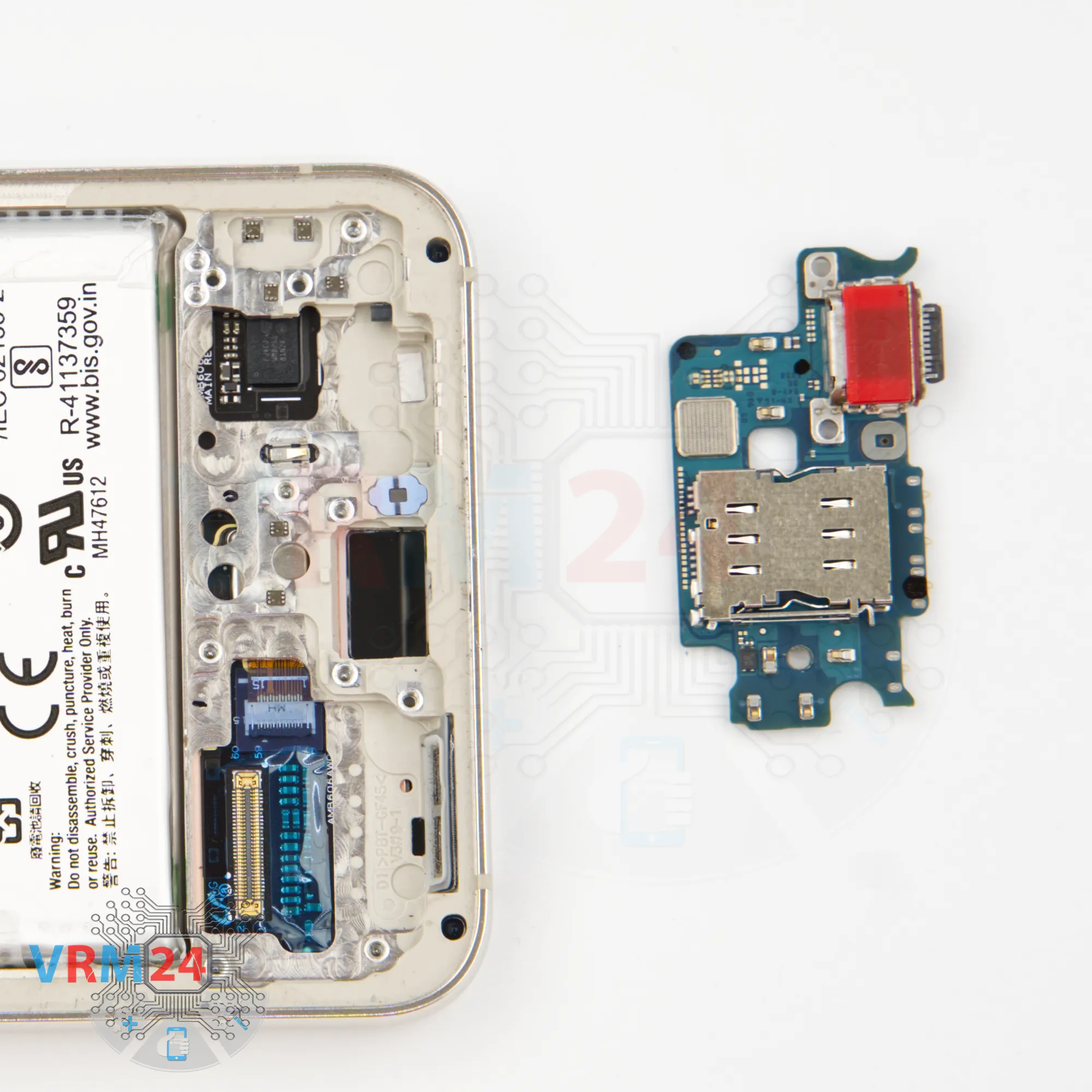
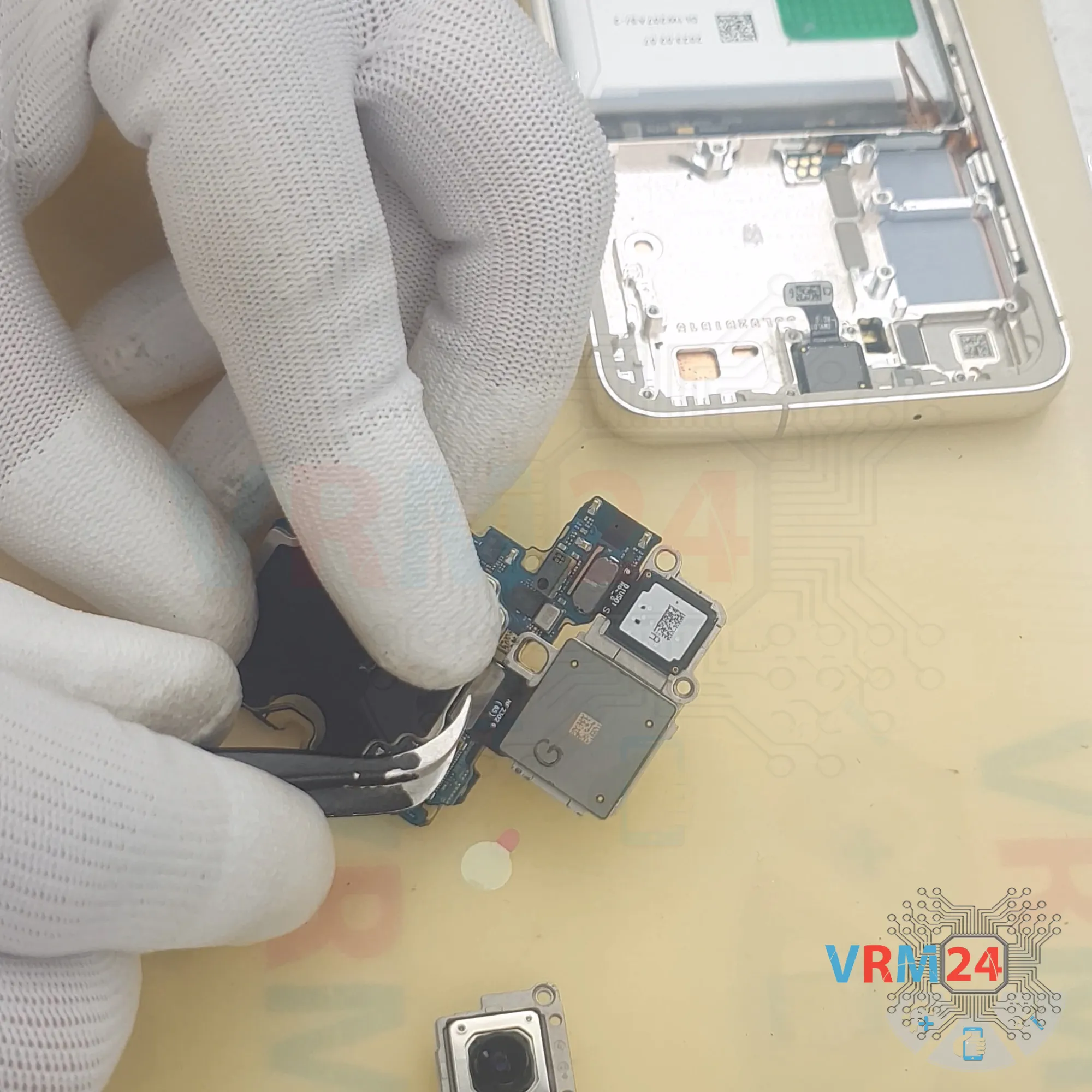
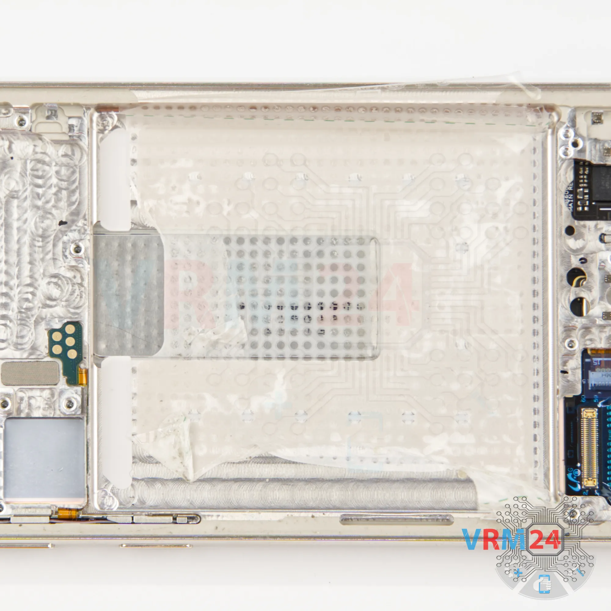
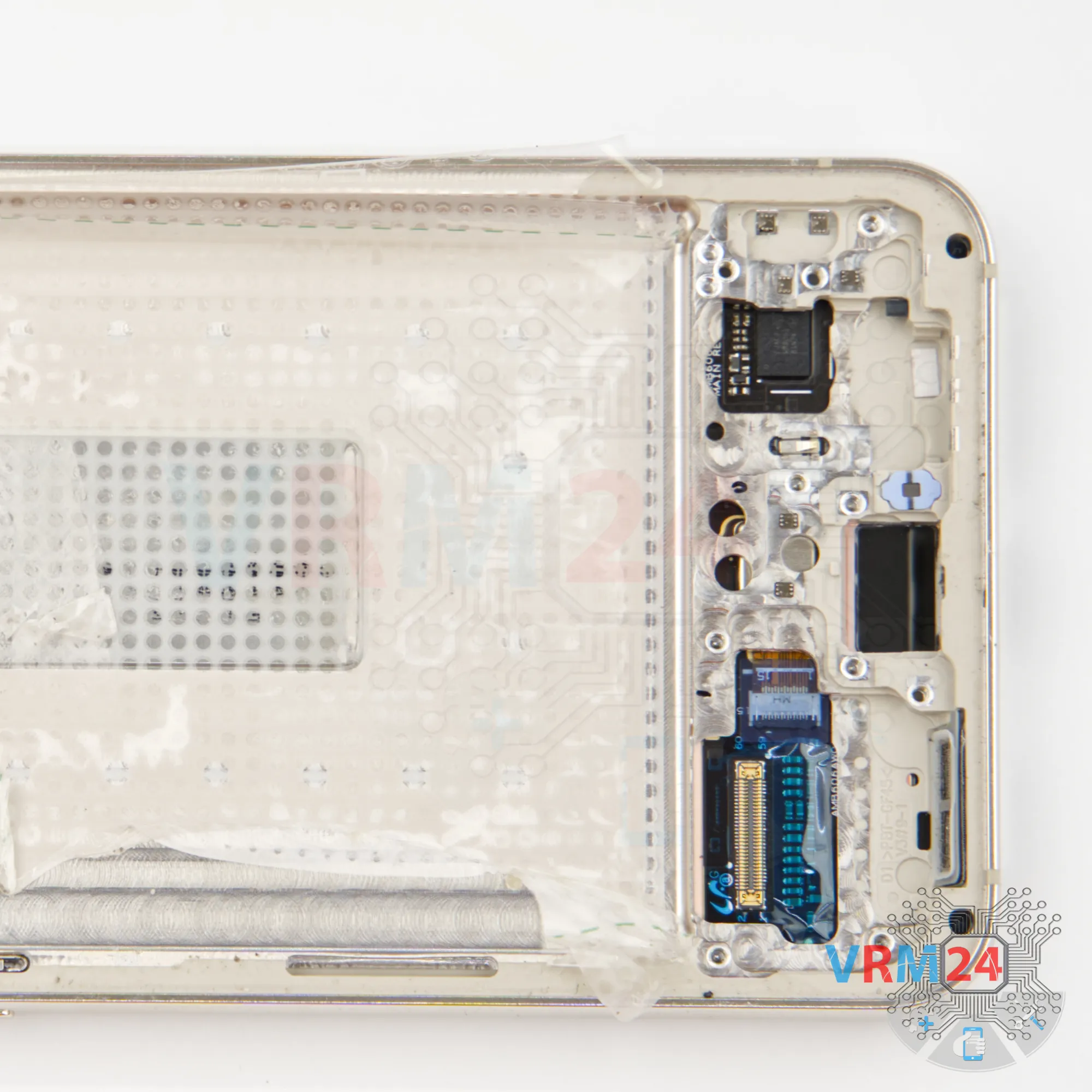
Step 12. Remove the sub-board
We carefully lift out the sub-board. It sits slightly recessed in the display frame, so take it out gently.
The sub-board contains the charging port, microphone, and the SIM connector is located on the other side.


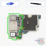
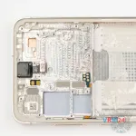
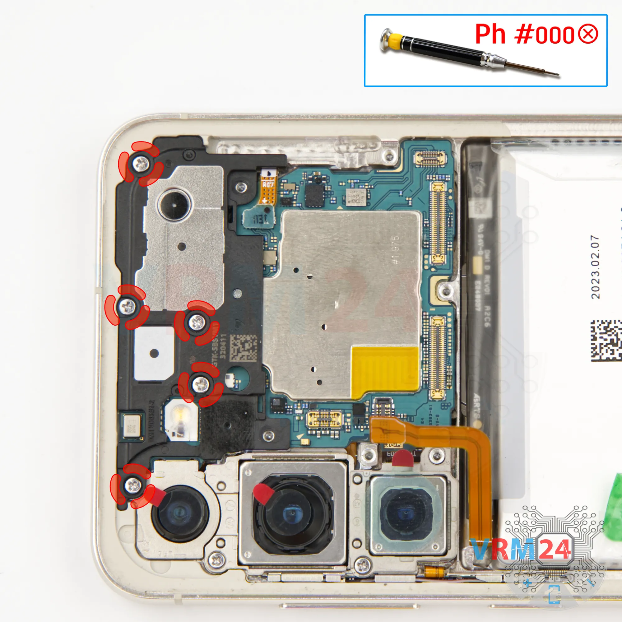
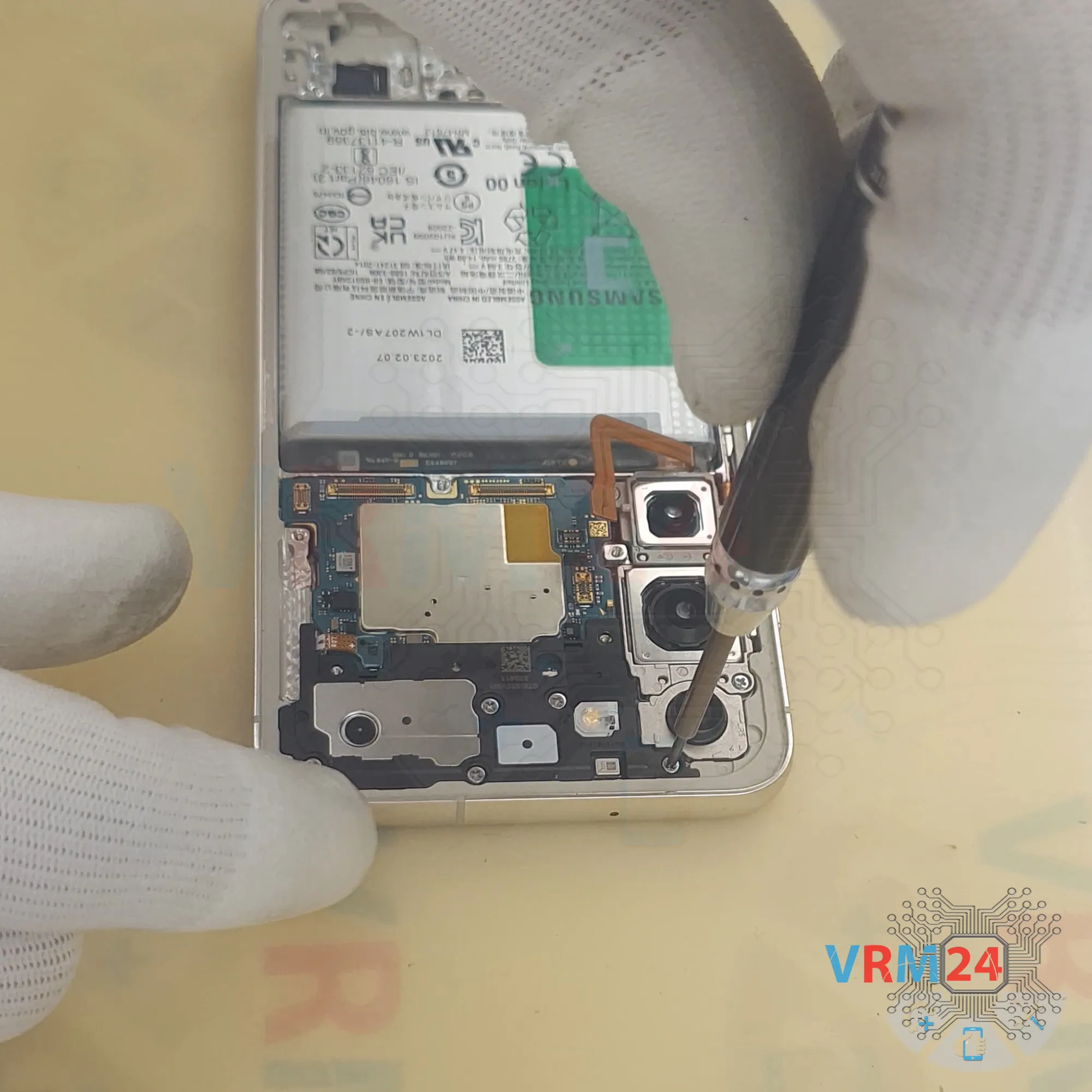
Step 13. Unscrew the screws
Now let’s move to the motherboard.
We need to remove the screws at the top that hold down the speaker cover and the motherboard.
Again, we use the 1.5 mm Phillips #000. Keep these screws separate as well.


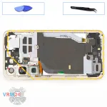
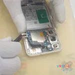
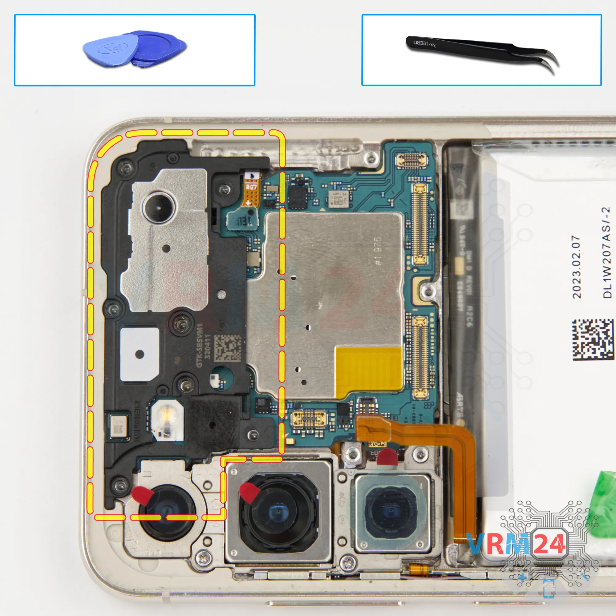
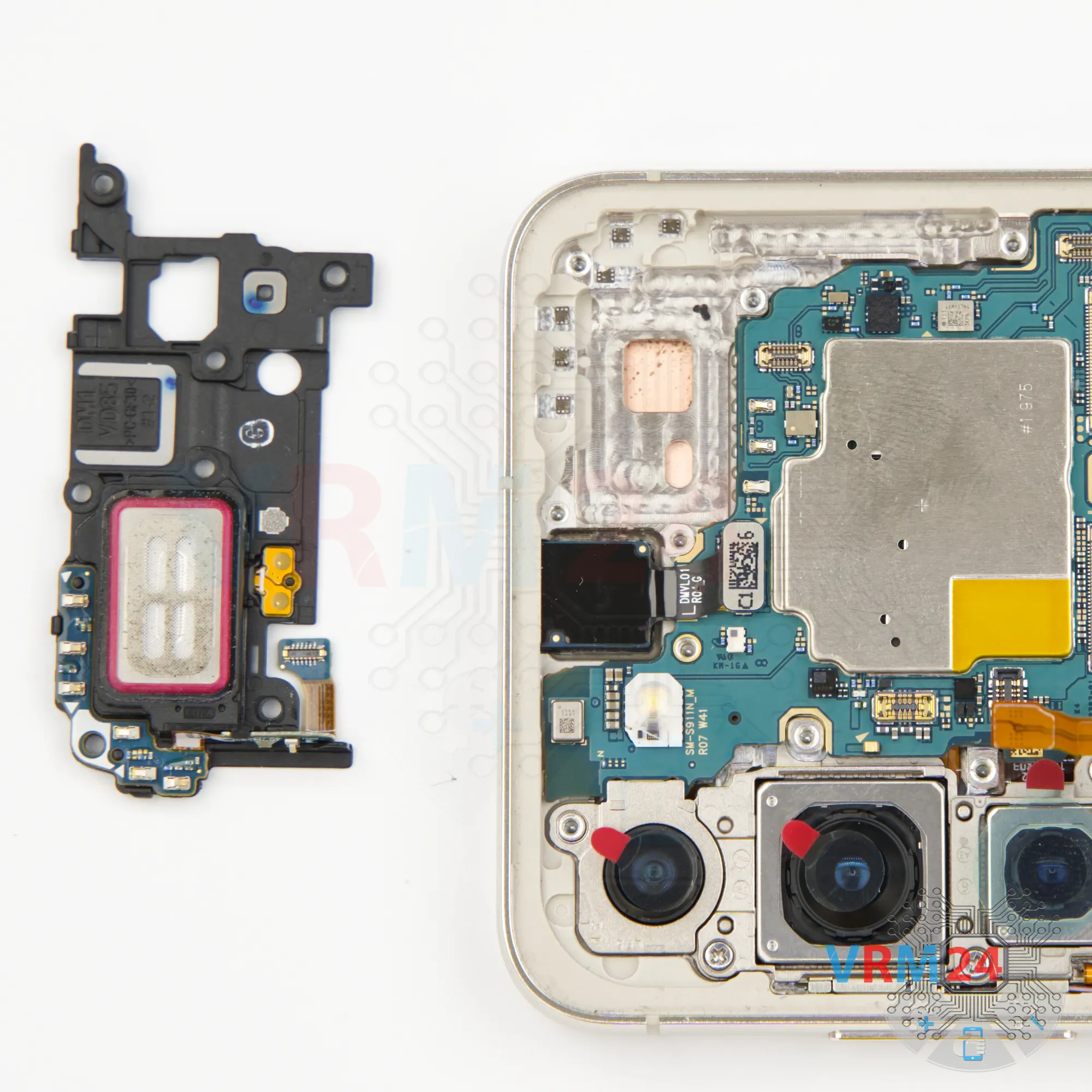
Step 14. Remove the earpiece speaker
We need to remove the top speaker cover. Gently pry it up at the edge, lift it, and remove it.


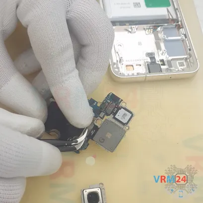
Step 16. Disconnect the connector
As we can see, under the cover we have the front-facing camera. Disconnect its connector.


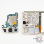
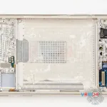
Step 17. Remove the motherboard
Carefully remove the printed circuit board. There is no need to use a lever or try to reach the circuit board by force. Make sure that nothing is getting in the way or holding the circuit board.
The motherboard, also, may be attached with attachments like latches or hooks, be careful.
⚠️️ Do not bend the circuit board when removing it or push tools under it. Unbeknownst to yourself, you can damage components or cables from the inside.
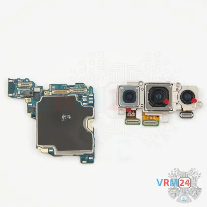
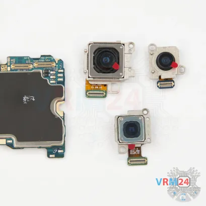
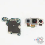
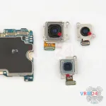

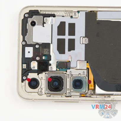
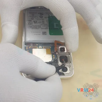
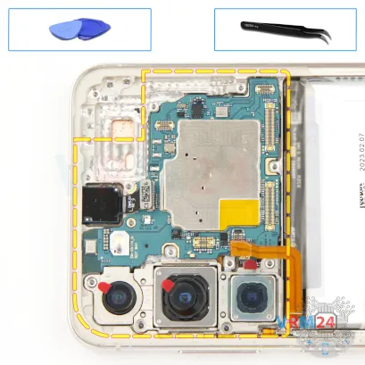
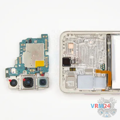
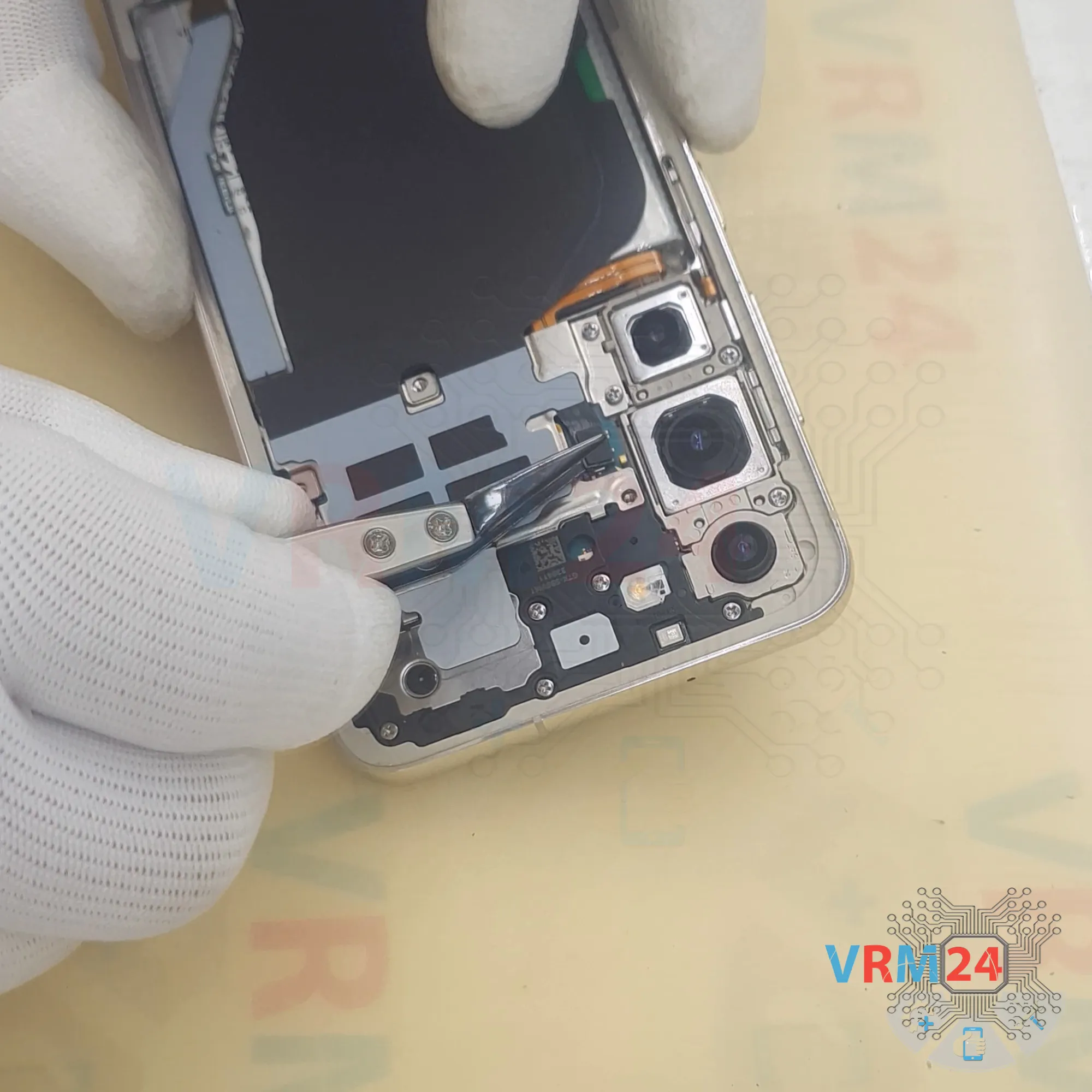
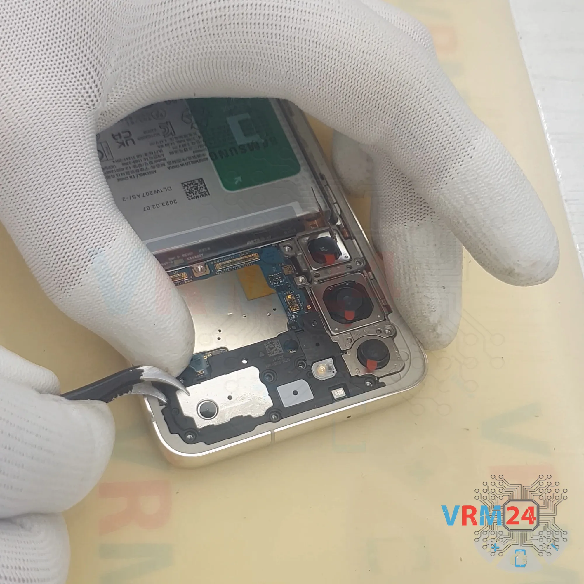
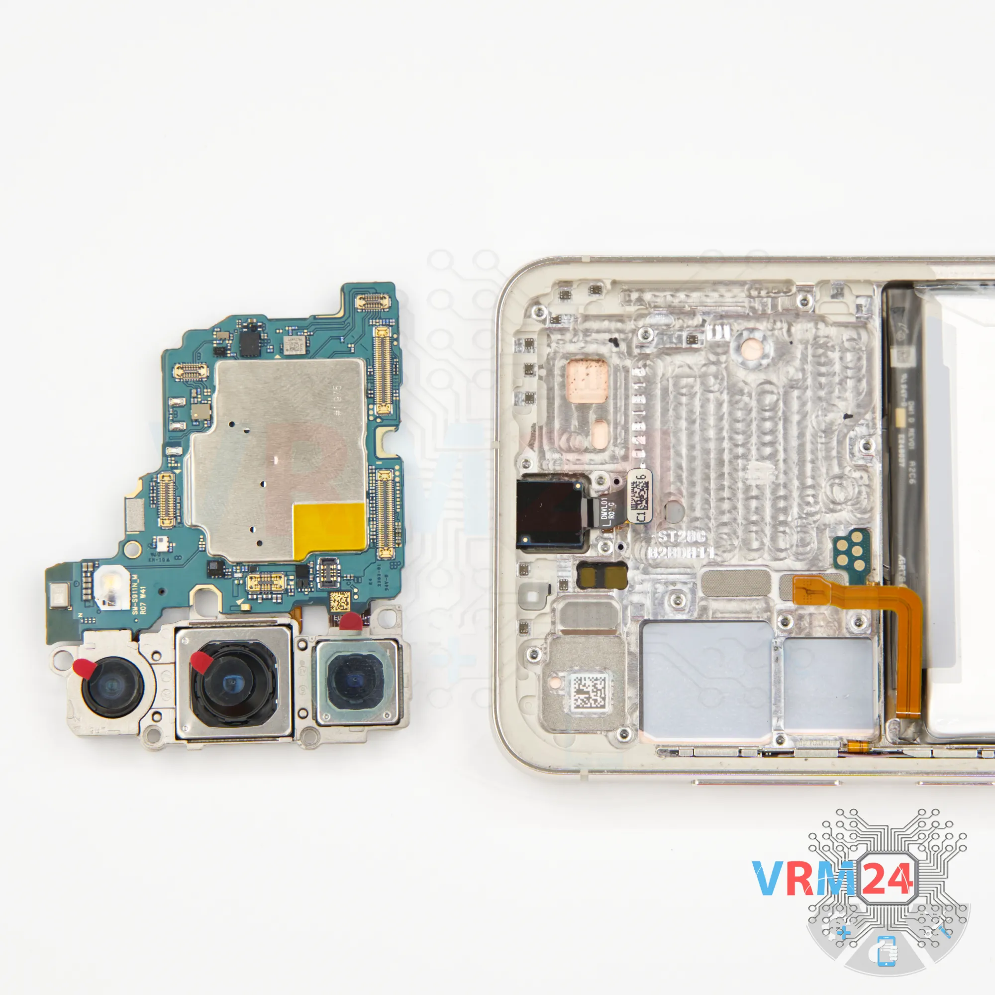
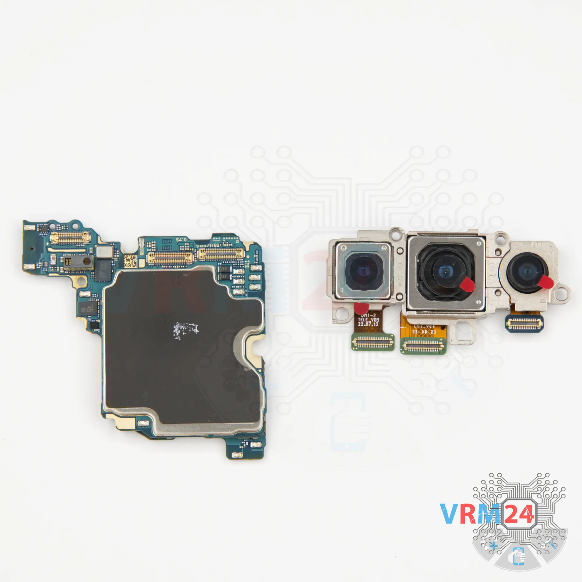
Step 18. Remove the cameras
Then we flip motherboard over to disconnect the rear cameras.
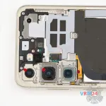
We disconnect the rear cameras and set them aside.
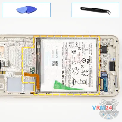


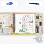
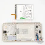

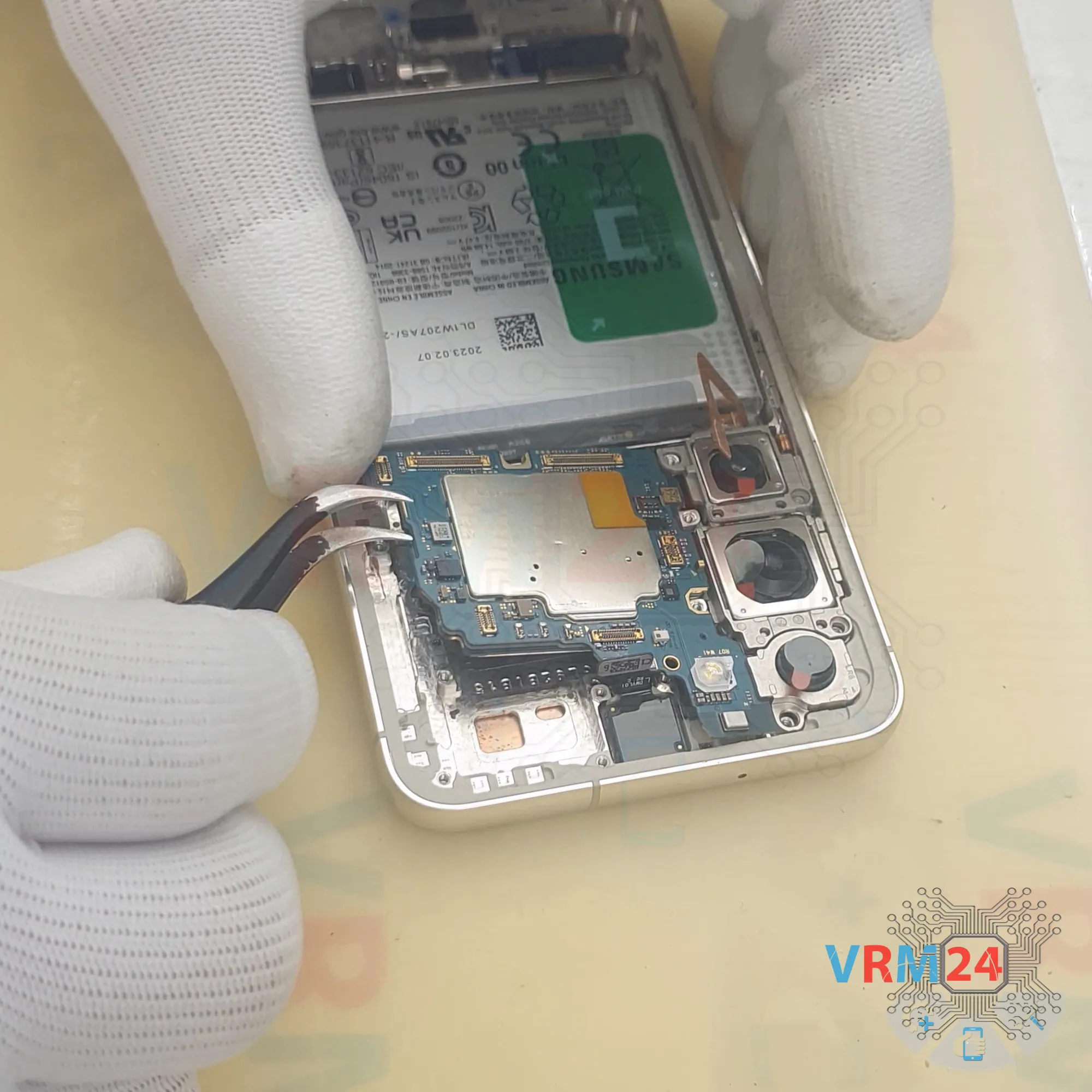
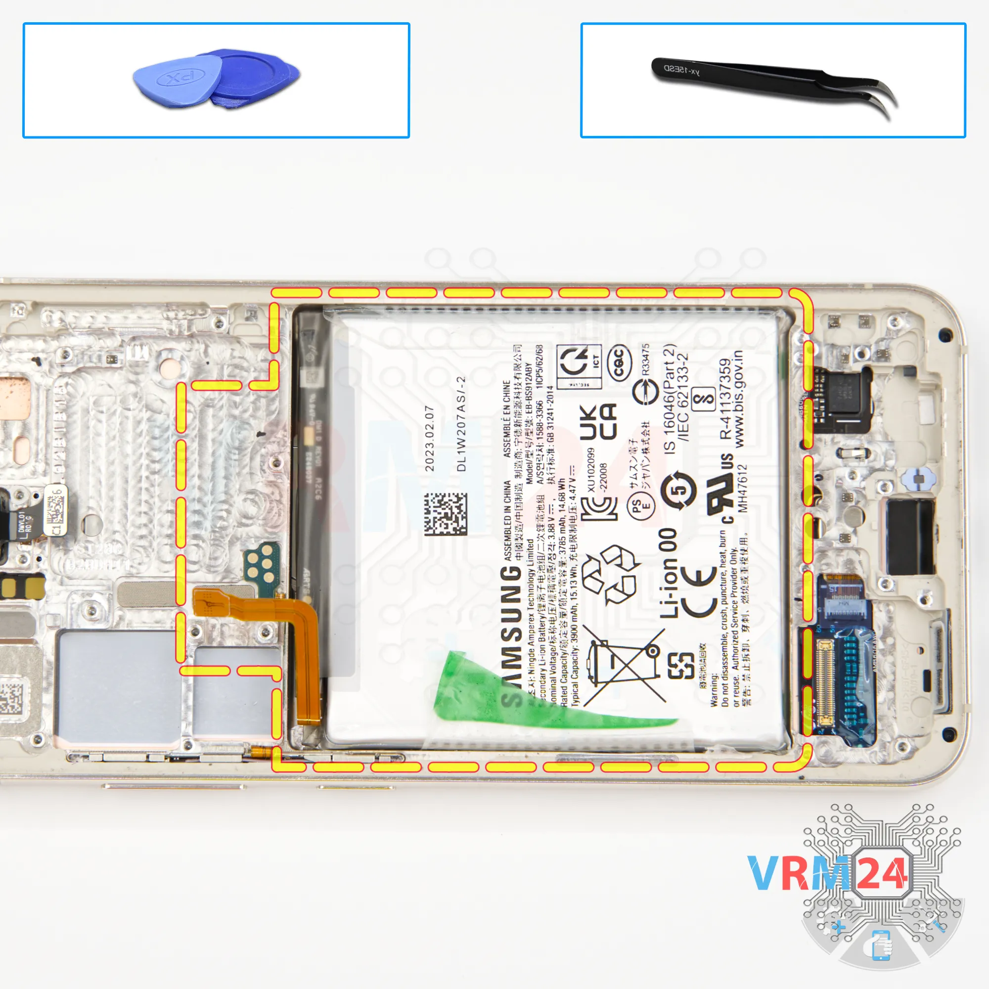
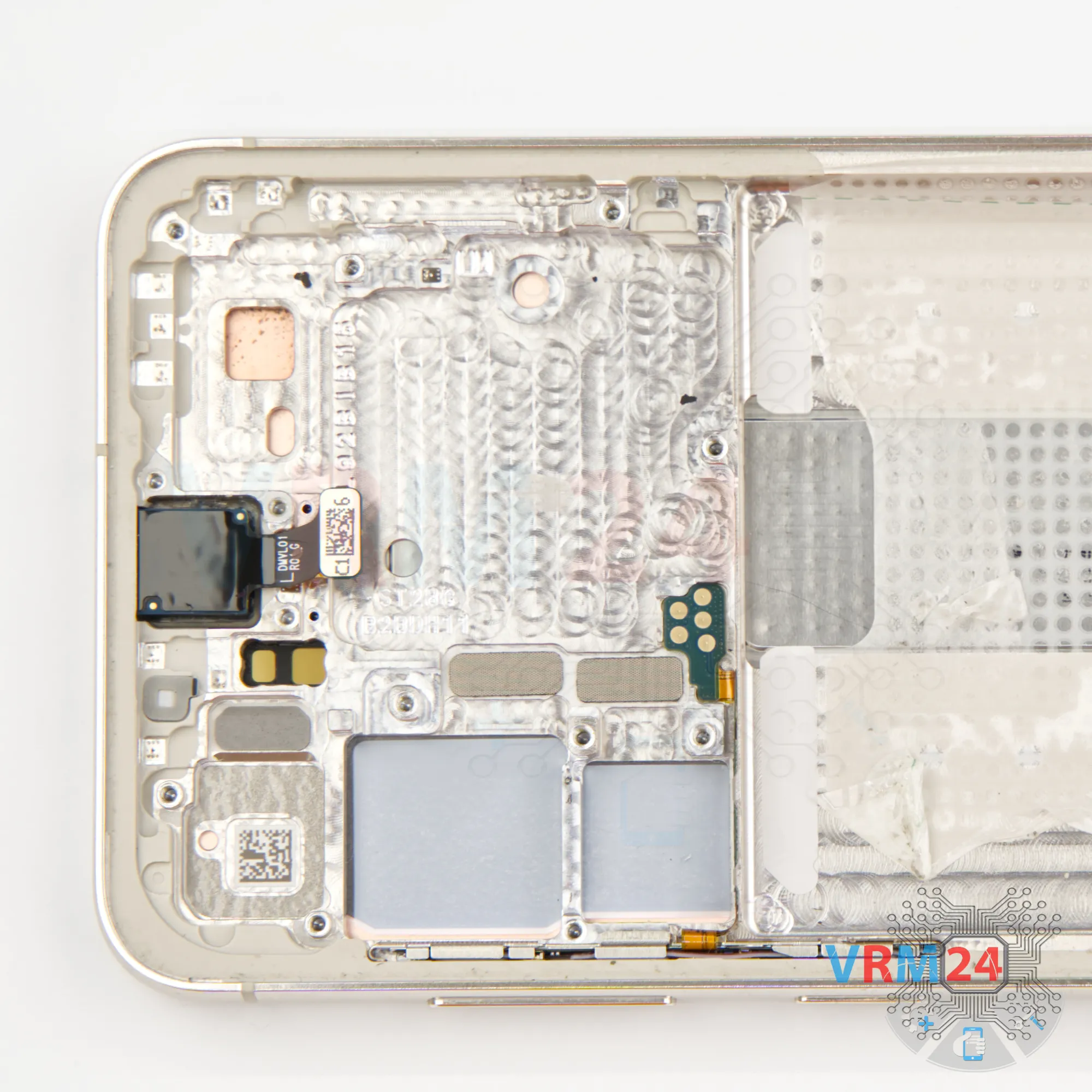
Step 19. Remove the battery
That leaves the battery.
As is typical for this Samsung series, there’s one green or blue pull tab in the middle. On the sides, there are clear films or tabs that you need to fold back as far as possible, then pull up on the center tab to release the battery.
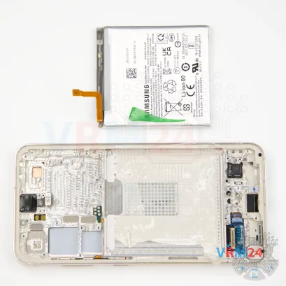
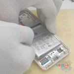
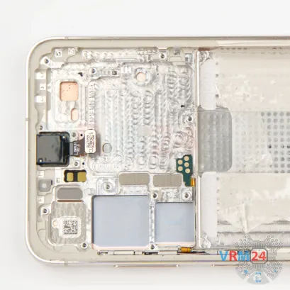
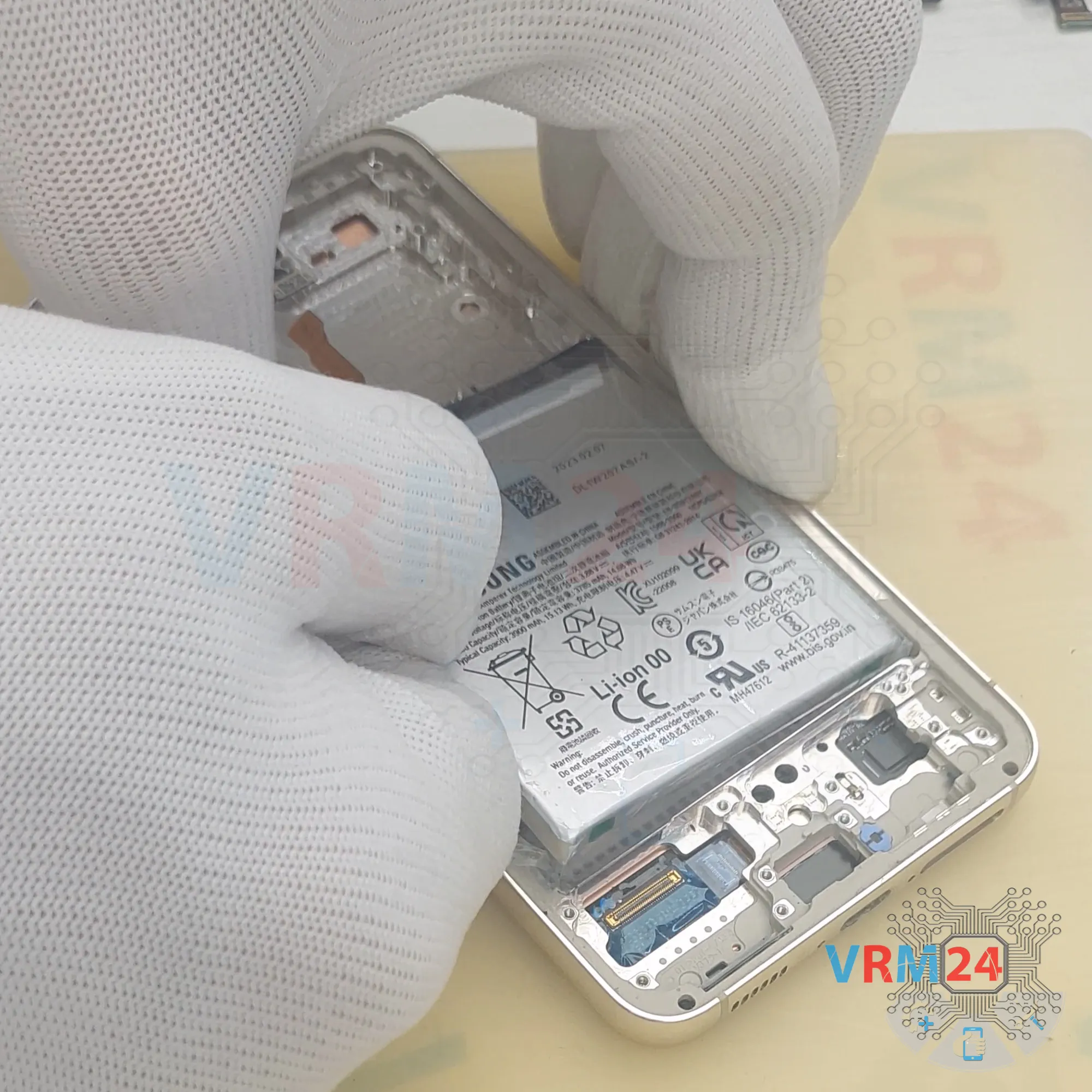
Also typical for this type of adhesive – part of the battery will likely be stuck more firmly in one area, usually because of heat from the battery or the display frame.
So, we need to find the spot where the battery is stuck. Carefully work it free using a plastic film and, if necessary, some isopropyl alcohol.
It’s best not to use a metal tool, since that could puncture the battery casing.
Once we separate the stuck spot, the rest of the battery will come out pretty easily.
Detailed disassembly instructions of Samsung Galaxy S23 SM-S911 in the video, made by our mobile repair & service center:
If you have a question, ask us, and we will try to answer in as much detail as possible. If this article was helpful for you, please rate it.

Disassembling\Repair has medium complexity and takes about minutes in time.
Our manual is suitable for all models Samsung Galaxy S23 SM-S911 — Samsung Galaxy S23 SM-S911B, SM-S911B/DS, SM-S911U, SM-S911U1, SM-S911W, SM-S911N, SM-S9110, SM-S911E, SM-S911E/DS released for markets in different countries.
Back to the list