

⚠️️ Before disassembling, do not forget to turn your phone off.
Teardown difficulty:
Moderate
Moderate
Recommended tools


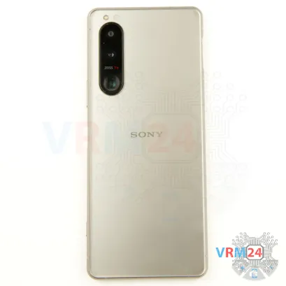
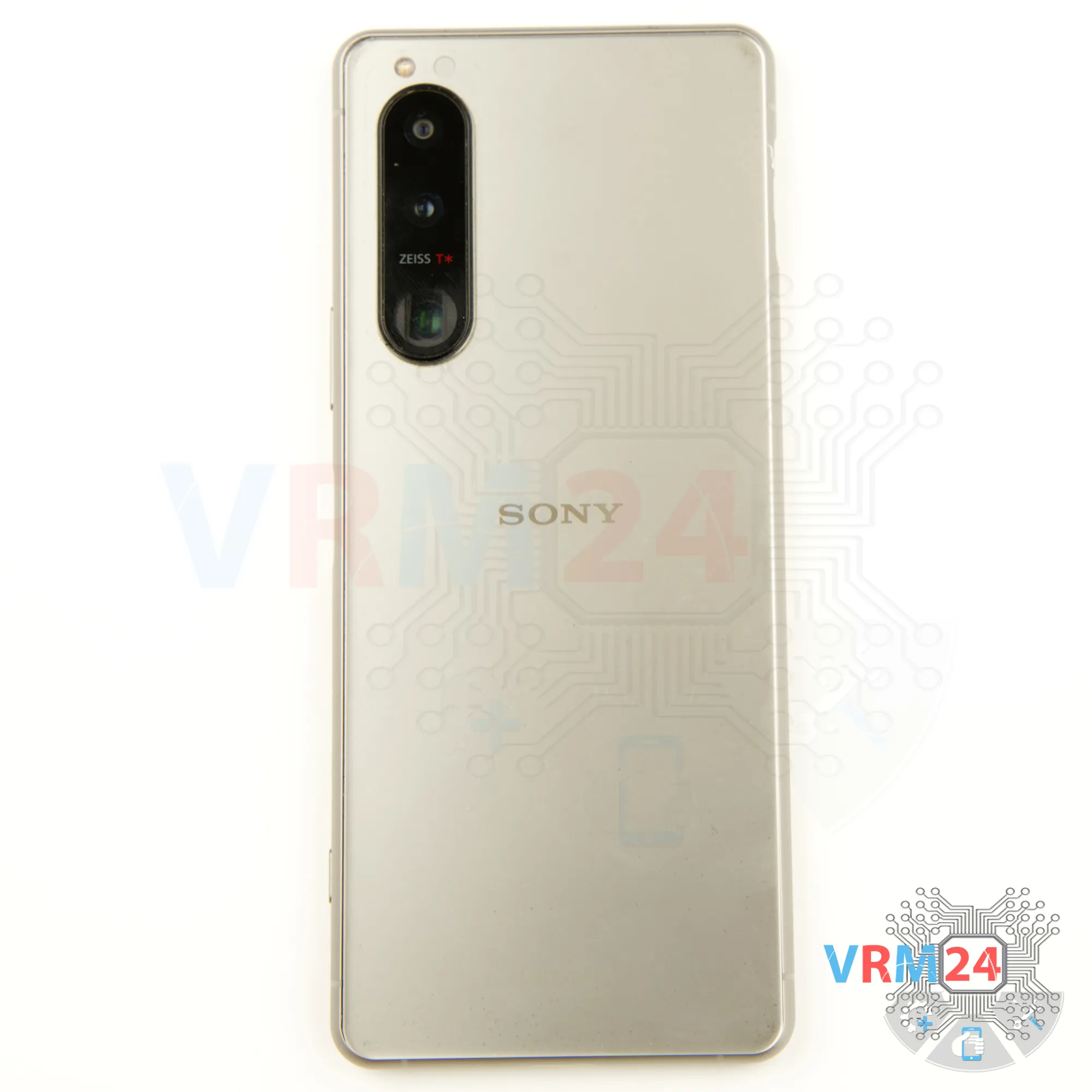
Disassembly/Repair of the mobile device Sony Xperia 5 III (Sony Xperia 5 III XQ BQ62/G) with each step description and the required set of tools.


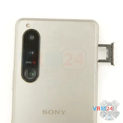

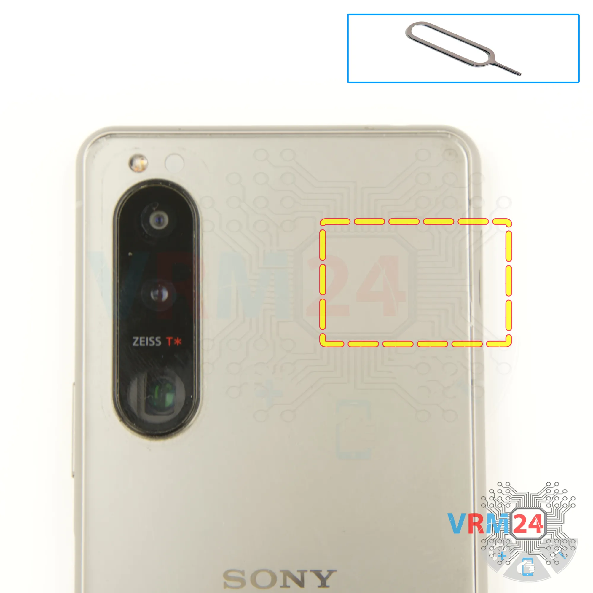
Step 2. Remove the tray
To remove the tray we Insert our fingernail or a thin, non-metallic object (like a plastic card) into the notch and gently pull the tray out.
Be careful not to force it to avoid damaging the tray or the slot.
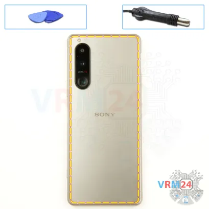

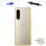
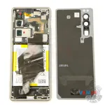
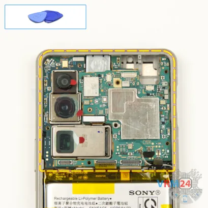
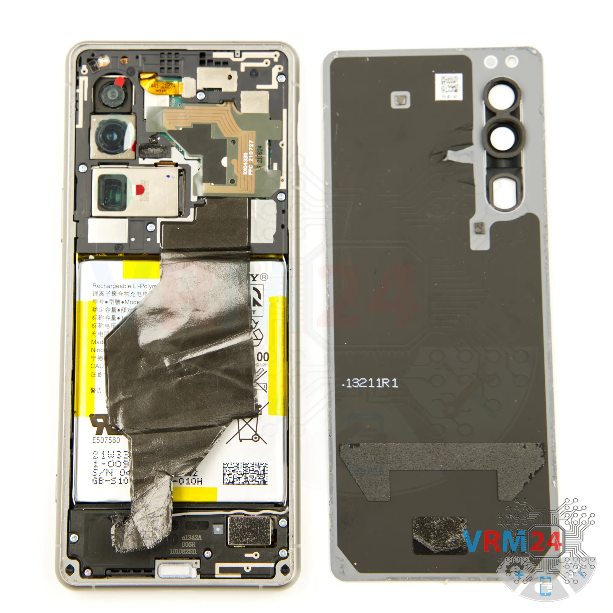
Step 3. Open the back cover
Warm the cover to approximately 50°C (160°F) using a heating mat or hair dryer. This softens the adhesive.
Employ a flexible plastic film (like a screen protector or a similar item from a stationery store) as a tool.
Insert the film into the gap between the back cover and the middle frame. Gently slide it around the edges to cut through the adhesive.
⚠️️ Take extra care near the side buttons and camera module to avoid damage.
⚠️️ Do not push the tool too far under the cover, as internal components could be damaged.

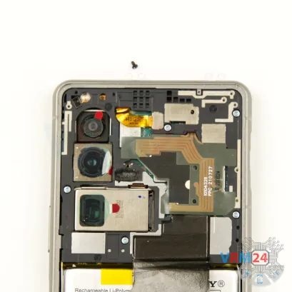

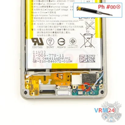
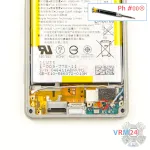
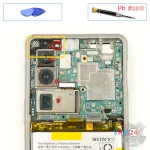
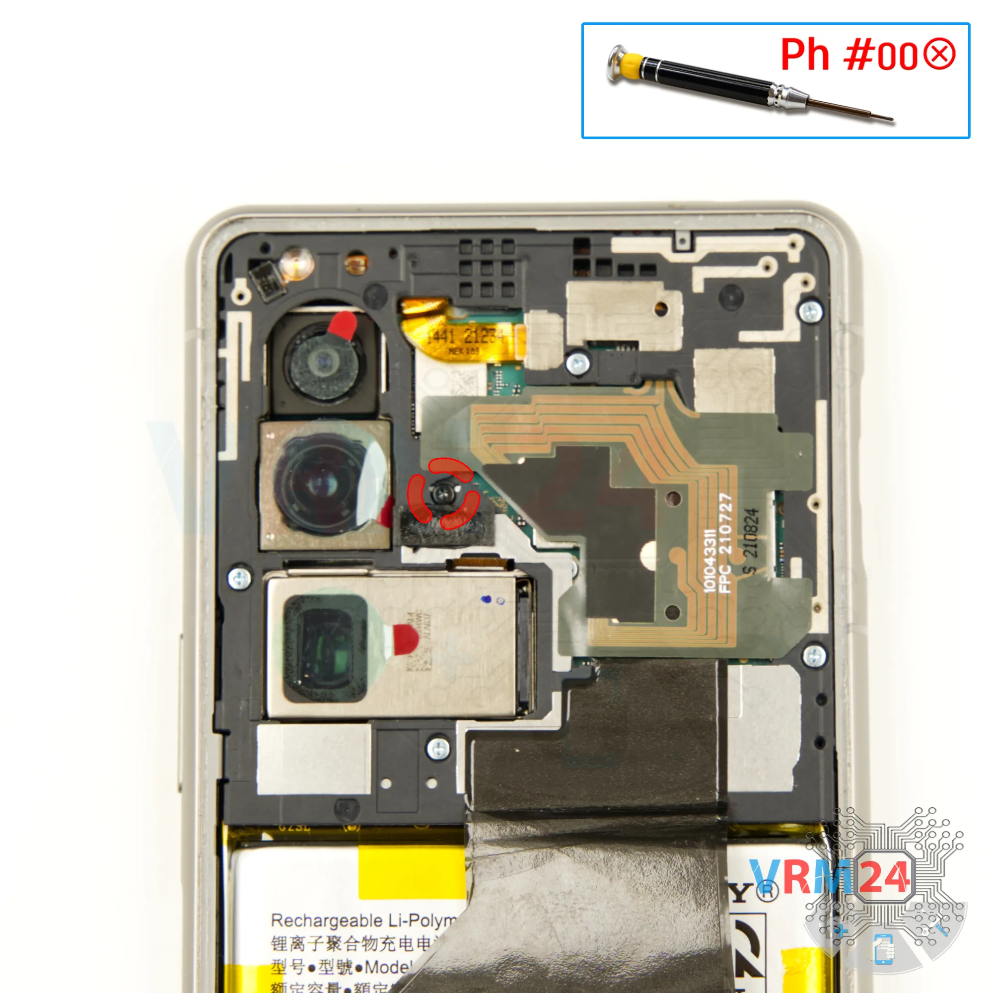
Step 4. Unscrew one screw
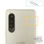
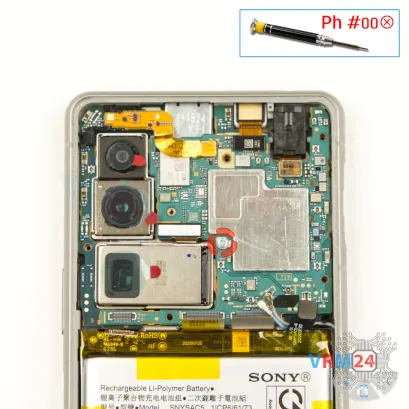
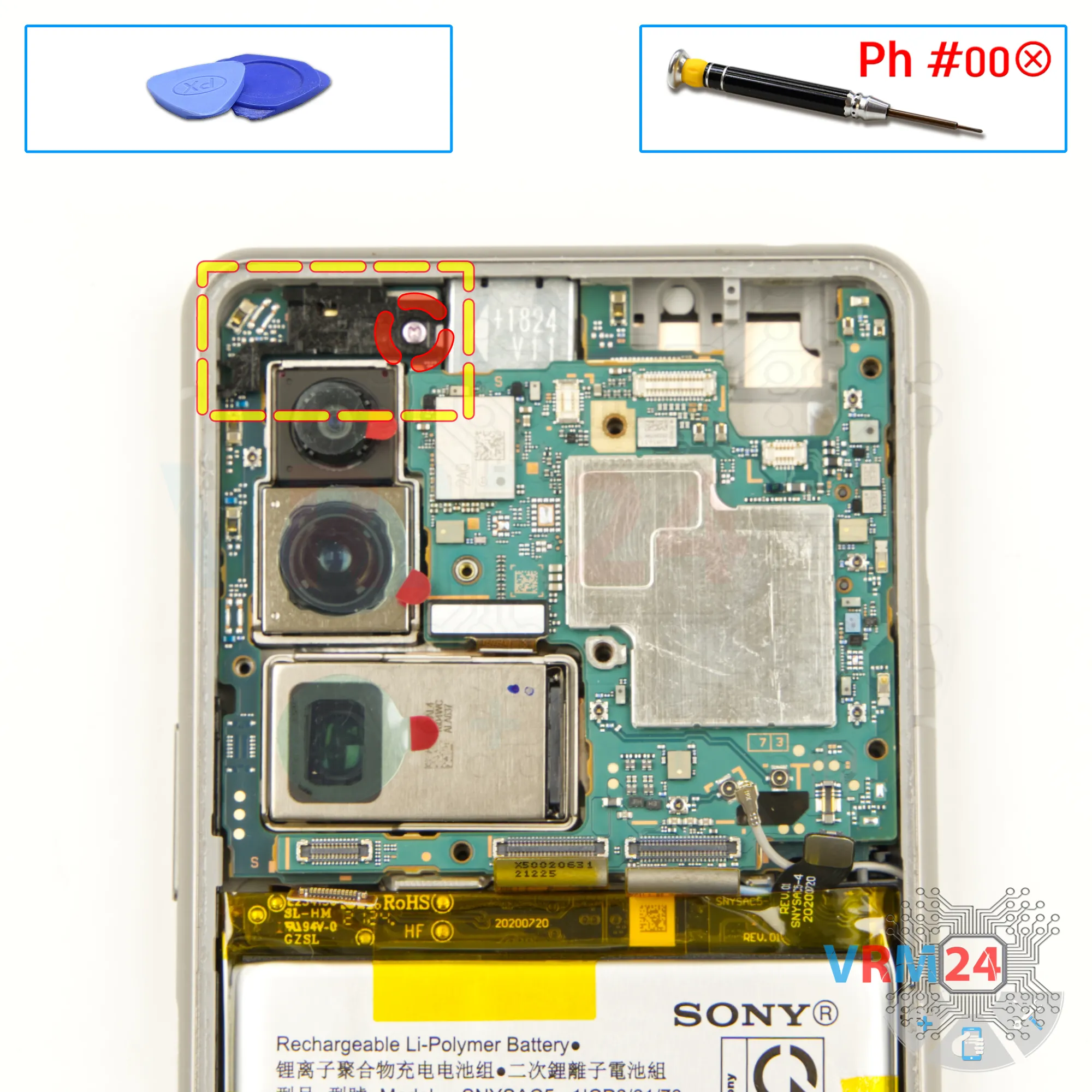
First, it's a good idea to cover the camera lenses to protect them. Use a special film or a similar material to shield the lenses. Make sure the lenses are fully covered to prevent dust or any debris from getting on them.
Next, you’ll need to unscrew the screws at the top section of the device. Use a 1.5-millimeter Phillips screwdriver or a Phillips #000 for this.
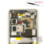
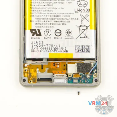
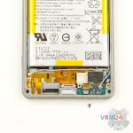
Carefully unscrew one screw in the middle.
This one in the middle is a different size and color. If you accidentally insert a different screw into that hole, you could risk damaging the motherboard.
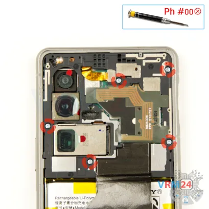

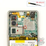
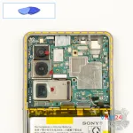
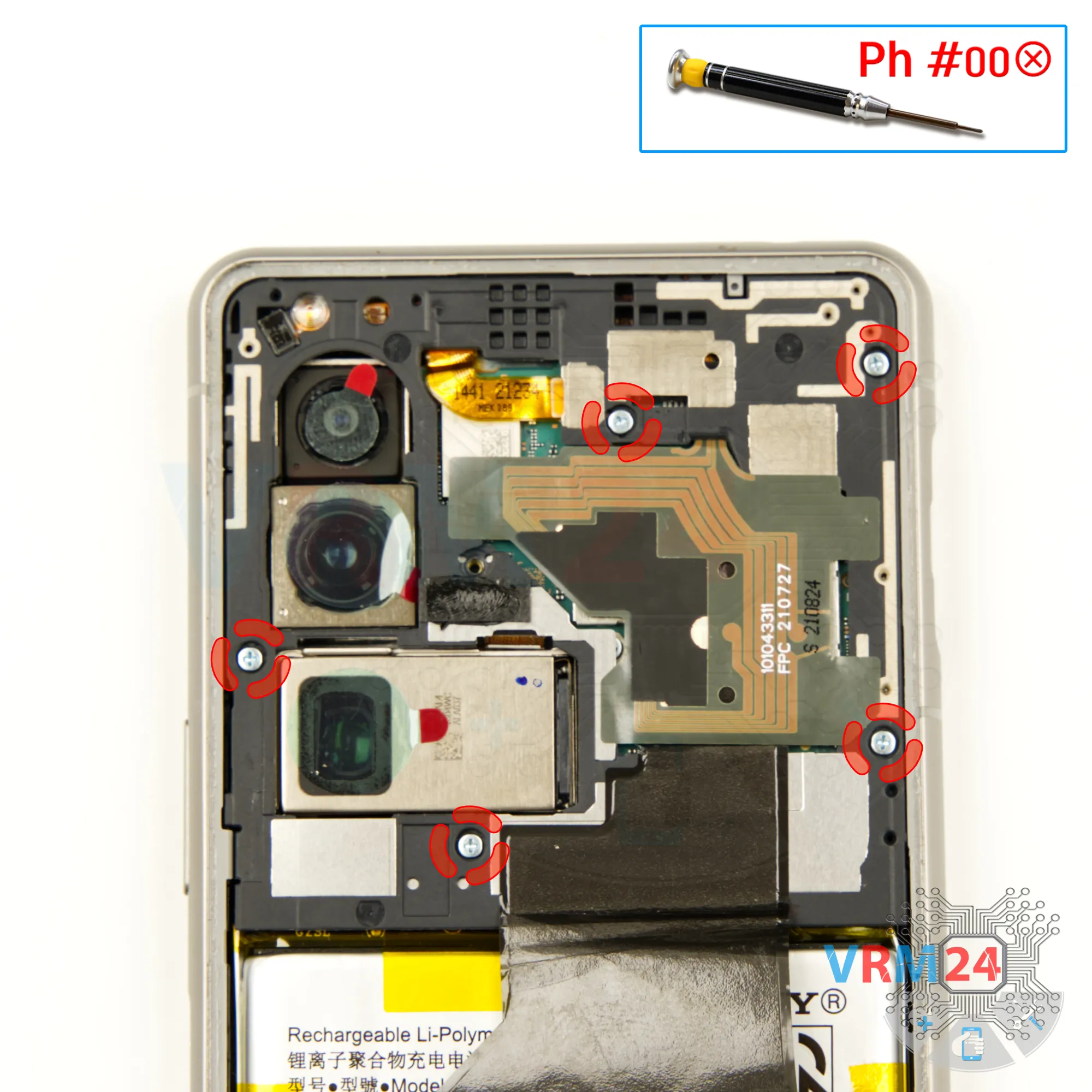
Step 5. Unscrew the screws
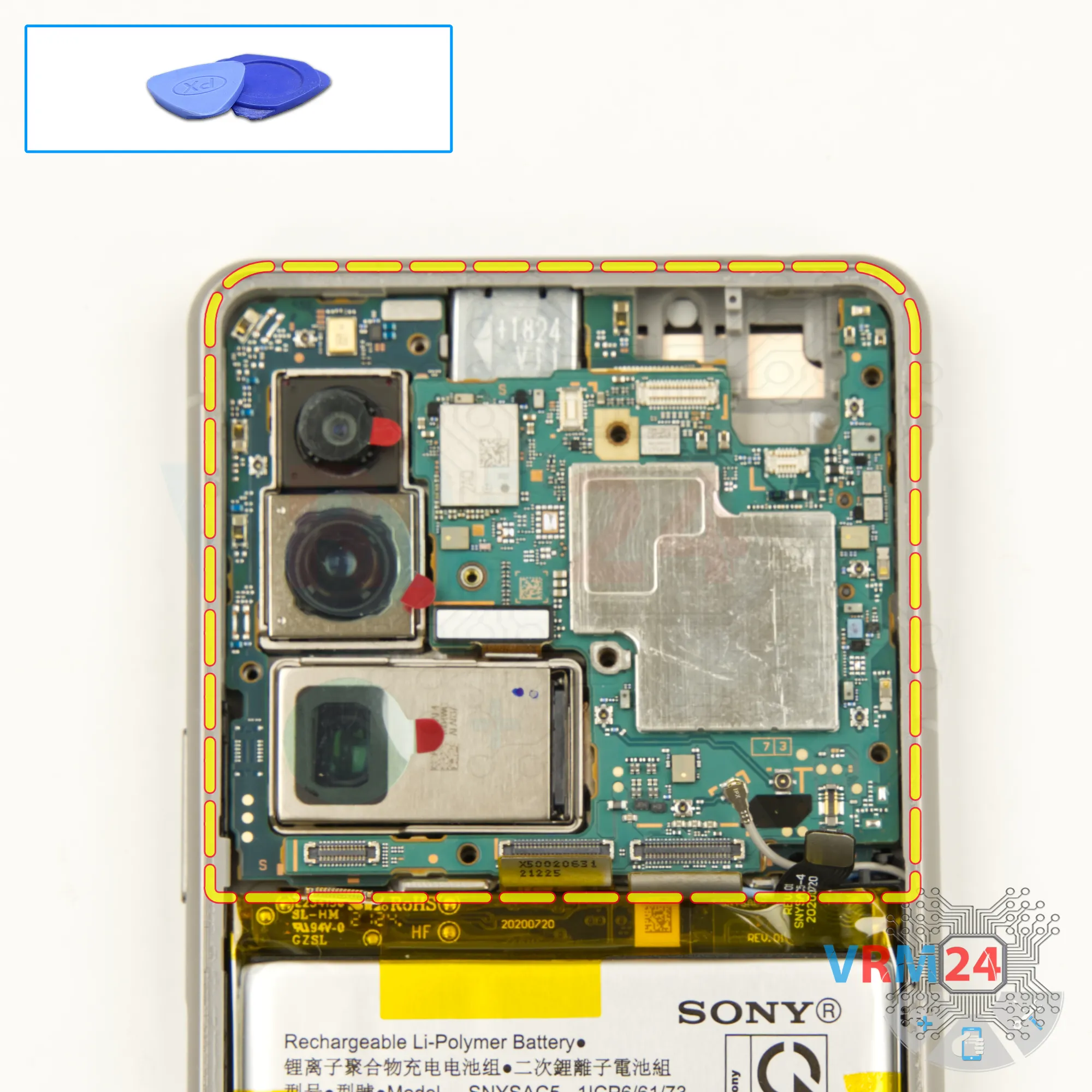
Using a 1.5-millimeter Phillips screwdriver or a Phillips #000 carefully unscrew the screws one by one and place them in an organized manner on a flat surface, so you don’t mix them up during reassembly.

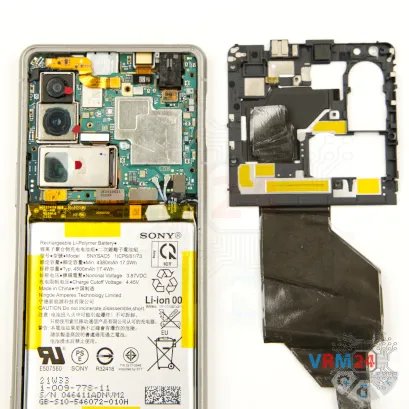
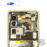
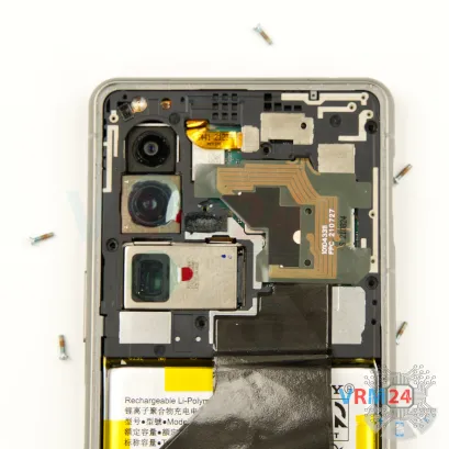
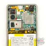
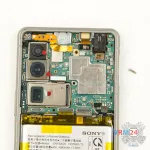
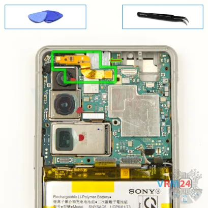
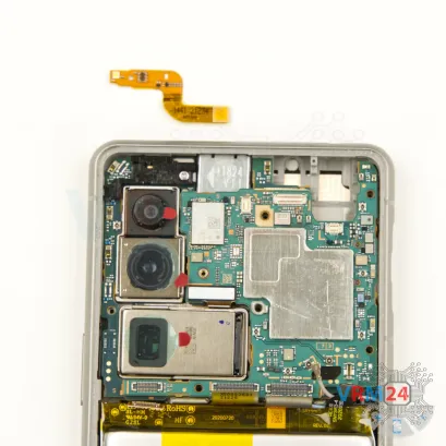
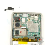
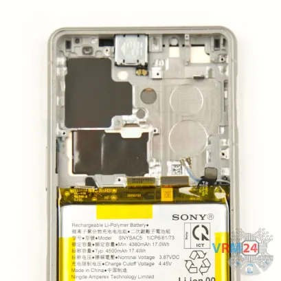
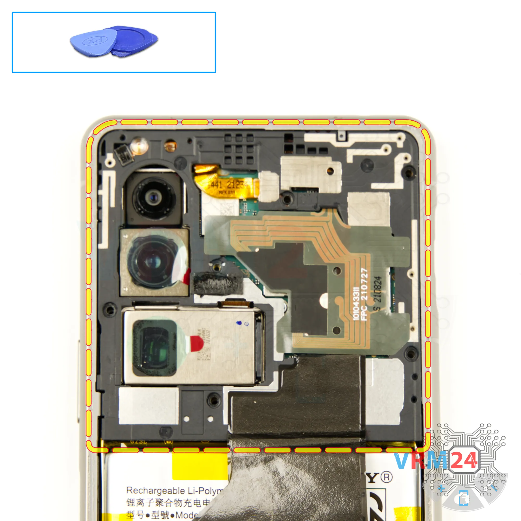
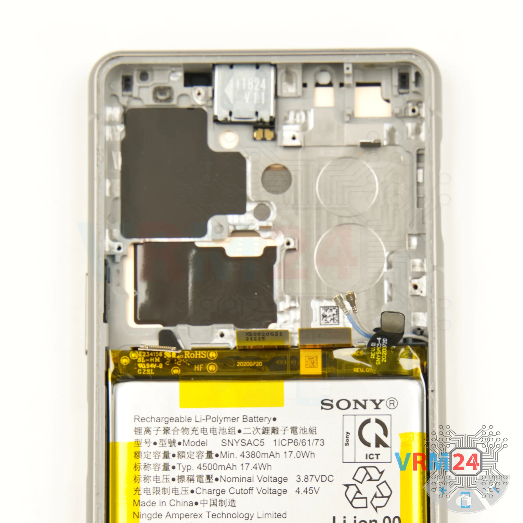
Step 6. Open the cover
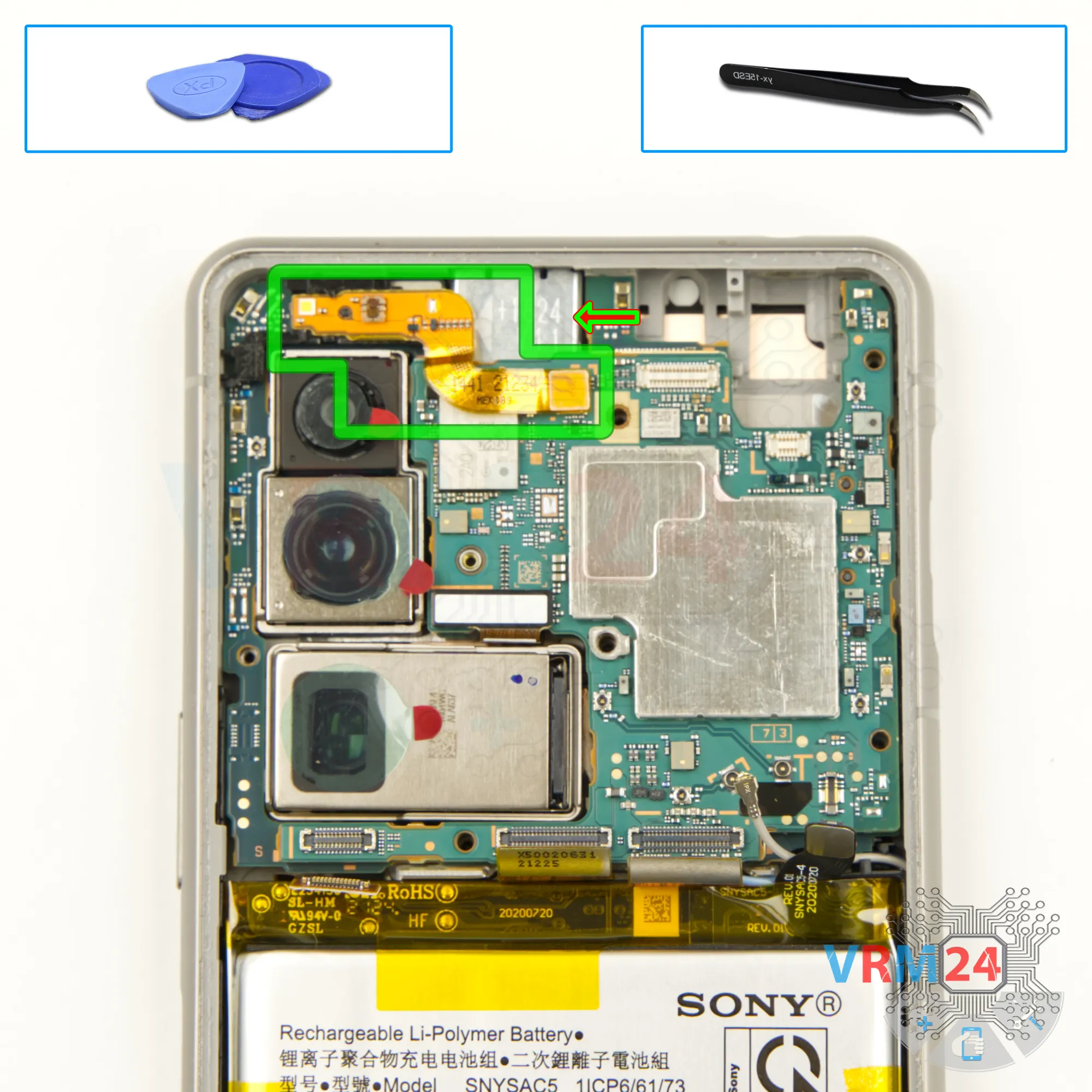
Next, we need to make sure nothing is obstructing our work before removing the cover that protects the motherboard. This is the cover with the antenna transmission lines.
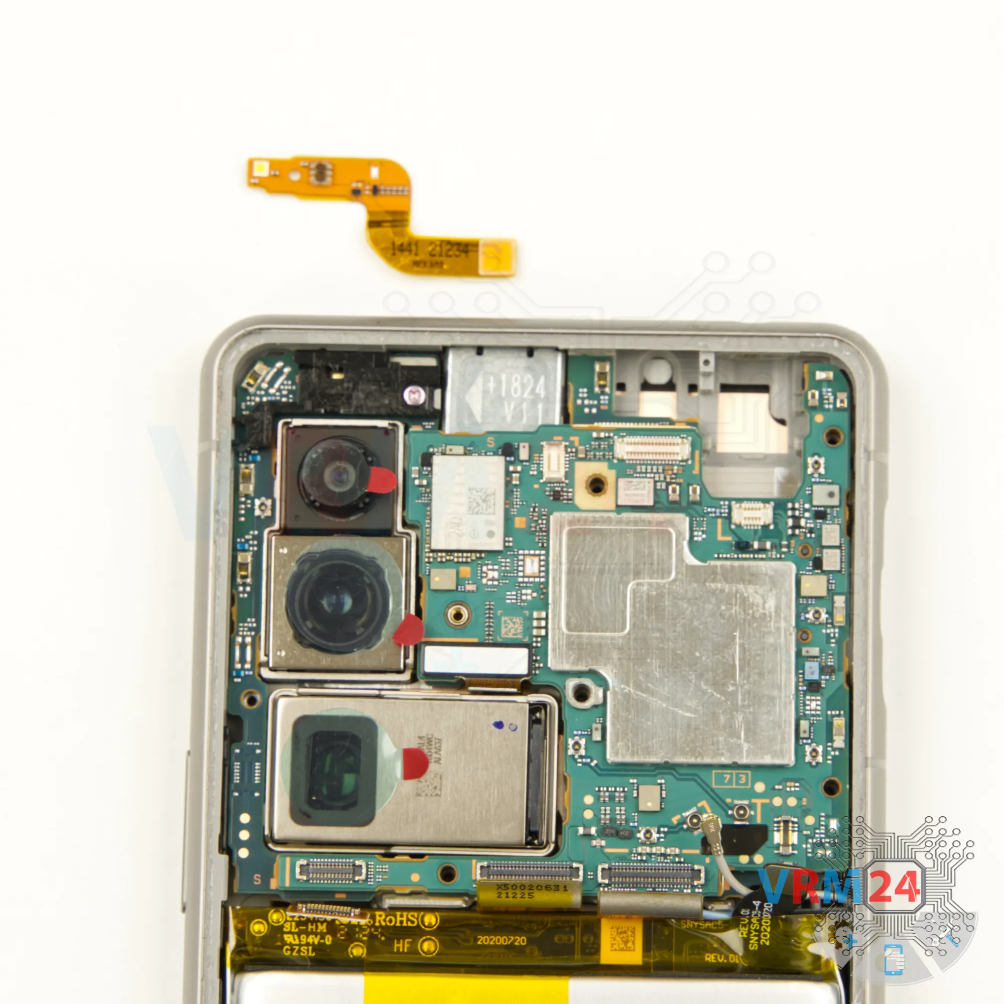
Carefully lift the edge, then gently pull it away to detach the cover. There's no need to rush or use excessive force—take your time to avoid damaging anything.

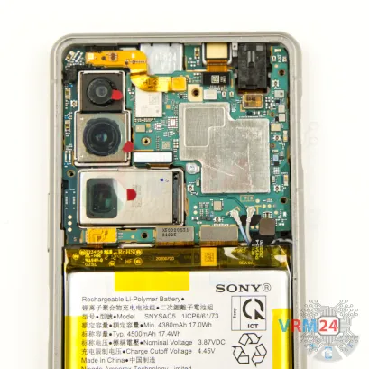
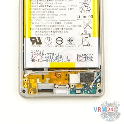
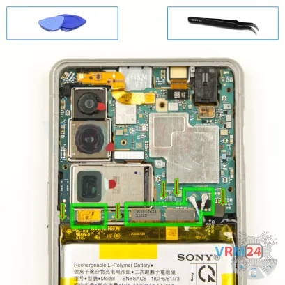
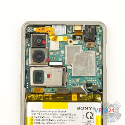
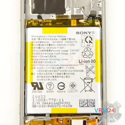
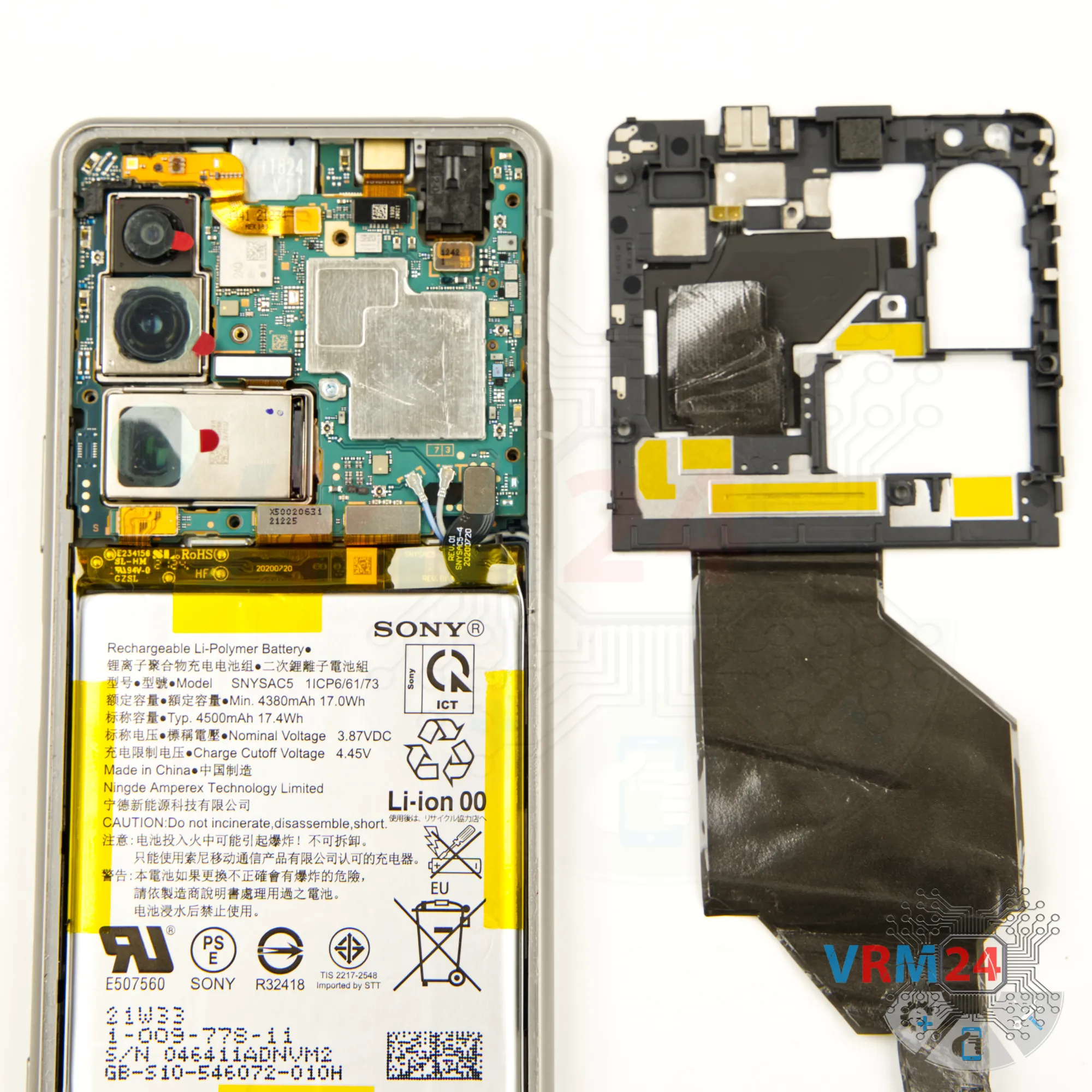
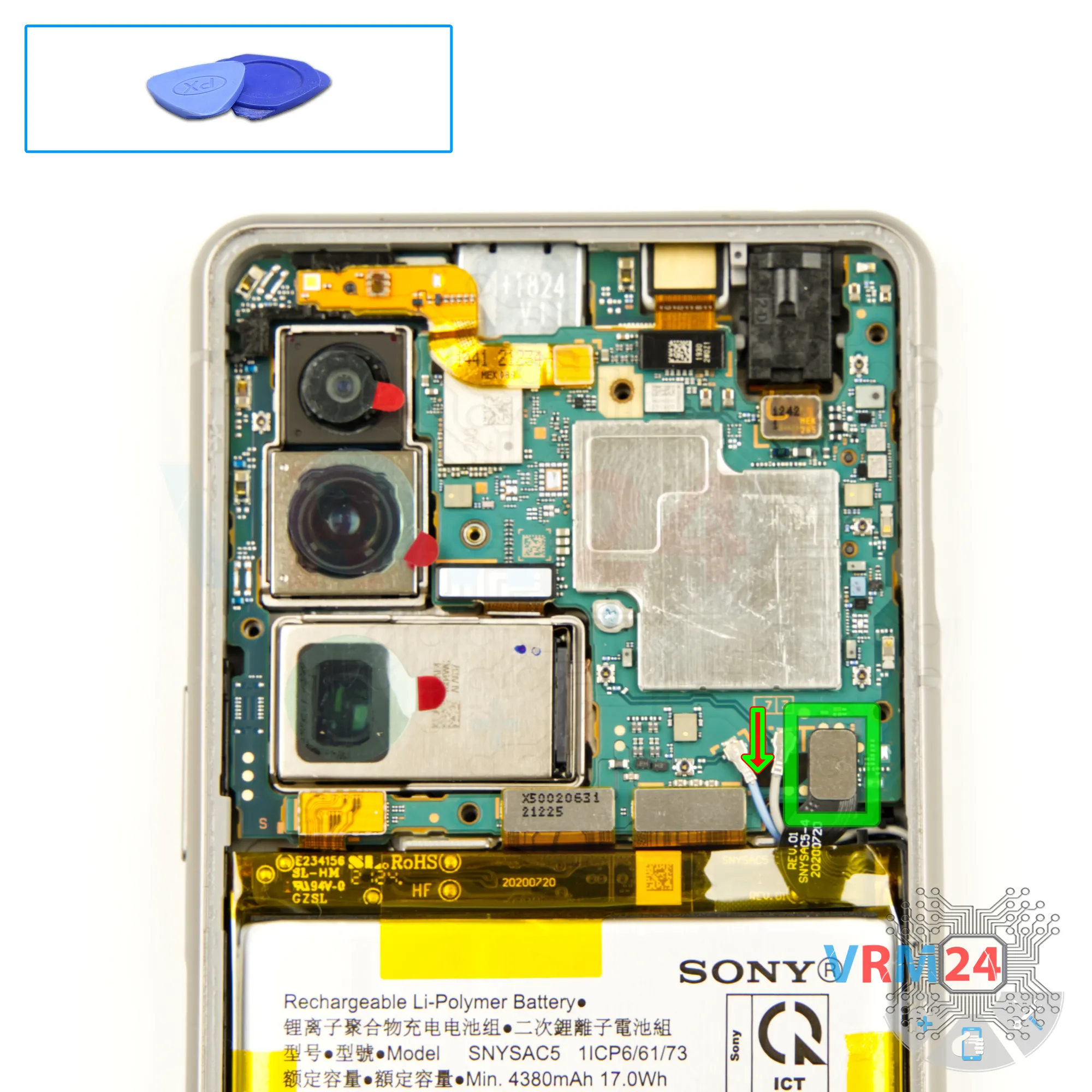
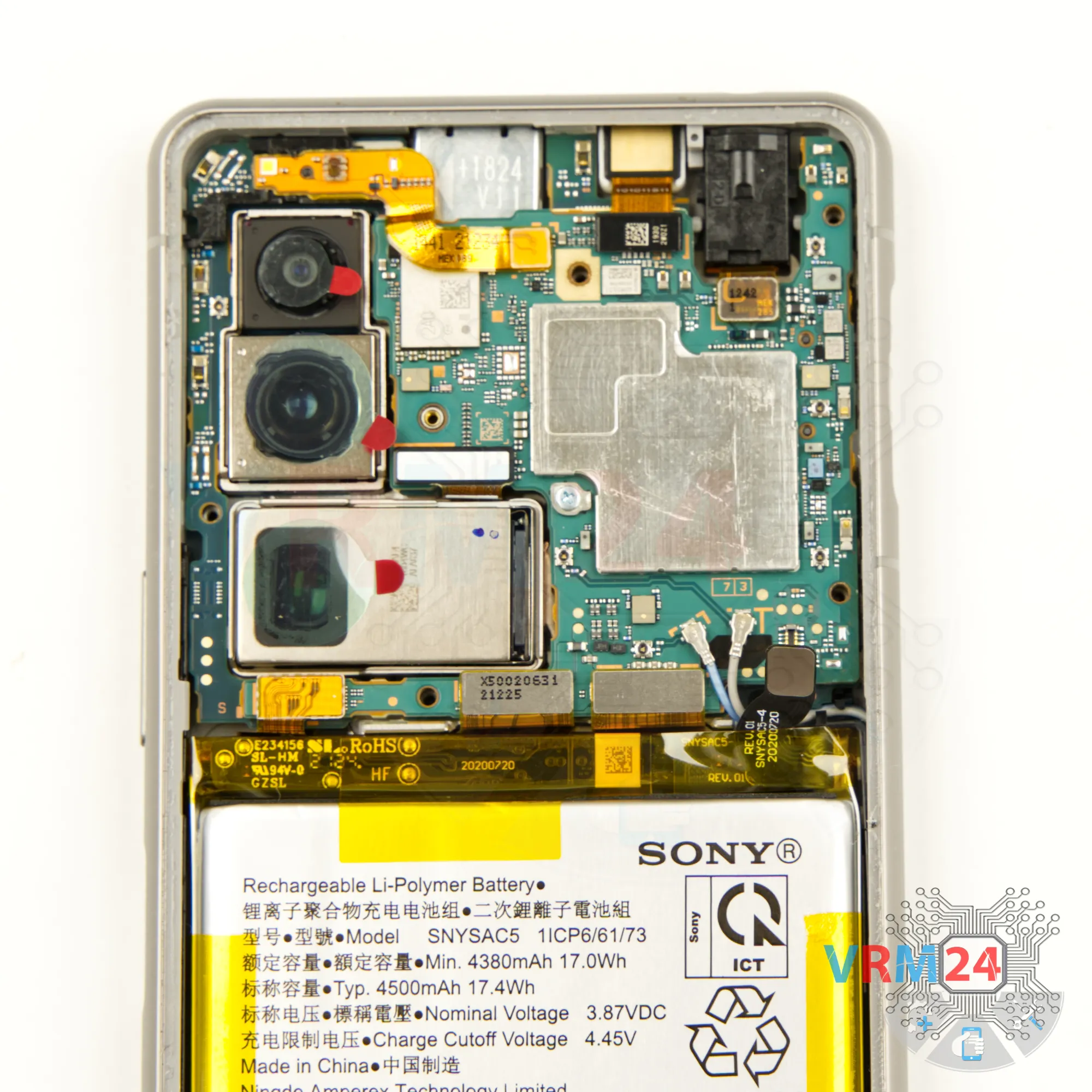
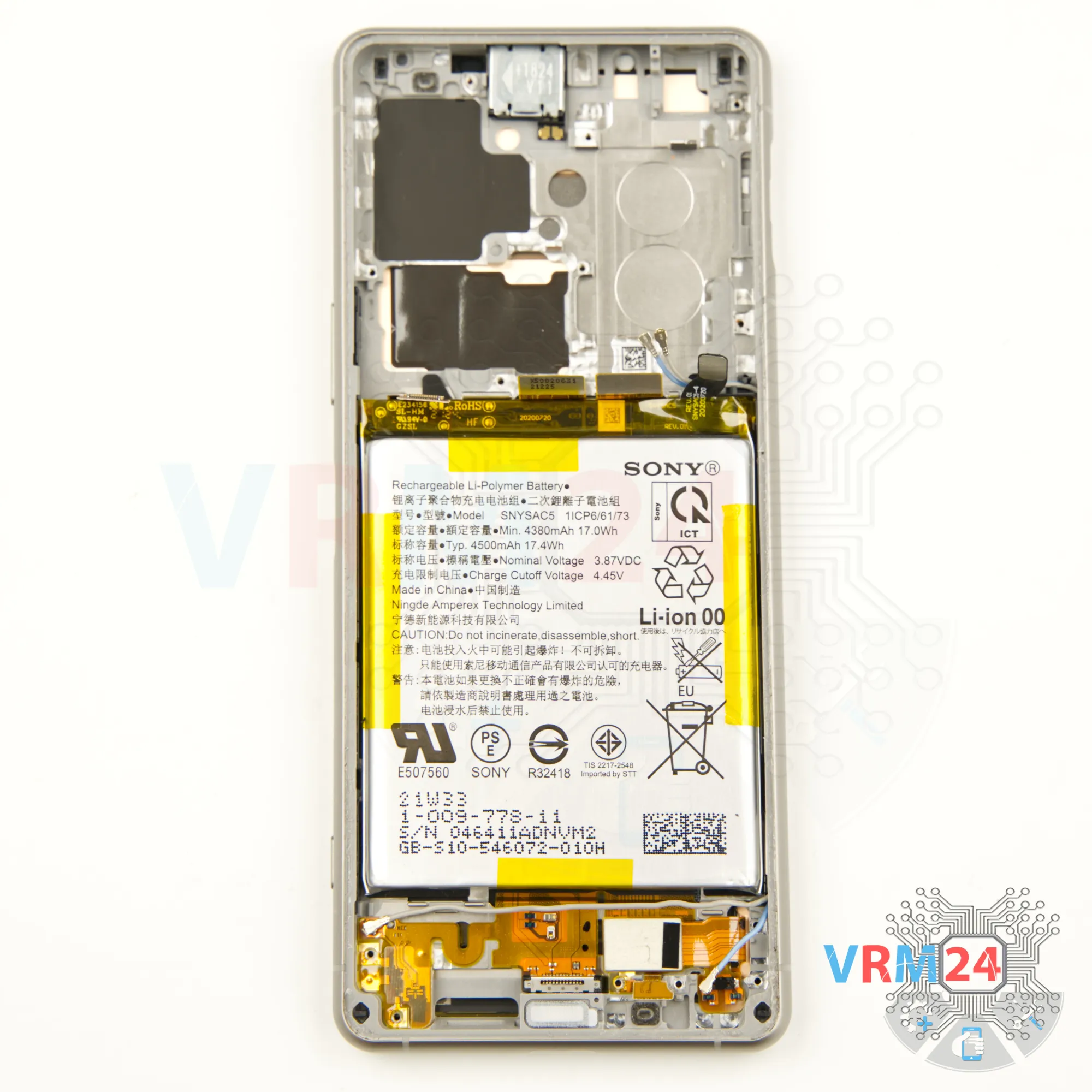
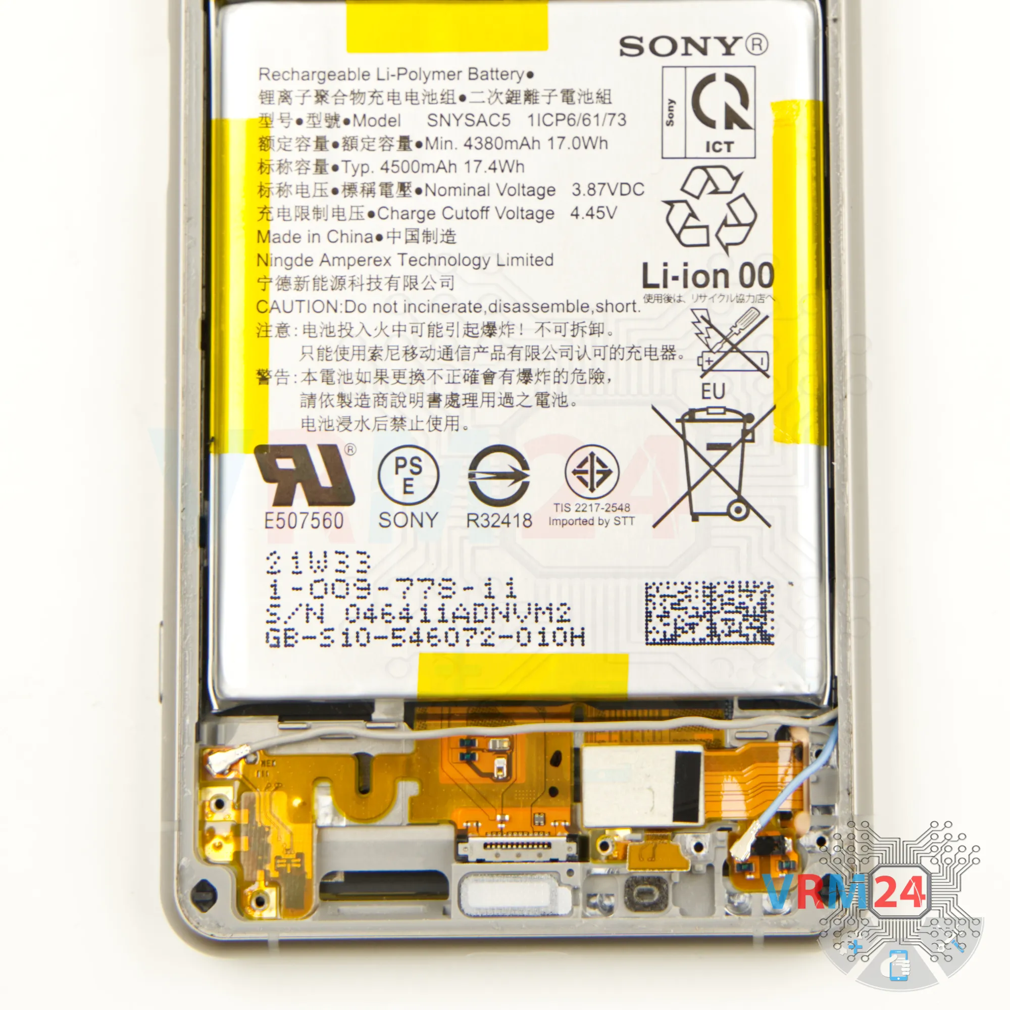
Step 7. Disconnect the battery connector
Next, we disconnect the battery connector using a non-metallic tool .
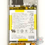
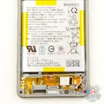
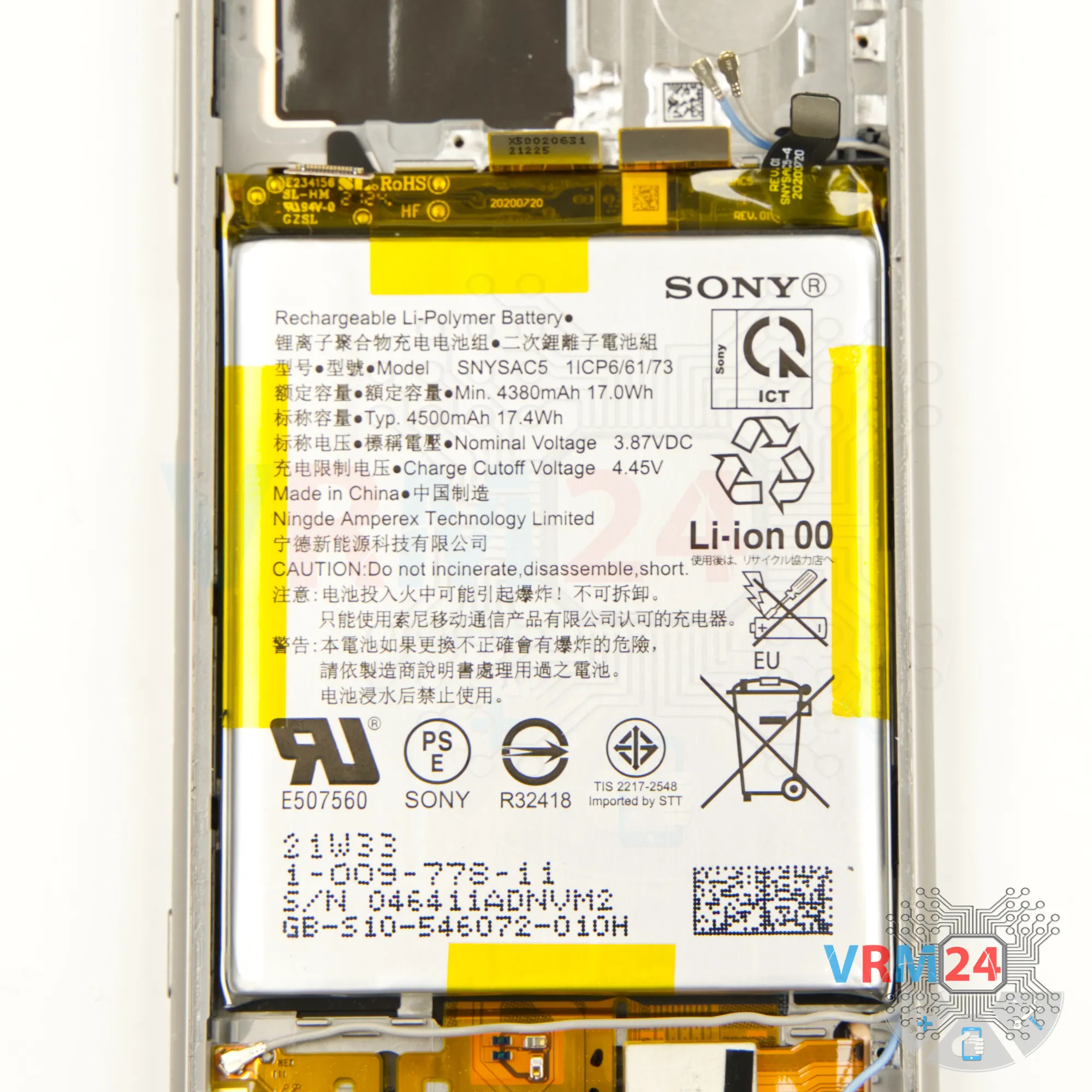
Sony Xperia 5 III has SNYSAC5 battery model with 4500mAh capacity.
Gently lift and unhook the connector, making sure to handle it with care.


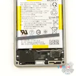
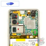
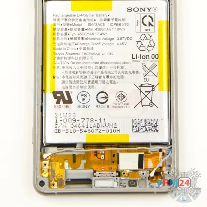
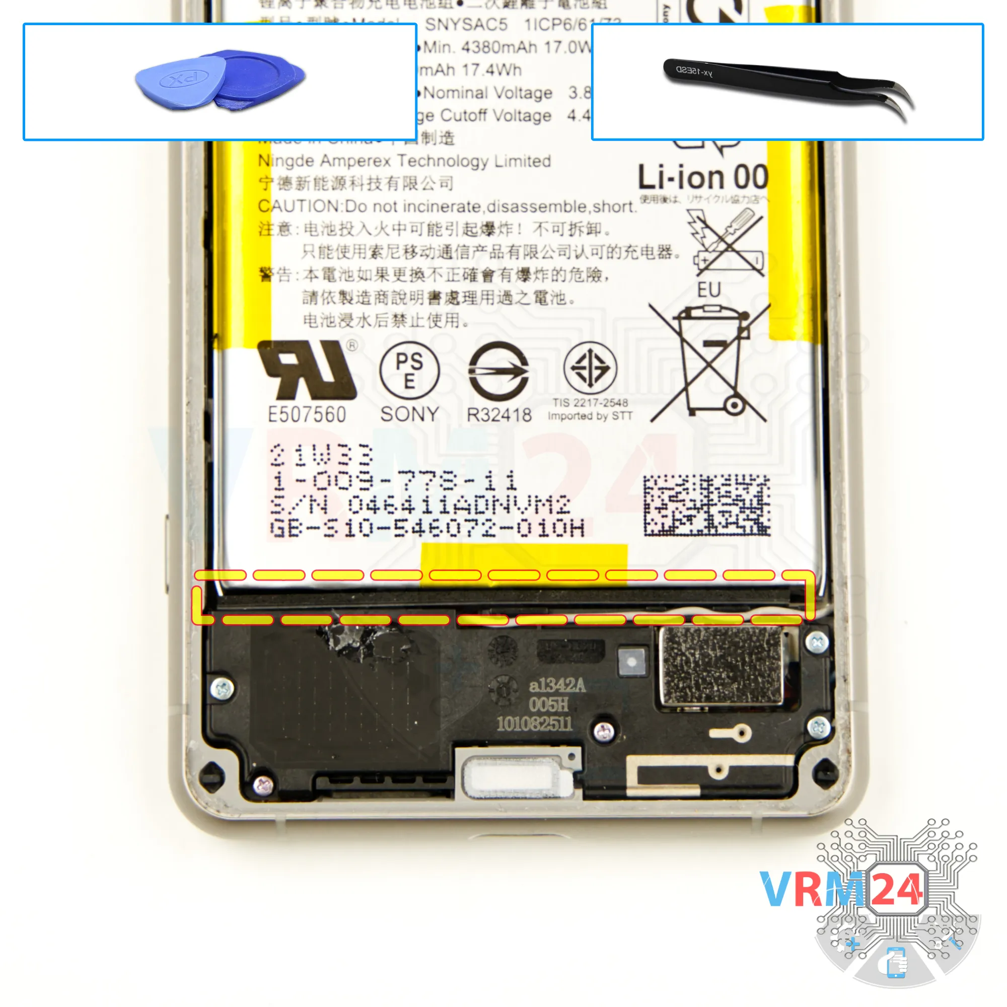
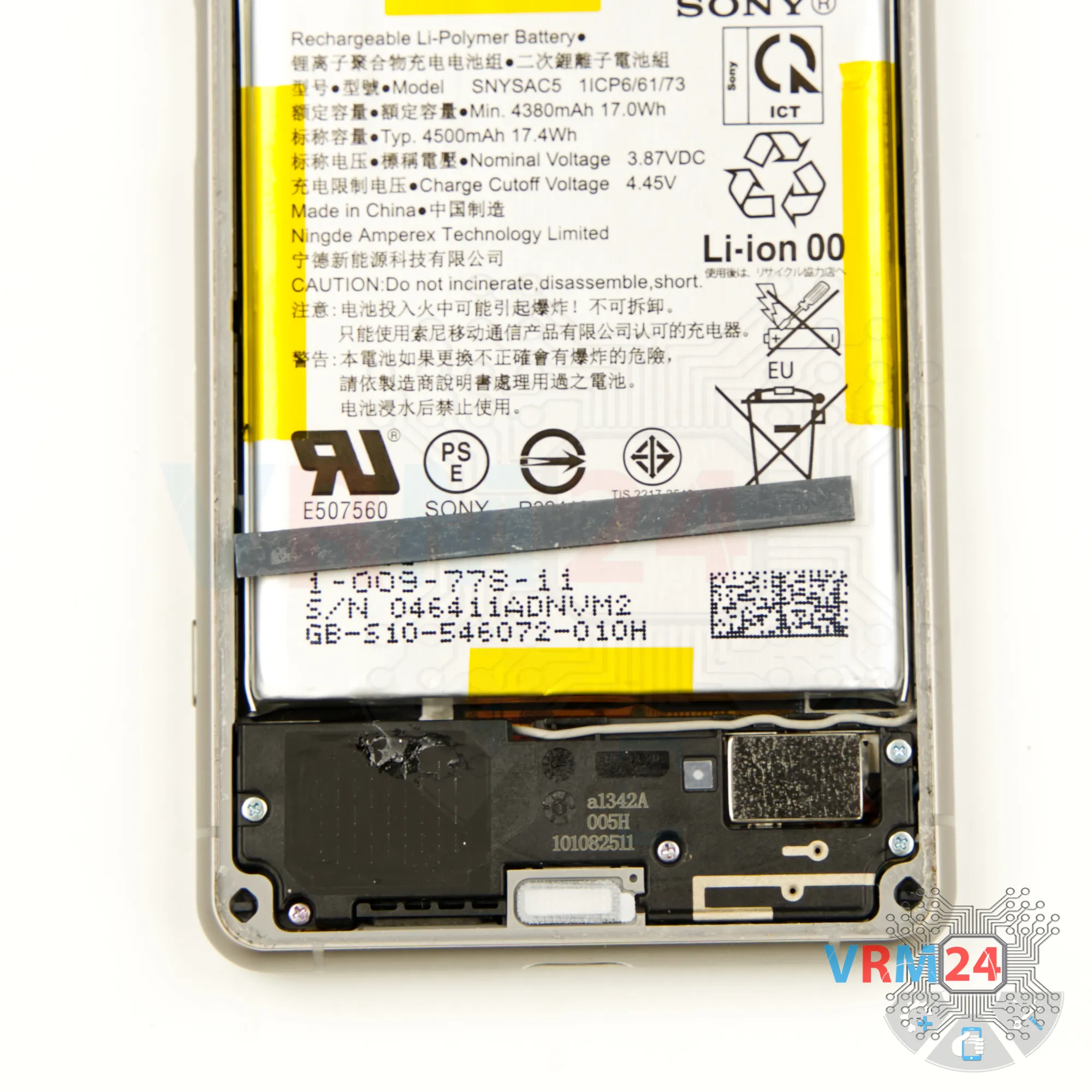
Step 8. Remove the small gasket
We need to take out the gasket at the bottom to make sure it doesn't get in the way.
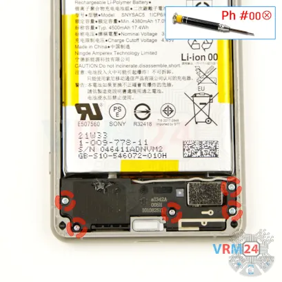
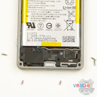
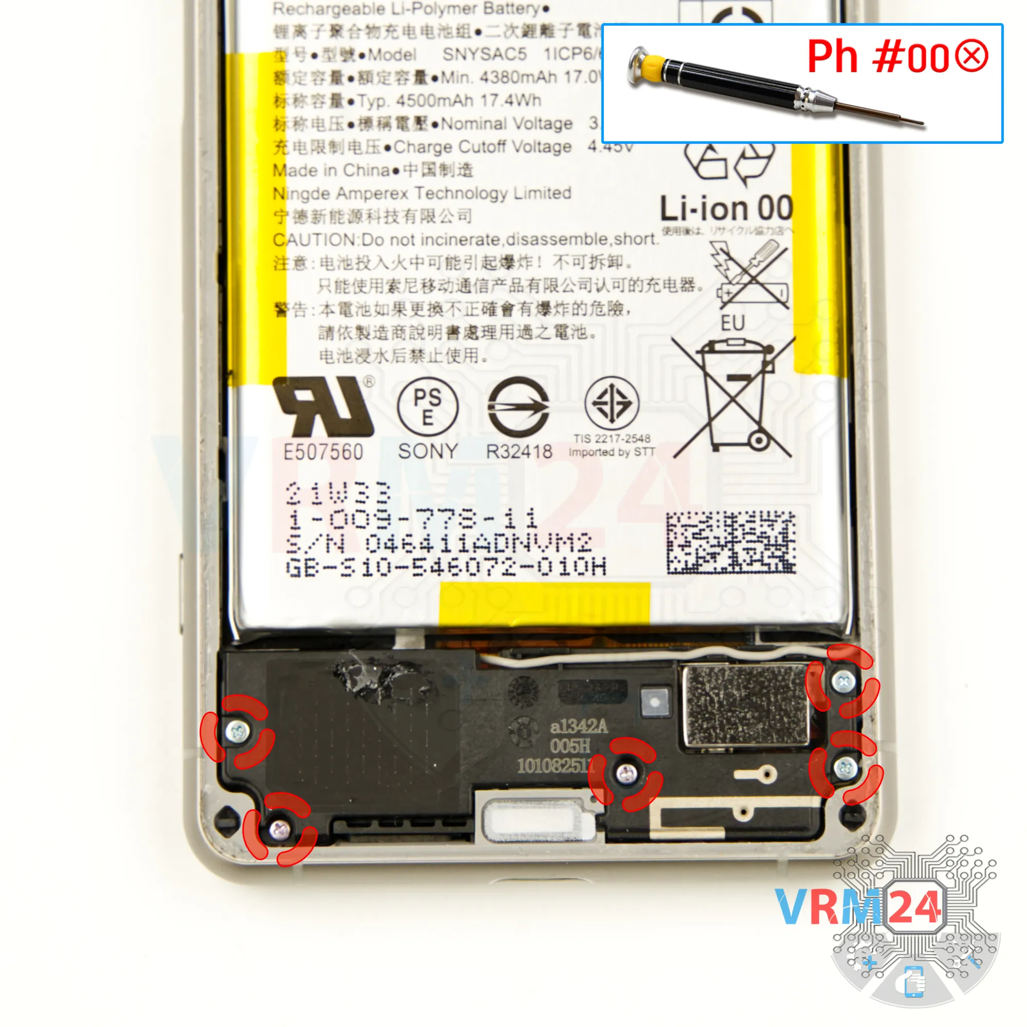
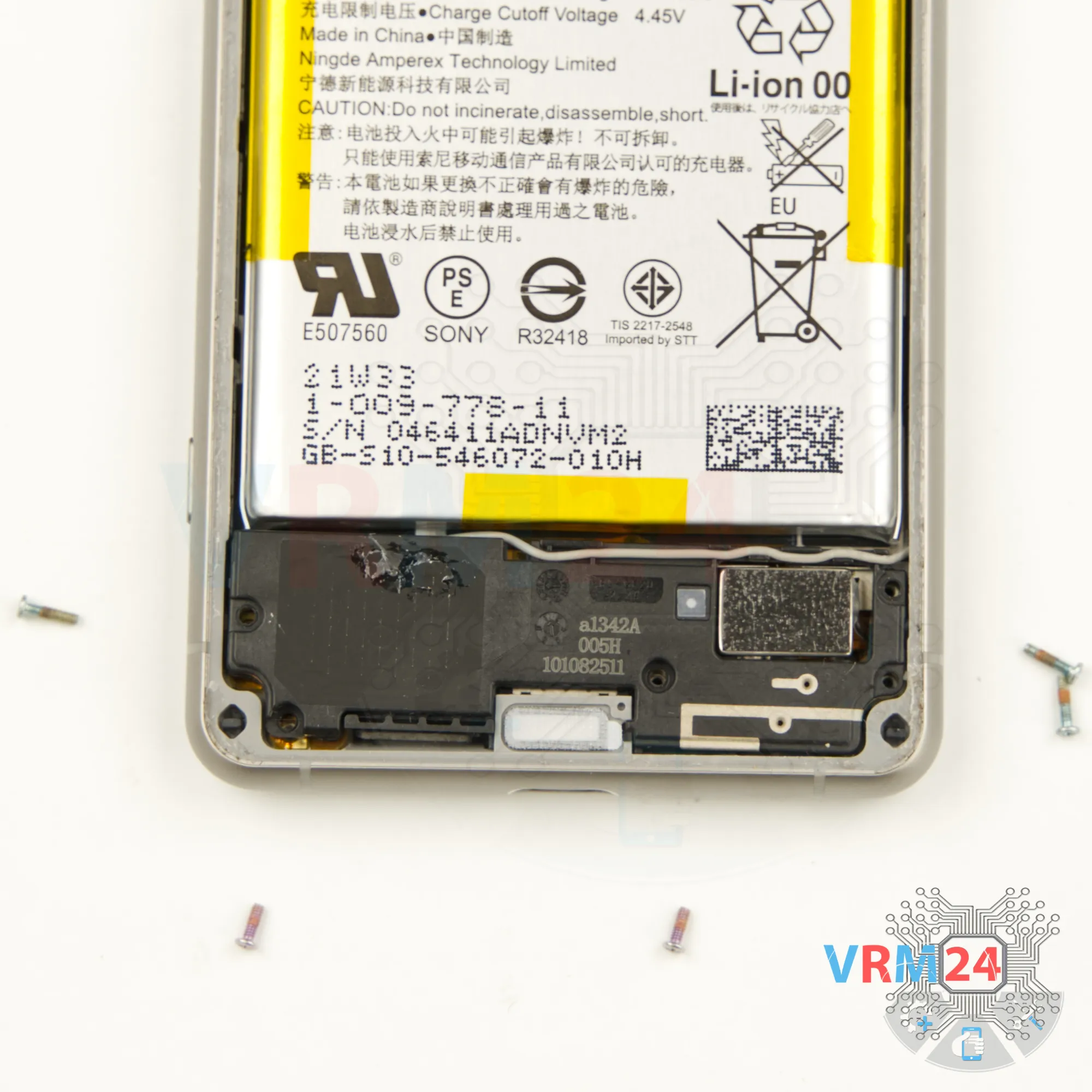
Step 9. Unscrew the screws
Next, move on to unscrewing the five screws at the bottom. Use a 1.5mm Phillips screwdriver or a Phillips #000 for this.
Keep in mind that the screws at the bottom are different—the ones at the very bottom are smaller and shorter.
⚠️️ If any screws get stuck, you can use tweezers to help remove them.
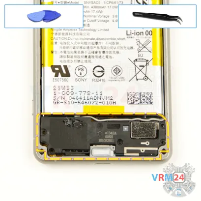

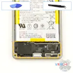
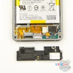
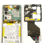
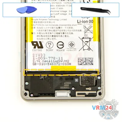
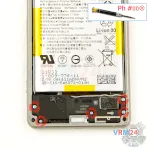
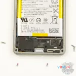
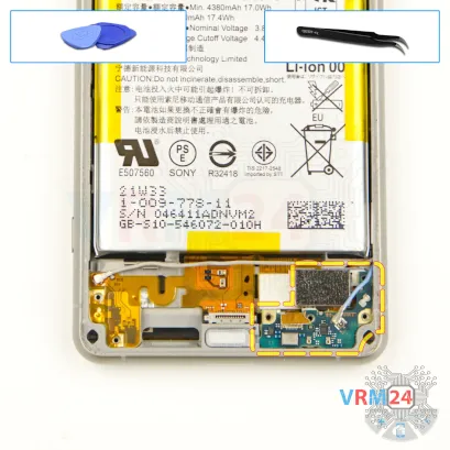
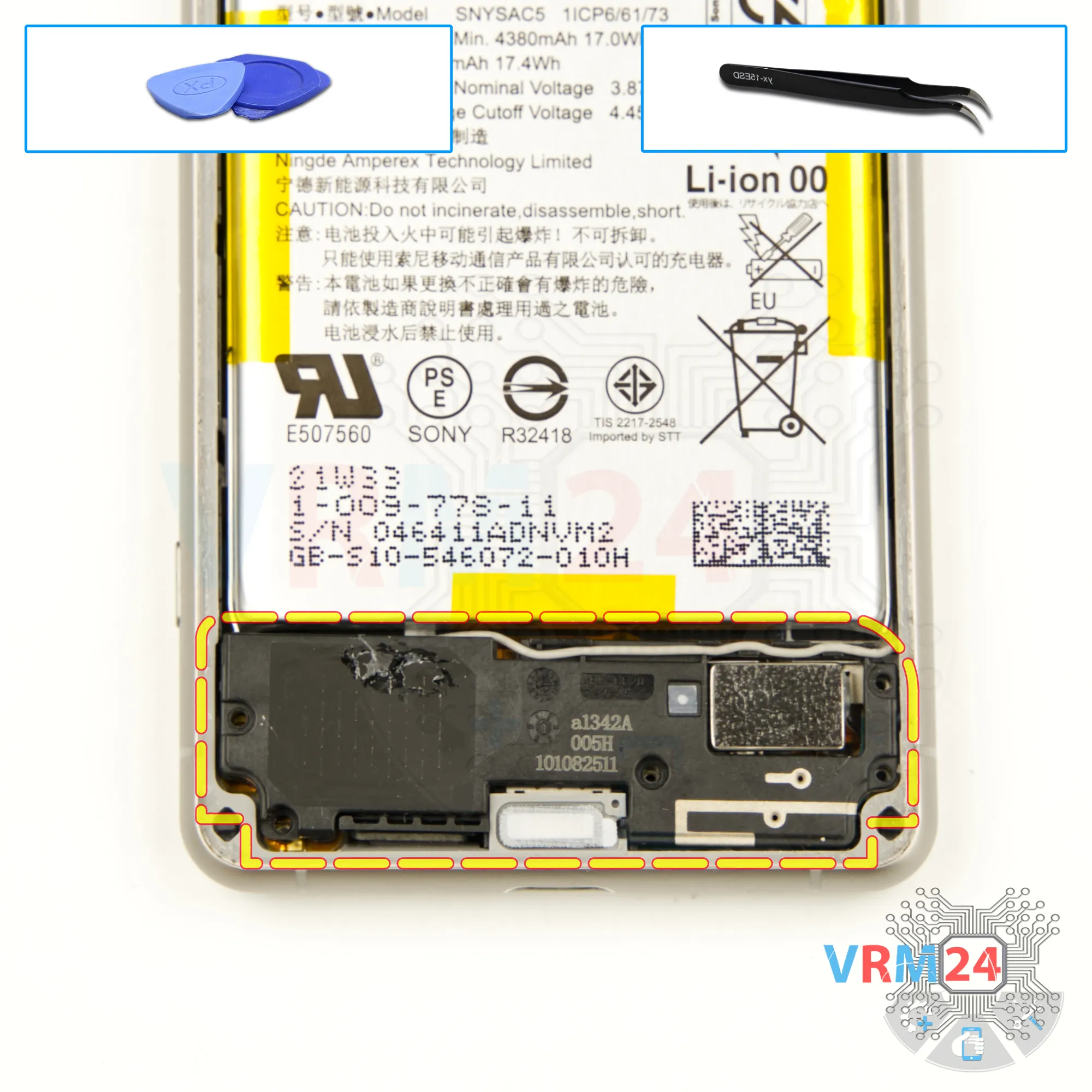
Step 10. Remove the loudspeaker
After removing the screws, the next step is to detach the cover with the speaker.
Carefully lift the edge to remove it.
Keep in mind that the cover contains a coaxial cable, so you'll need to gently disconnect the coaxial cable connector or free the cable where it's secured to the cover.
⚠️️ Be cautious while handling the cable to avoid any accidental damage.
Once the cover is detached, set it aside.

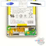

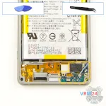
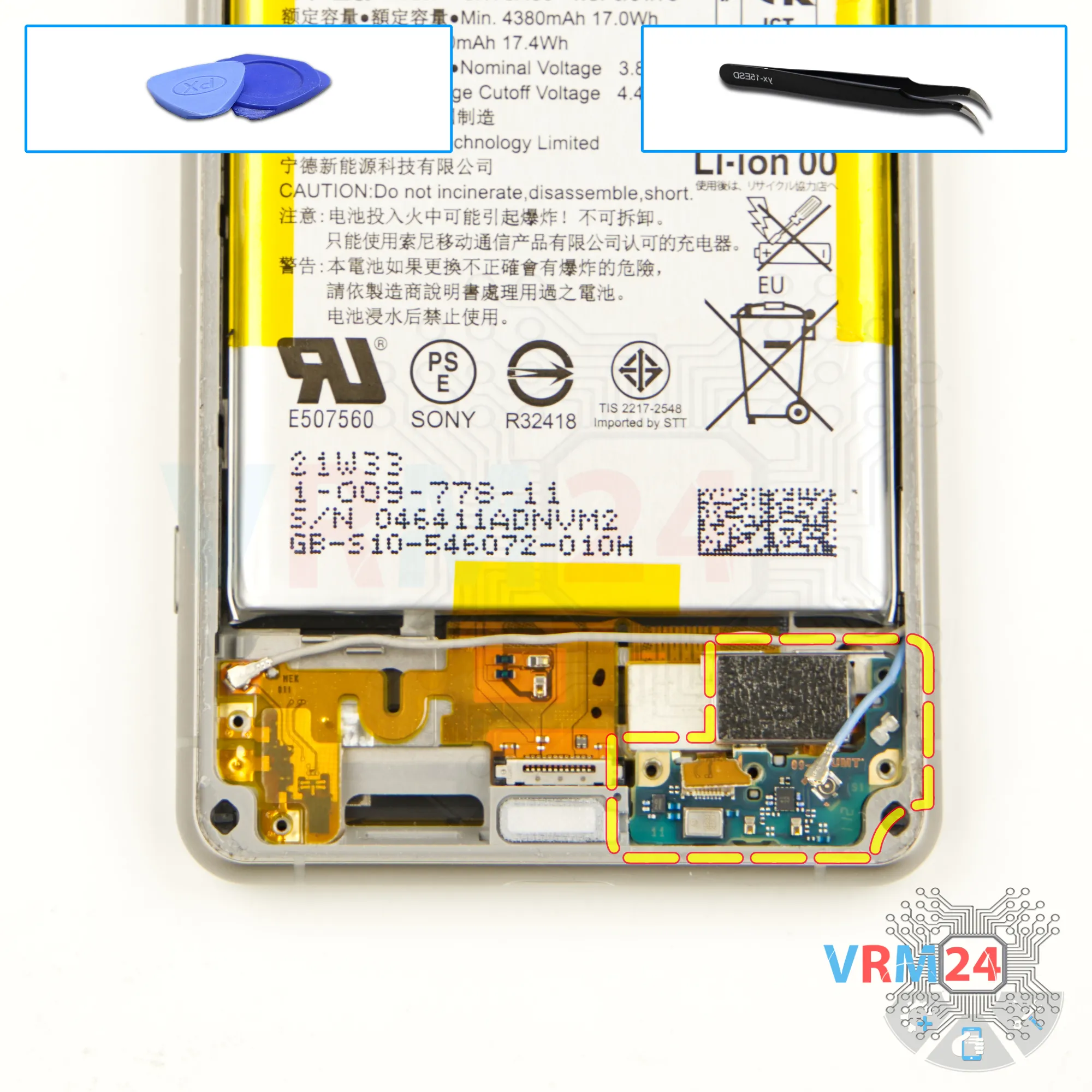
Step 11. Disconnect the connectors
Now we can disconnect the connectors. We disconnect two connectors of two coaxial cables and one inter-board cable connector.
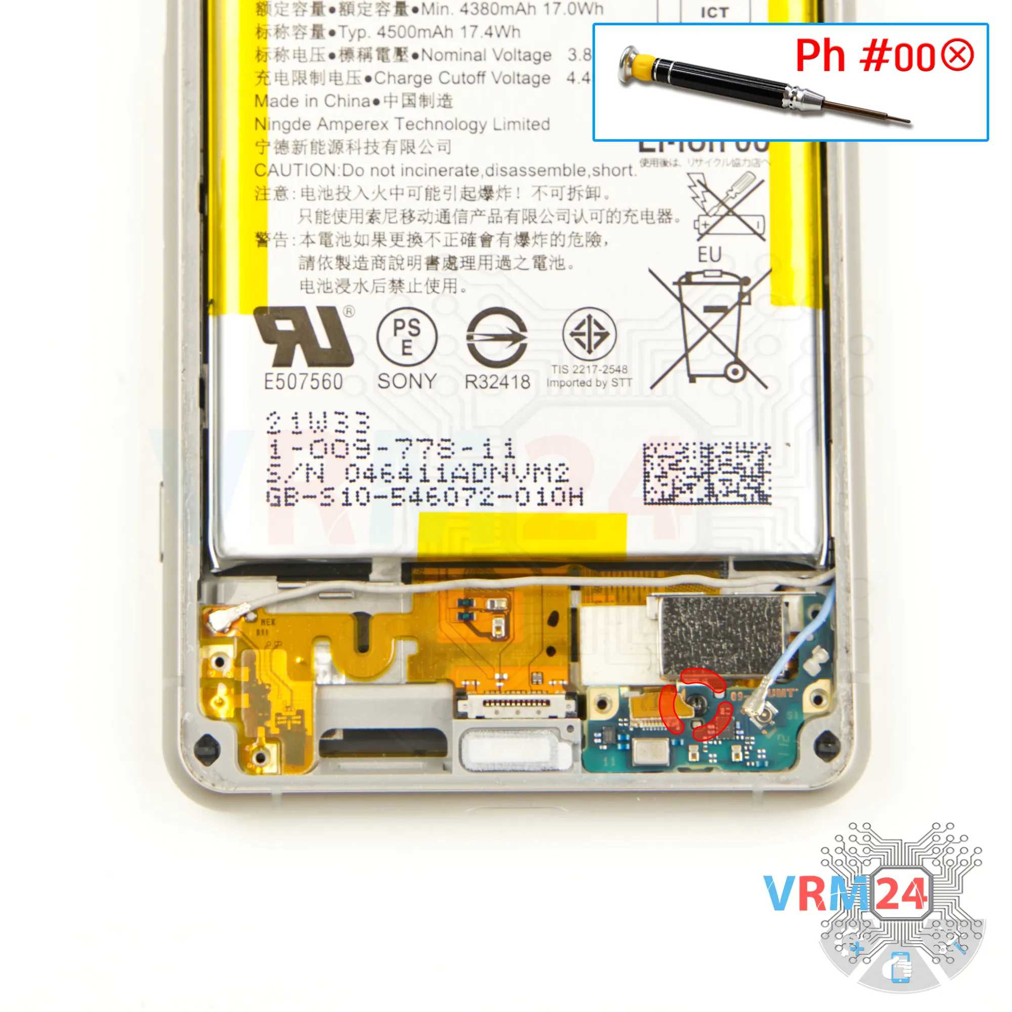
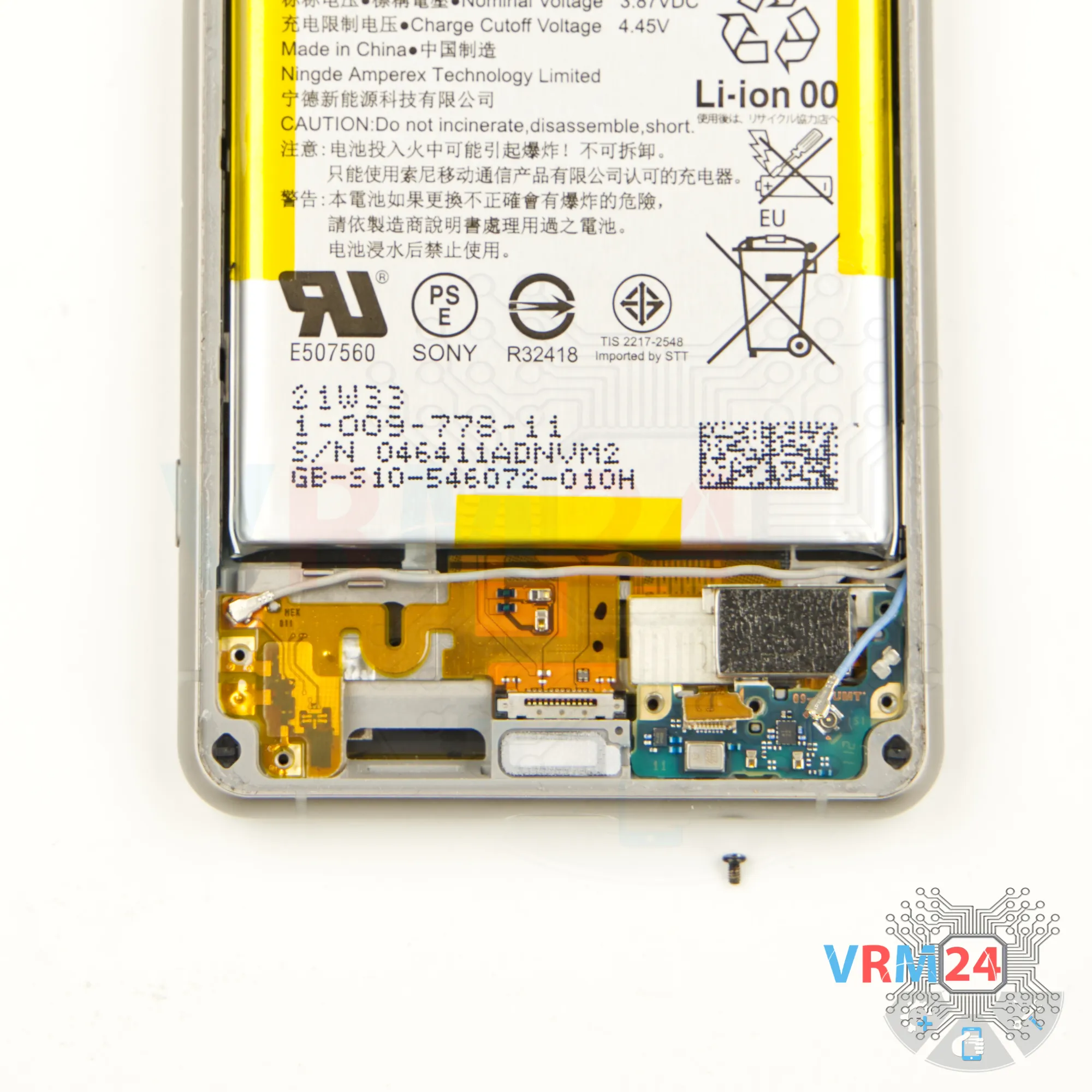
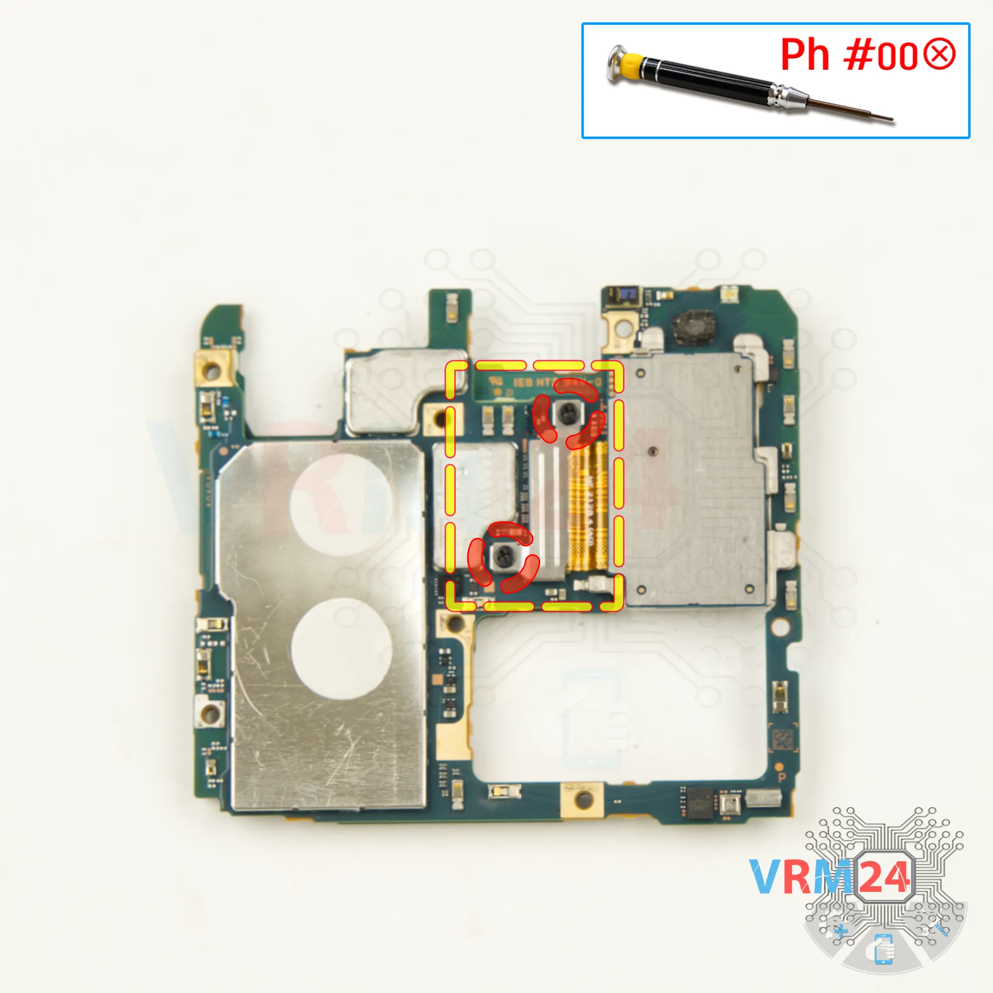
Step 12. Unscrew one screw
We also need to remove one screw that secures the sub-board. We use Phillips #000 screwdriver.
⚠️️ Since most screws are different, it is better to place them on a special surface, separate from the previous ones.


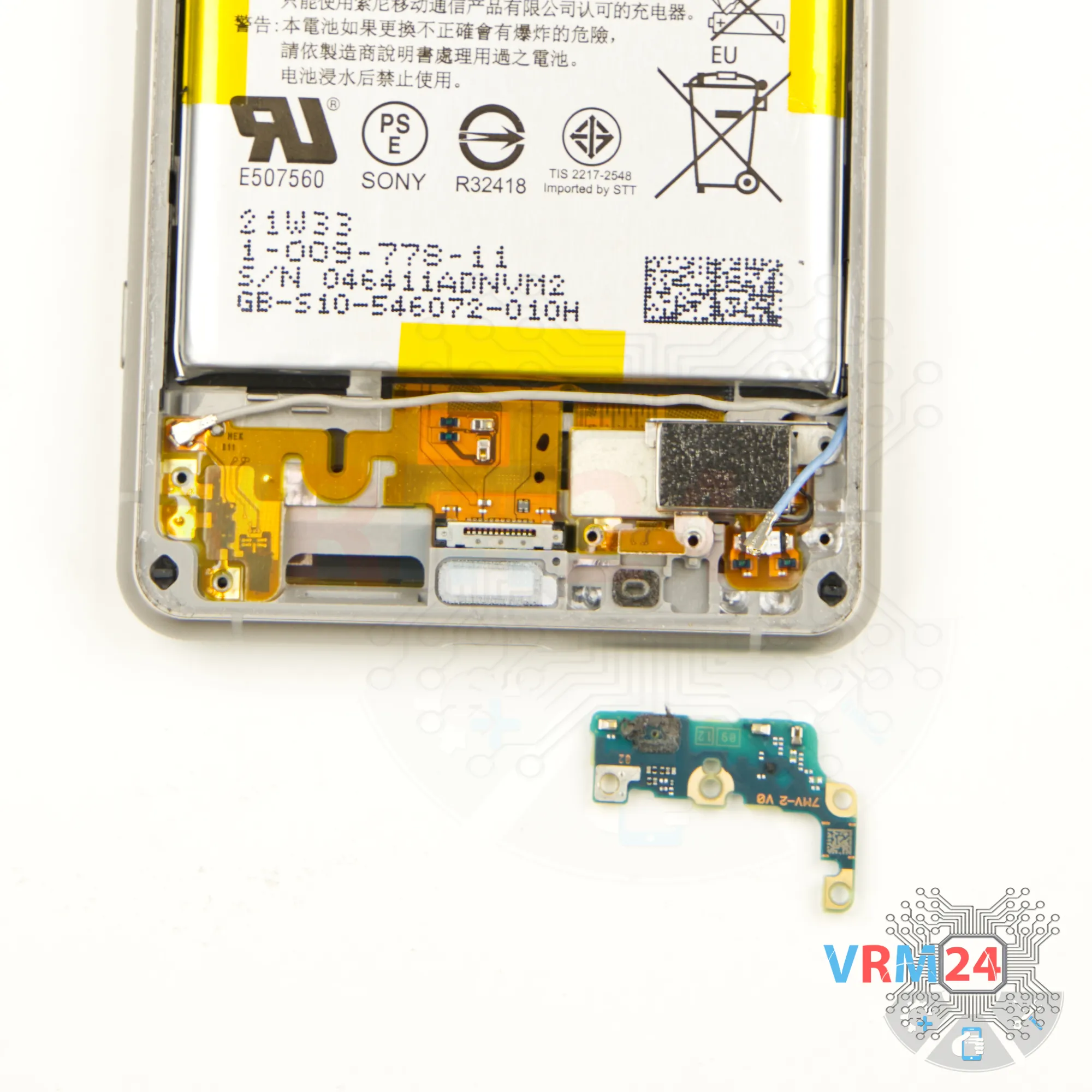
Step 13. Remove the sub-board
And we can detach this circuit board.
Gently pry it off. The sub-board is glued near the microphone. Gently pull it out.
Also please note that this model has a separate charging port. We remove the sub-board and put it aside. We can see that the sub-board was glued in the area of the microphone. This is most likely a waterproofing feature.

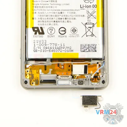
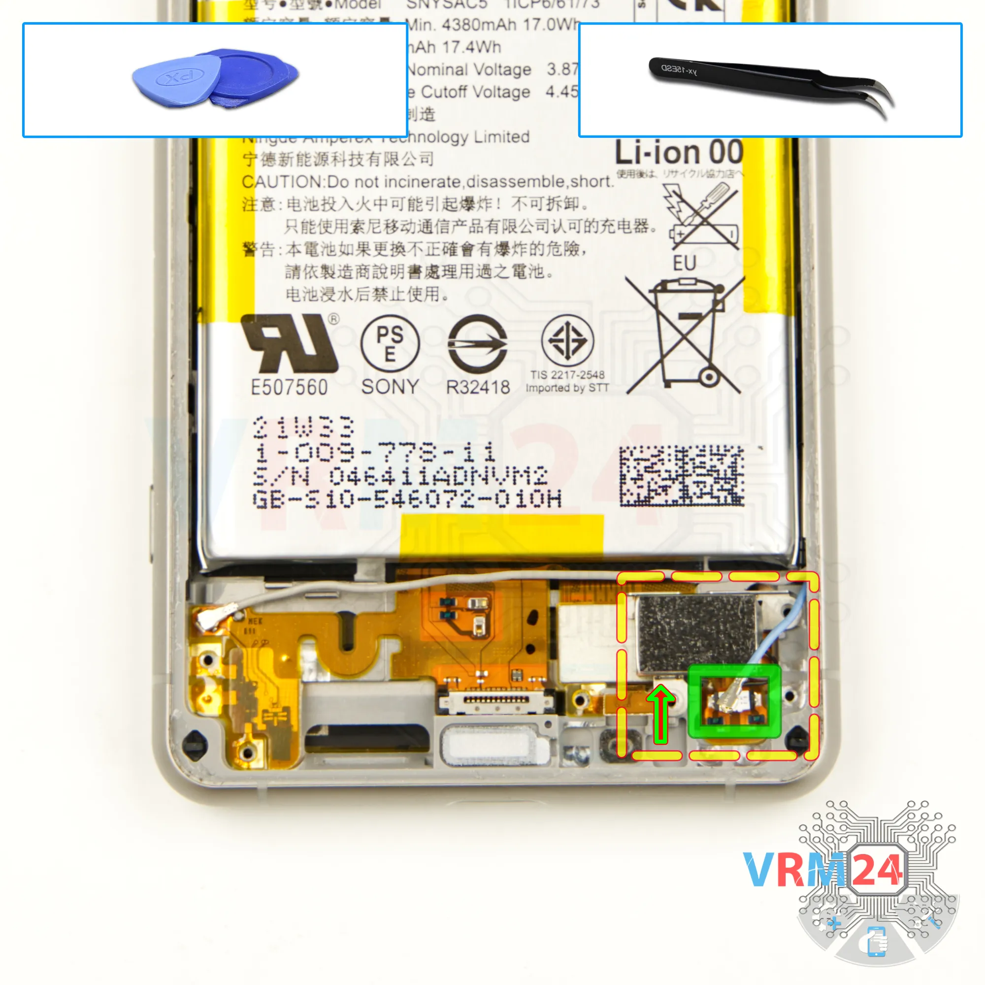
Step 14. Remove the vibration motor
We can disconnect the connector and remove the vibration motor after that. We hook it up and remove the vibration motor to the side.

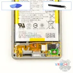
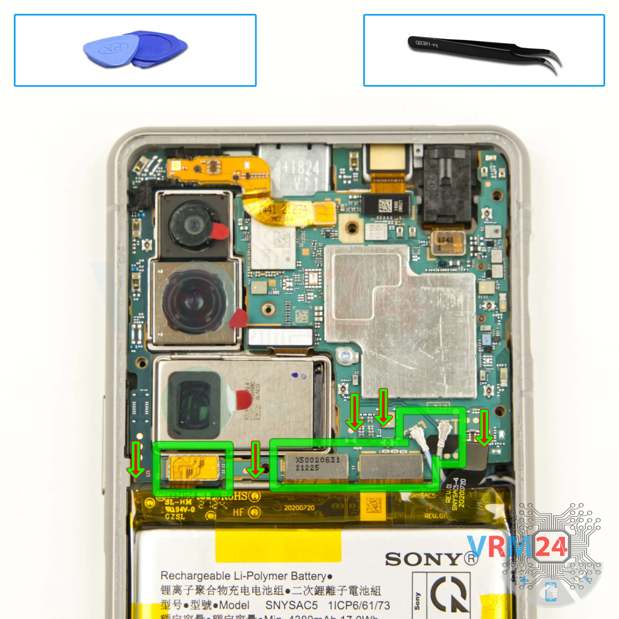
Step 15. Disconnect the connectors
Disconnect the inter-board cable connector, the display cable connector, and the charging port connector. Then, carefully disconnect the two coaxial cable connectors.

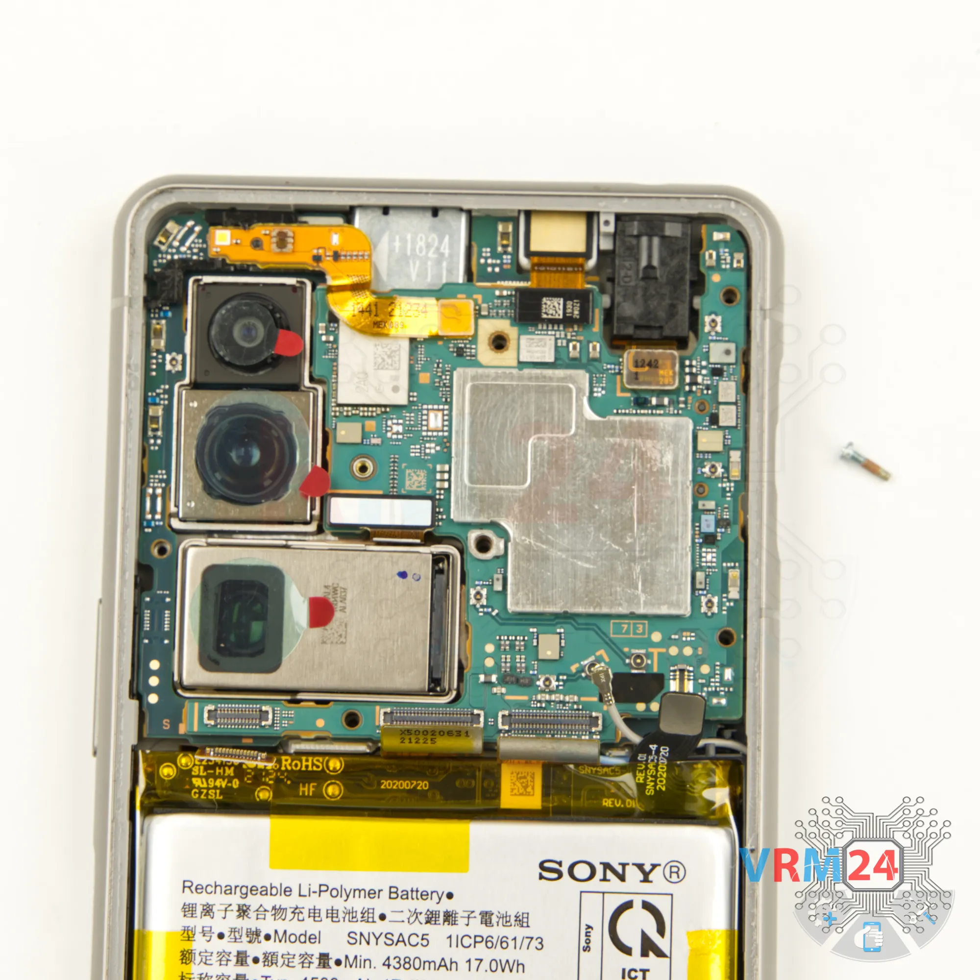
Step 16. Unscrew one screw
We also need to remove one screw that secures the motherboard. For this we also use a 1.5mm Phillips screwdriver.
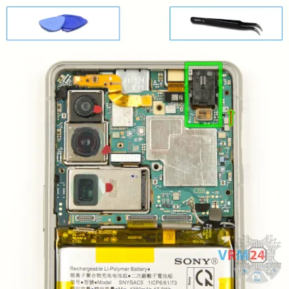


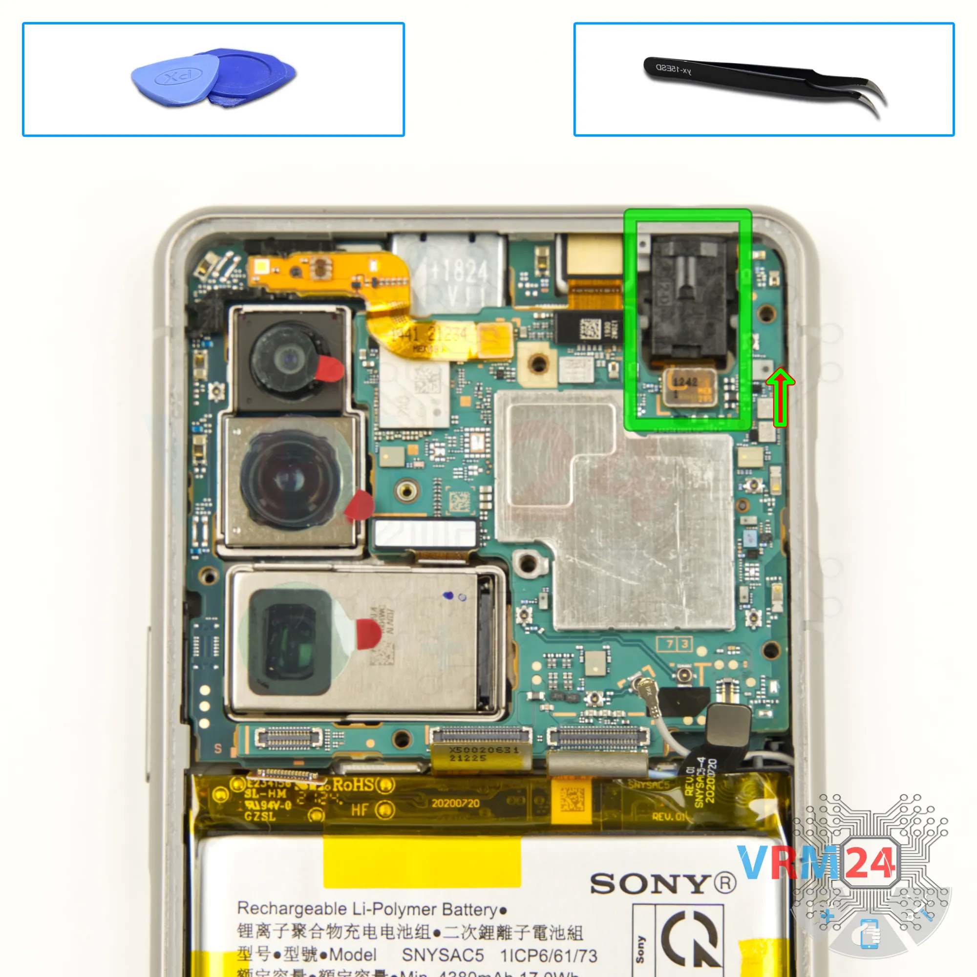
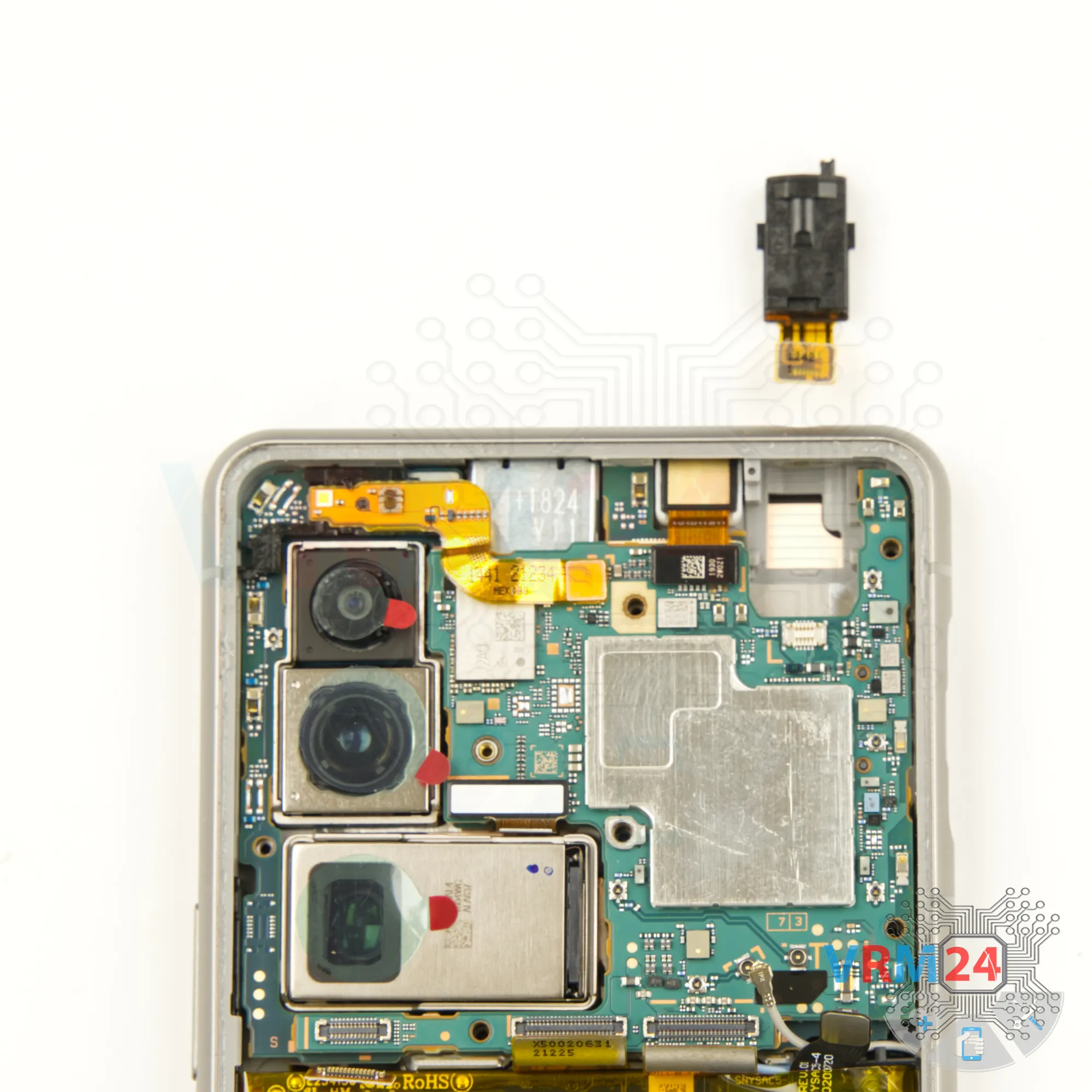
Step 17. Remove the headphone port
After that, we disconnect the connector and remove the headset jack port. We carefully remove the port, putting it aside.

Step 19. Remove the proximity sensor
Then we disconnect the connector of the sensor cable. We remove the cable.


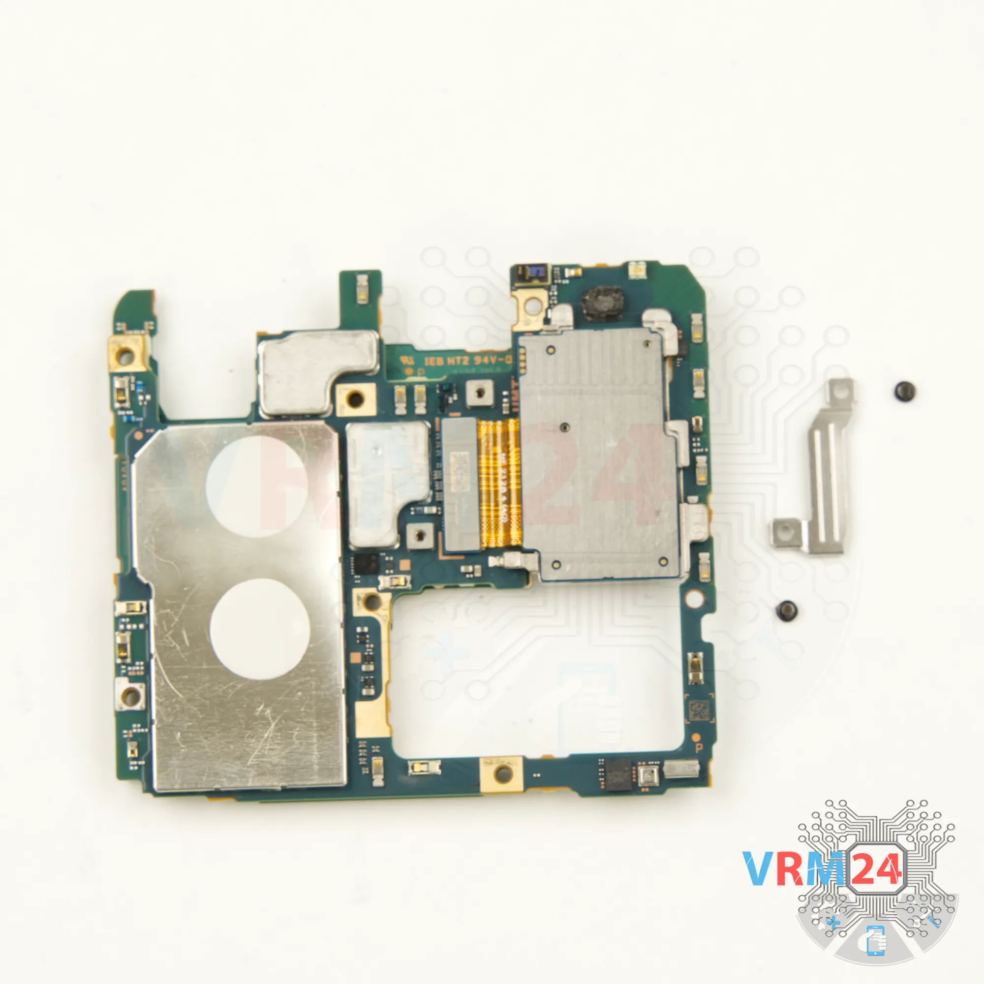
Step 20. Remove the bracket
We need to unscrew one screw that secures the motherboard at the top. For this we also use a 1.5mm Phillips screwdriver. We remove the bracket too.


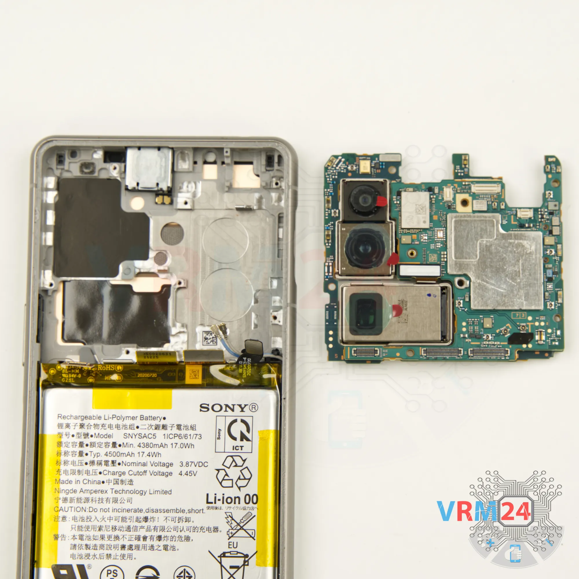
Step 21. Remove the motherboard
After that we can detach the motherboard.
We bend the cables to the side so that they are out of our way. Find the right place where the motherboard is attached. Gently lift it up. See that nothing is in our way.
We don't have to pull the circuit board by force.


Step 22. In the display frame remained
ℹ️️ In the display frame remained: the earpiece speaker, battery, and cables.
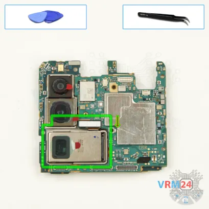
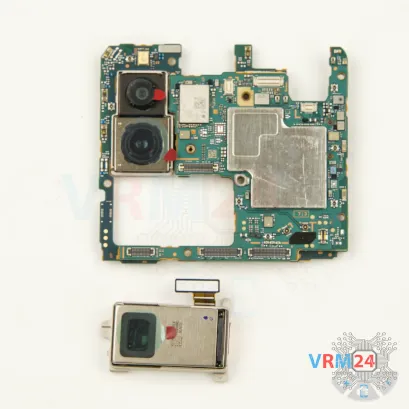


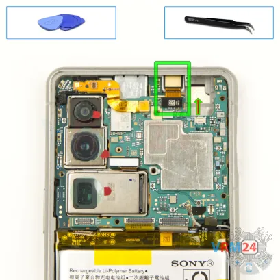
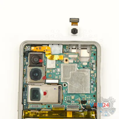
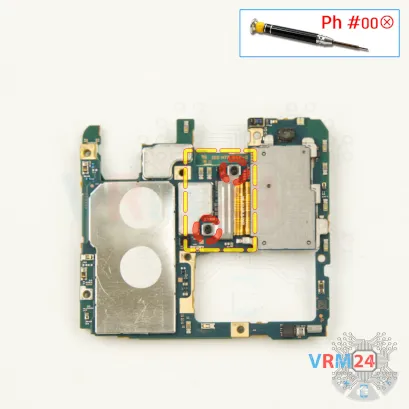
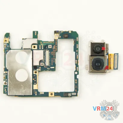
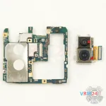
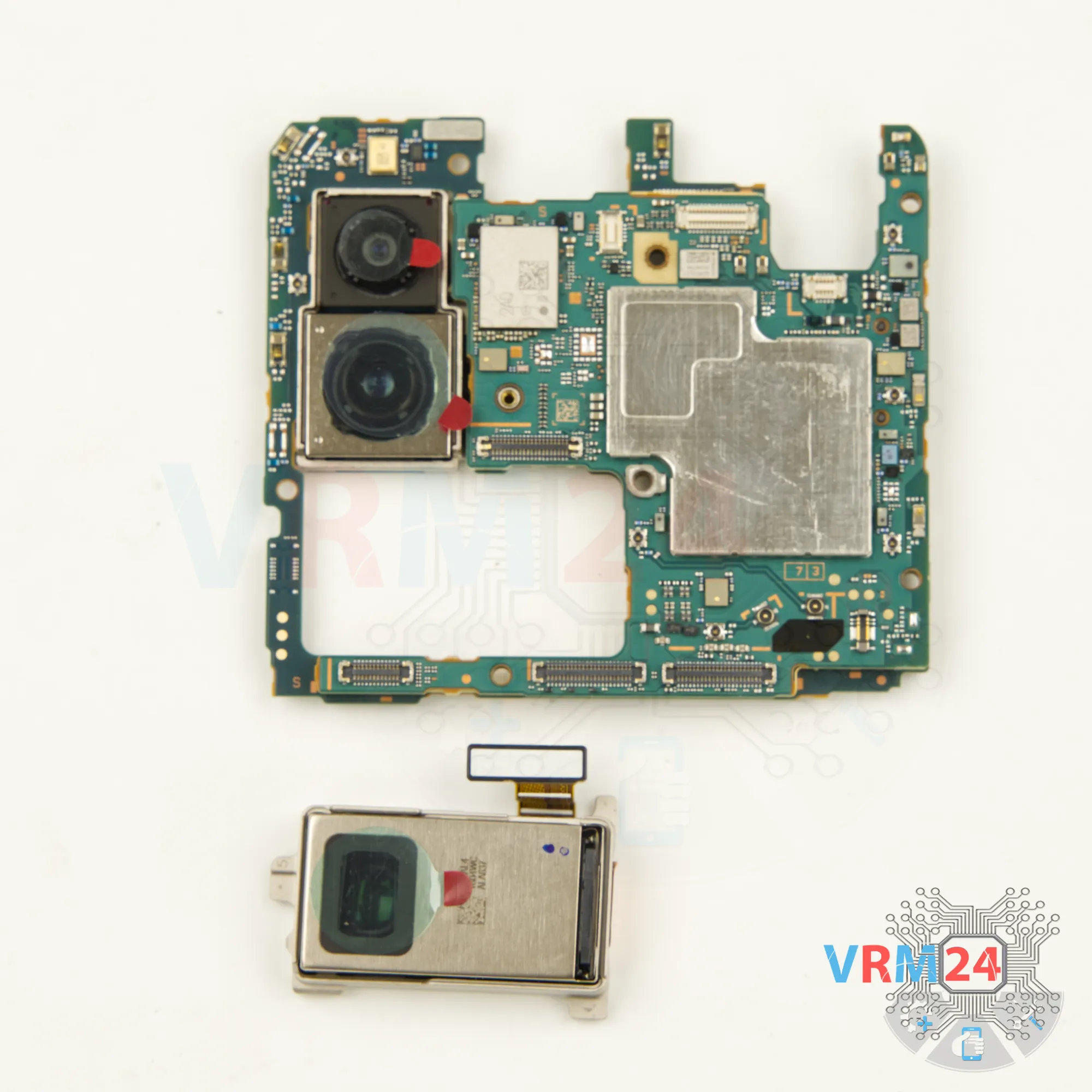
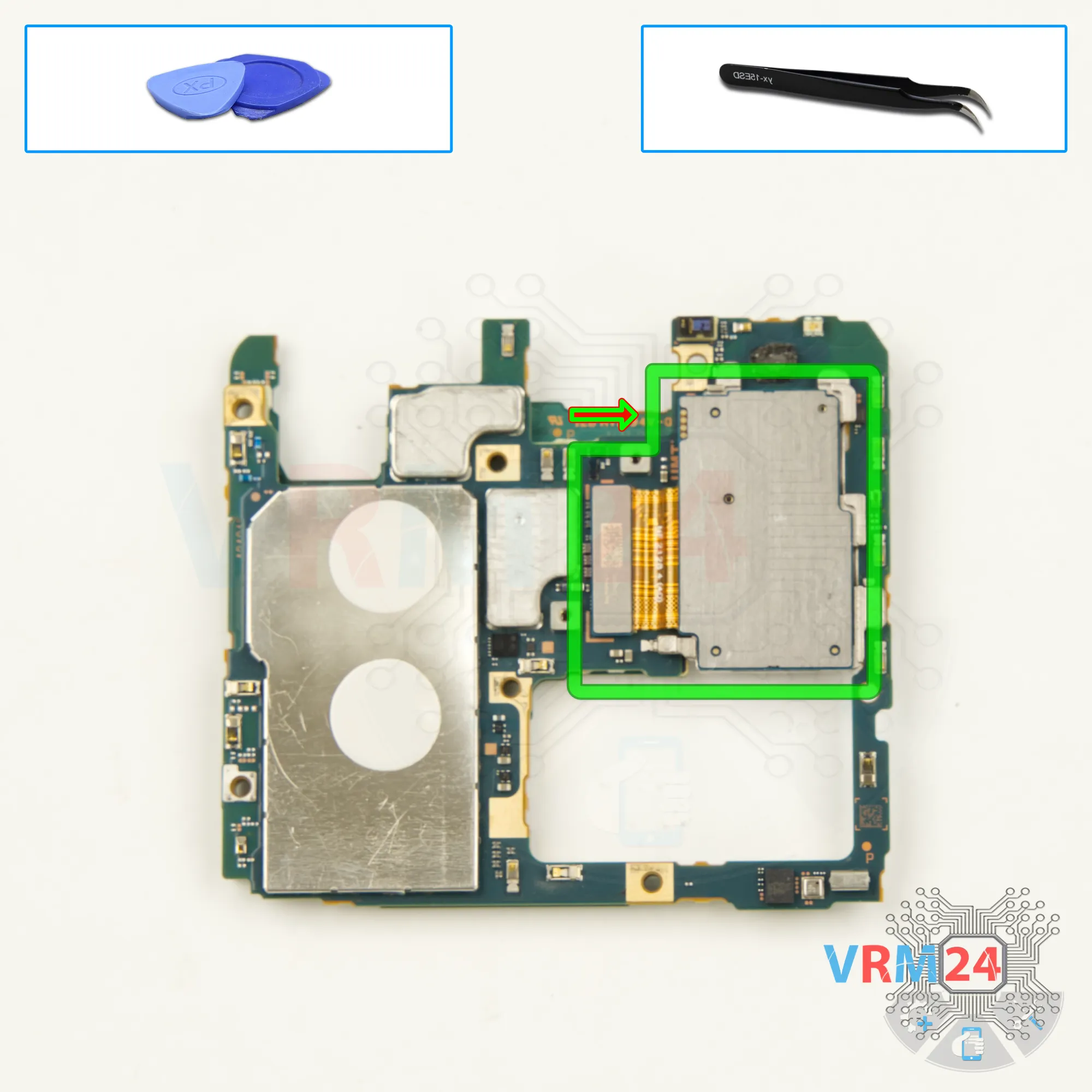
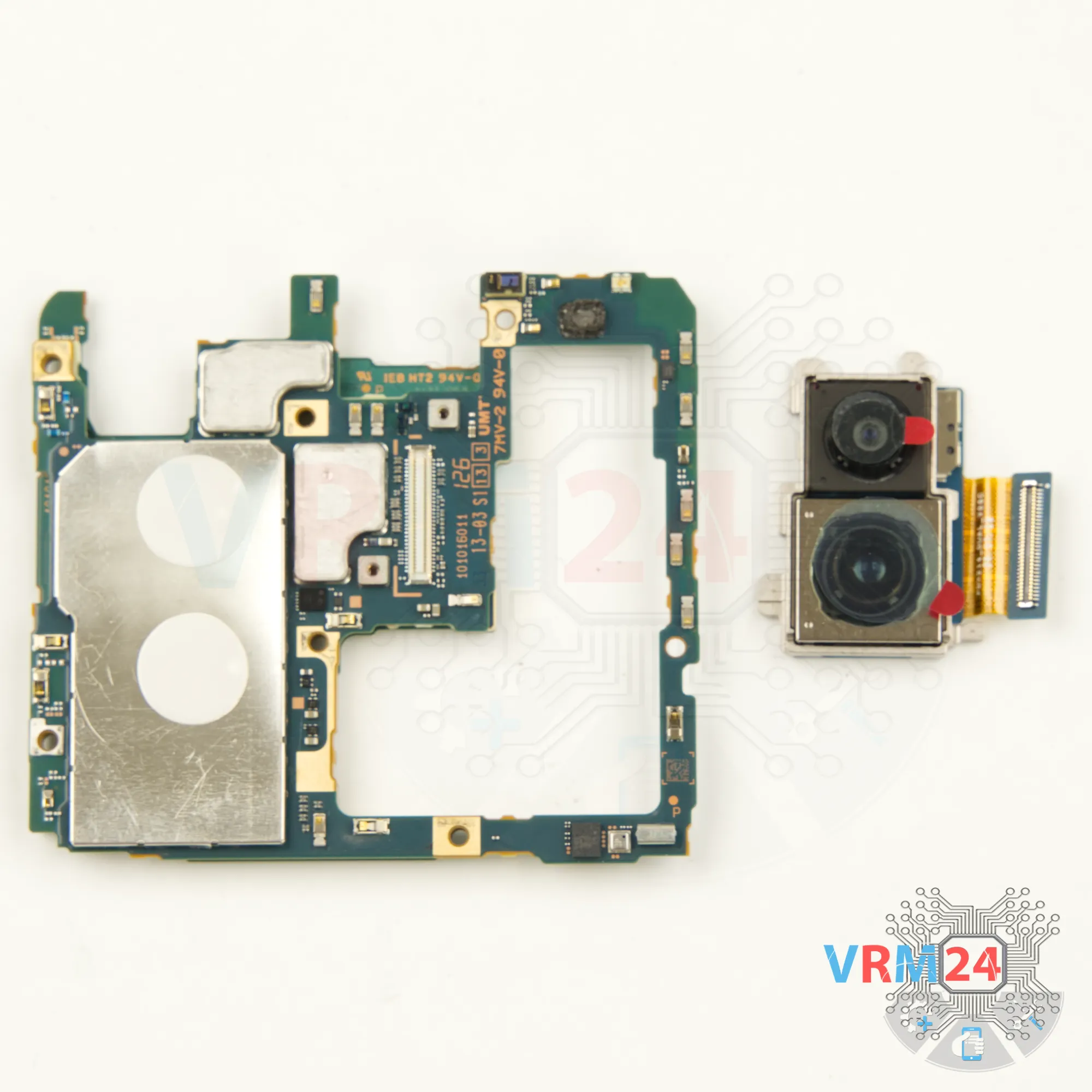
Step 23. Remove the rear camera
Now we need to disconnect the big camera. Disconnect the connector and take out the camera.

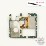

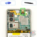
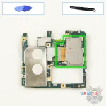
Step 24. Unscrew the screws
Using a 1.5 mm Phillips screwdriver, unscrew the two screws and disconnect the connector bracket.

Detailed disassembly instructions of Sony Xperia 5 III in the video, made by our mobile repair & service center:
If you have a question, ask us, and we will try to answer in as much detail as possible. If this article was helpful for you, please rate it.

Disassembling\Repair has medium complexity and takes about minutes in time.
Our manual is suitable for all models Sony Xperia 5 III — Sony Xperia 5 III XQ BQ62/G released for markets in different countries.
Back to the list