
⚠️️ Before disassembling, do not forget to turn your phone off.
Teardown difficulty:
Moderate
Moderate
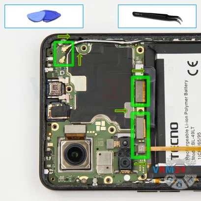
Recommended tools


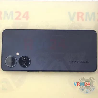
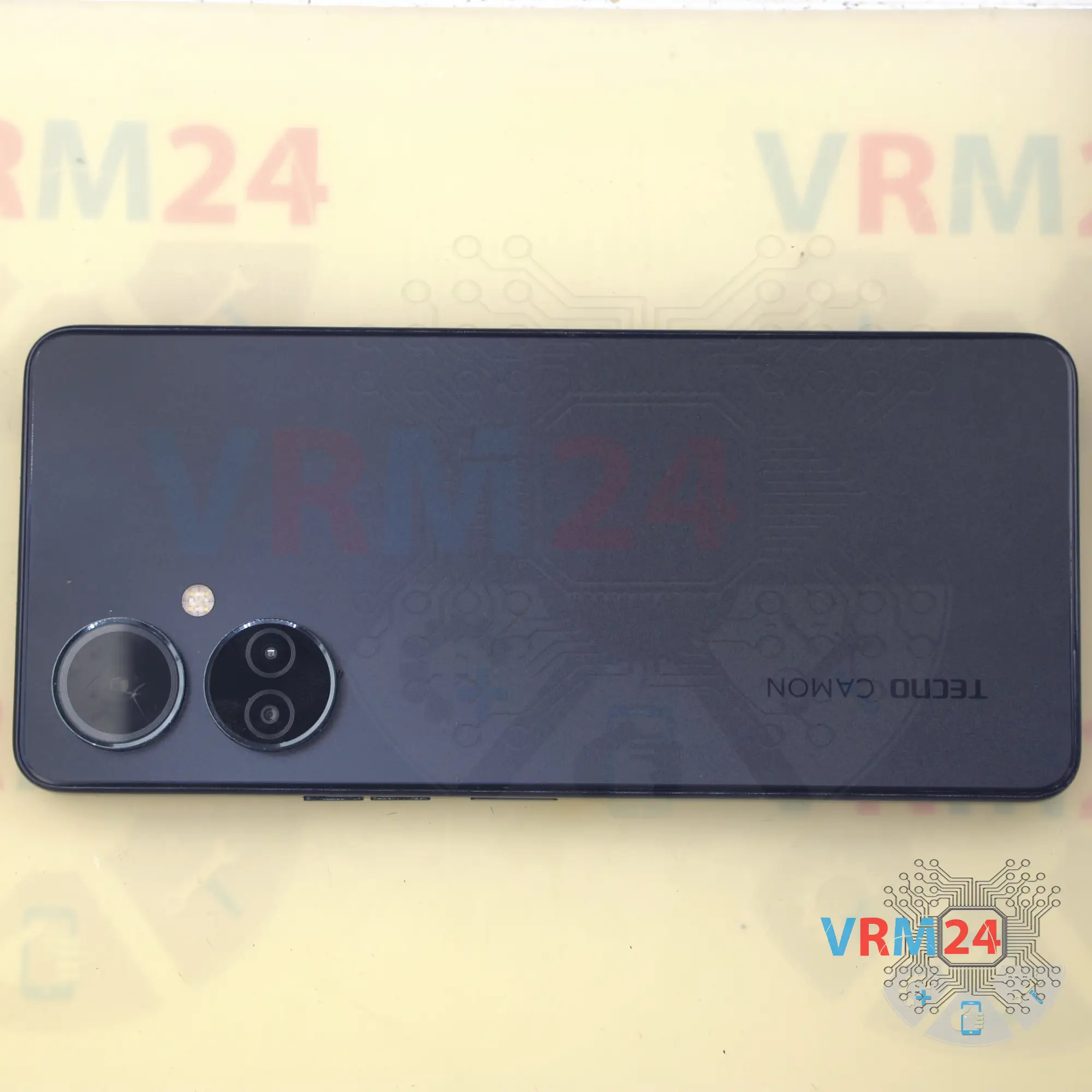
Disassembly/Repair of the mobile device Tecno Camon 19 with each step description and the required set of tools.


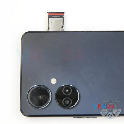
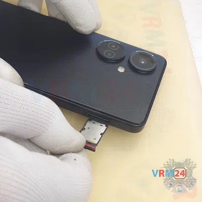

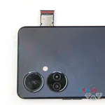


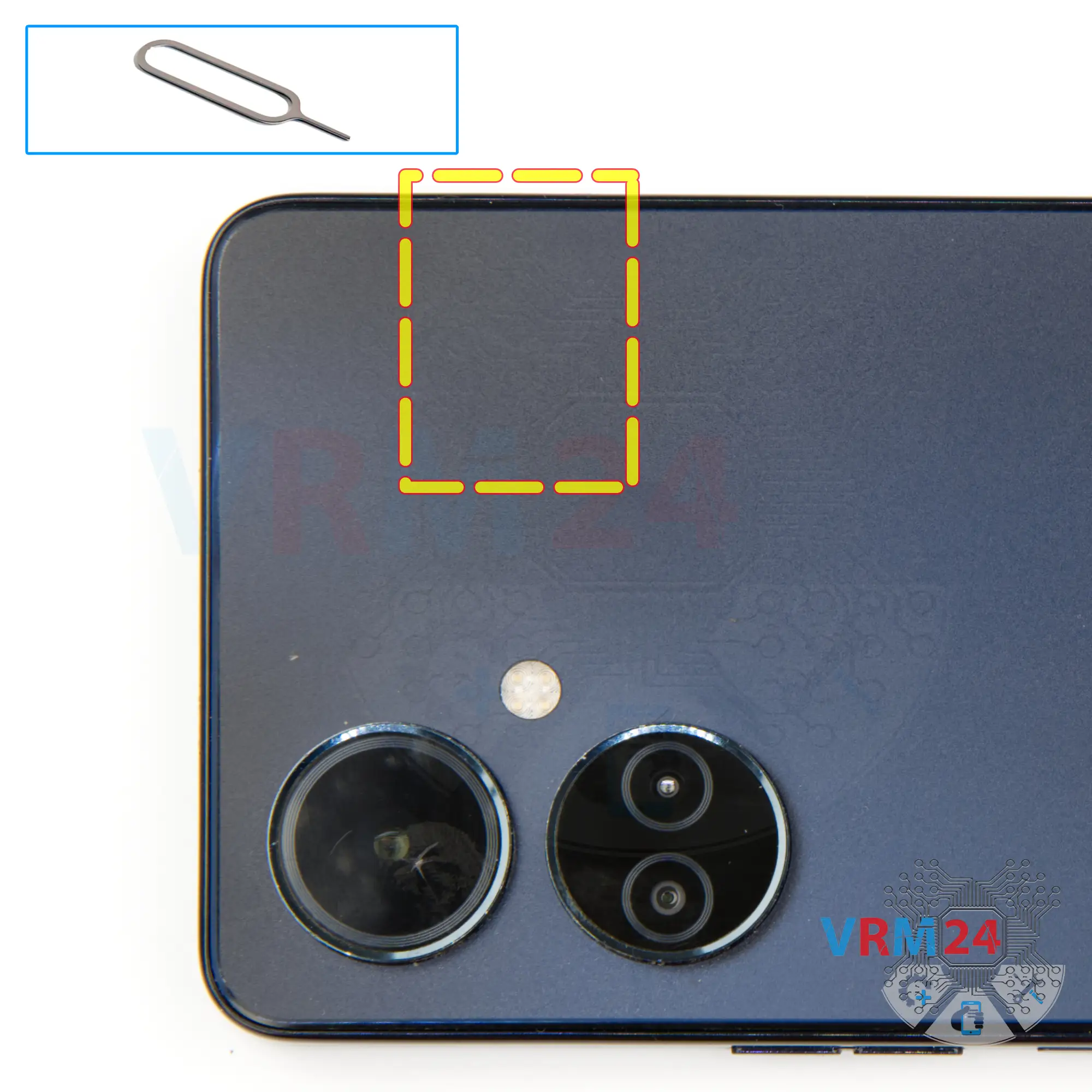
Step 2. Remove the tray
At the very beginning we need to remove the card tray for this we take a special tool, insert it into the hole and push out the combined card tray.

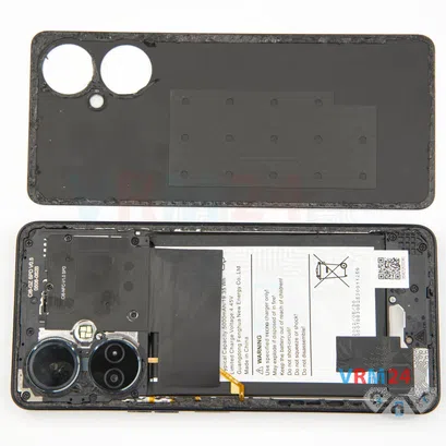

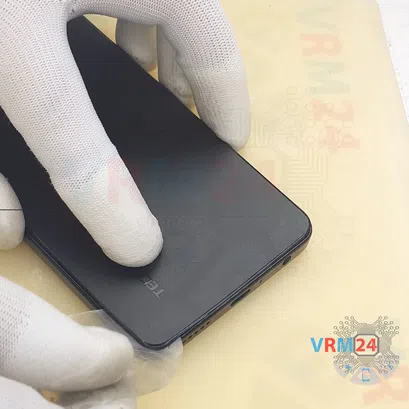


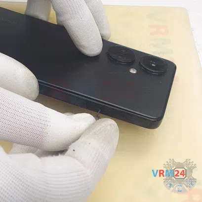
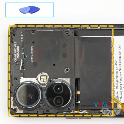
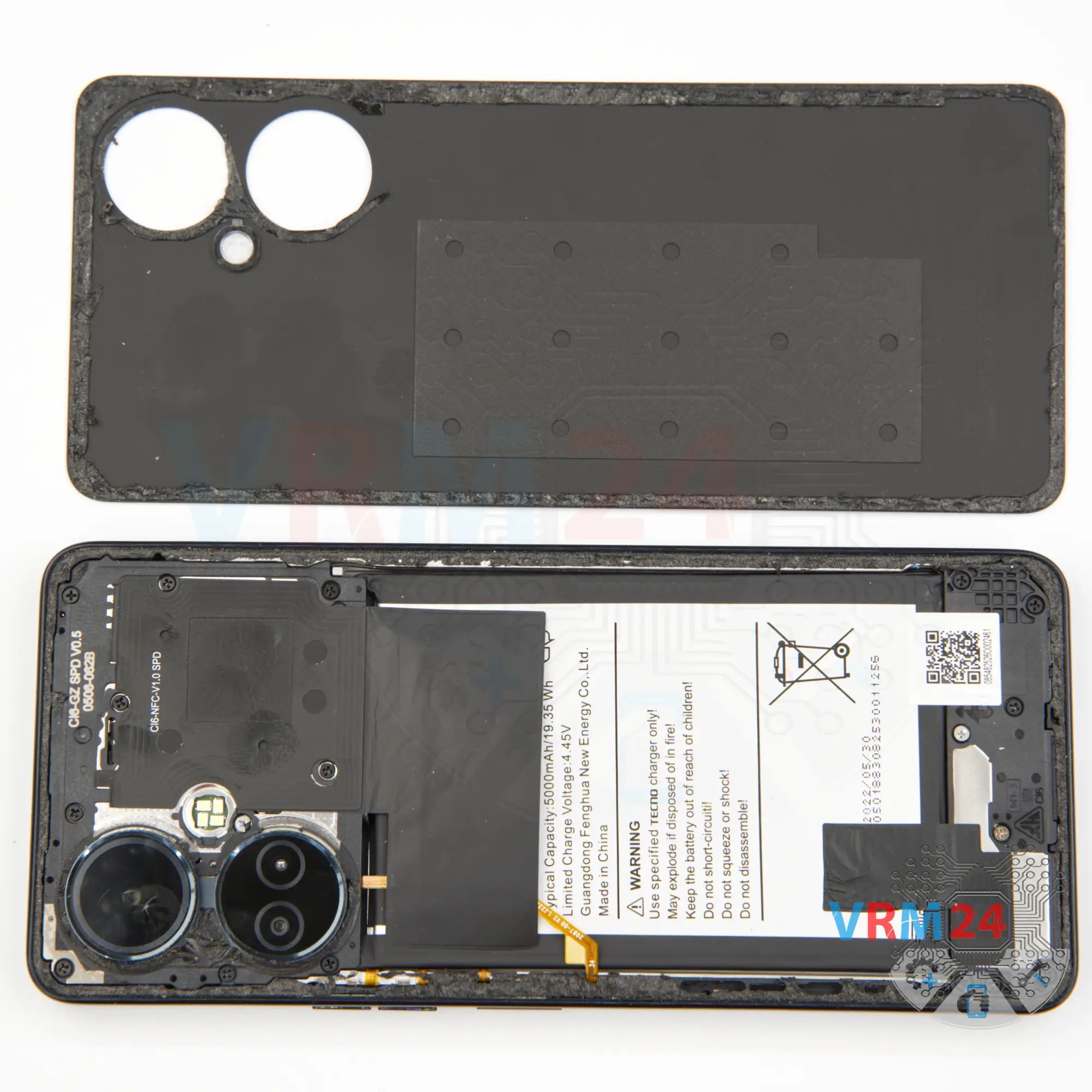
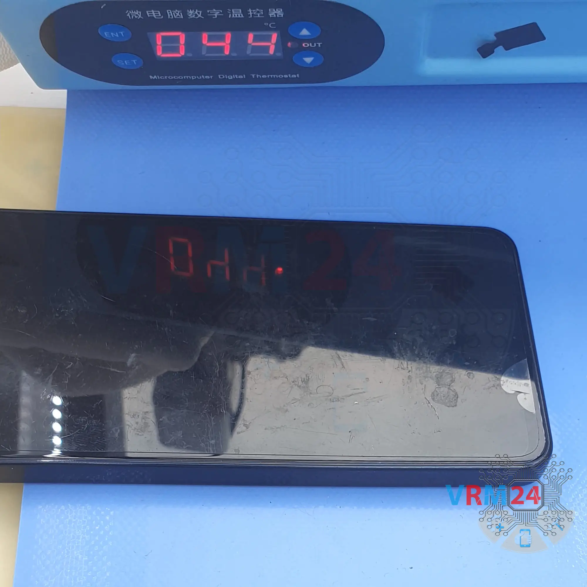
Step 3. Open the back cover
After that we need to heat the surface of the back cover to a temperature of about 65-70° C or 160° F. For this we use a heating mat you can use a hair dryer.
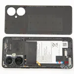
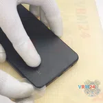
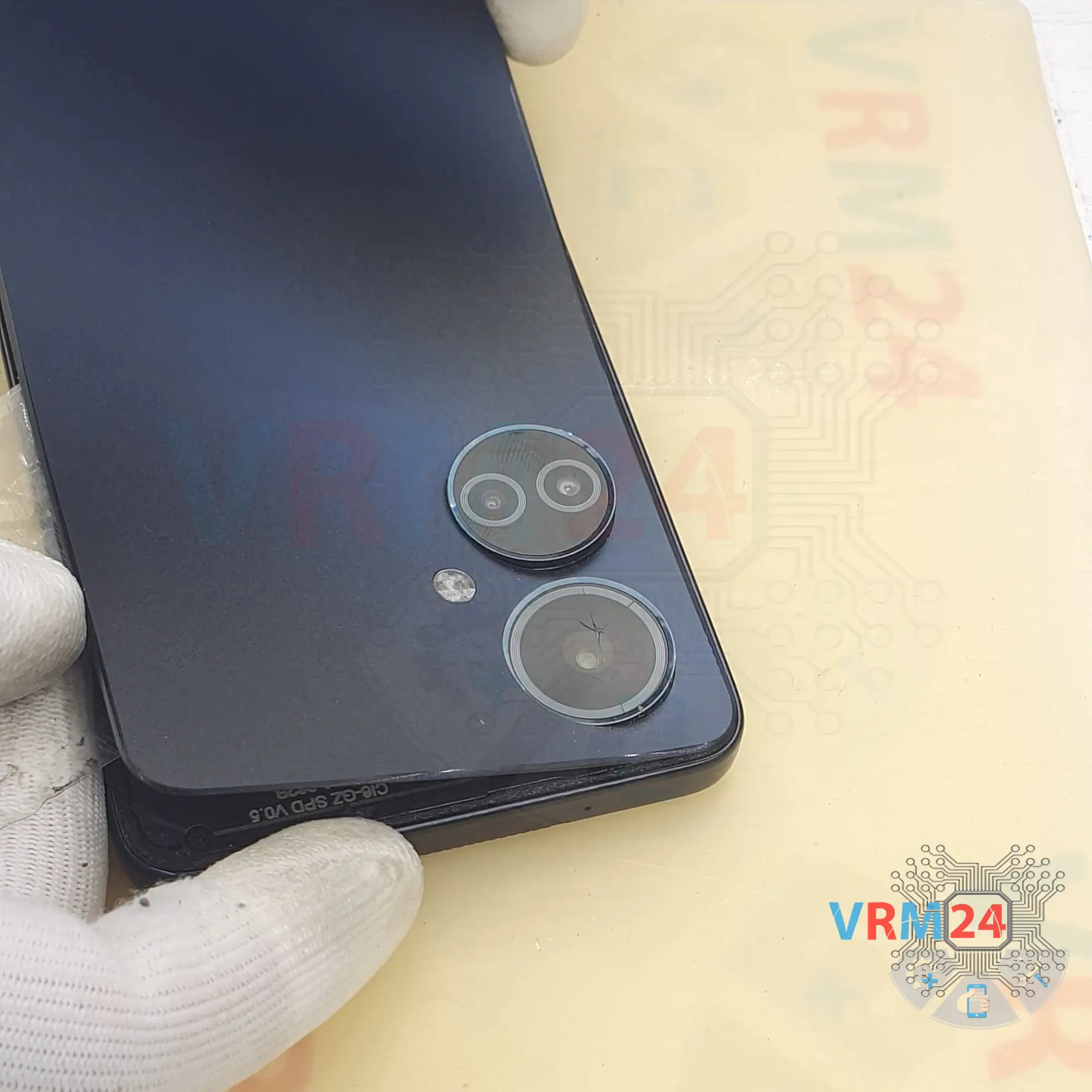
To remove the back cover, we will use a plastic film. It is a protective film from a new display or a film from the stationery store. Insert it into the gap between the middle cover and the back cover and run it along the length of the back cover to detach it.
We have a back cover that is separated from the cover of the cameras, so the back cover is taped around the cover of the cameras. We don't have to worry about the lenses, but the adhesive is tight in this area.


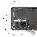
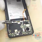
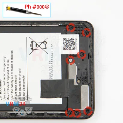
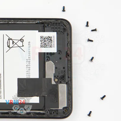
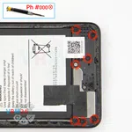
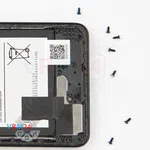
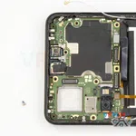
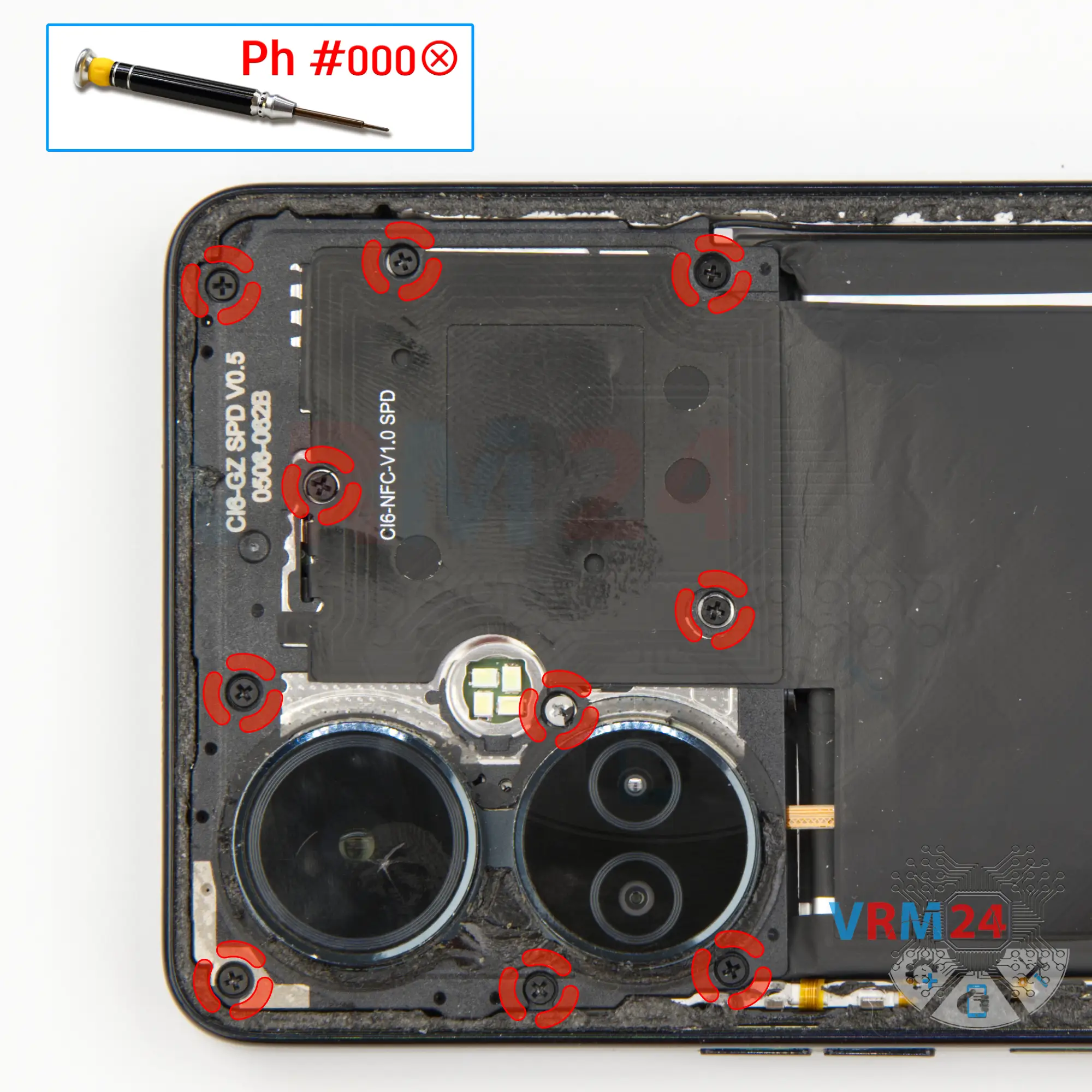
Step 4. Unscrew the screws
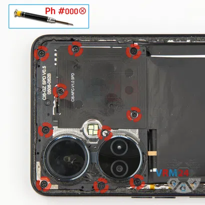
And we move on to unscrewing the screws at the top.
We use a 1.5mm Phillips screwdriver or #000 to remove the ten screws.
This will allow us to detach the cover and get to the battery connector which we will need to disconnect.

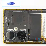
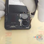
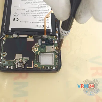
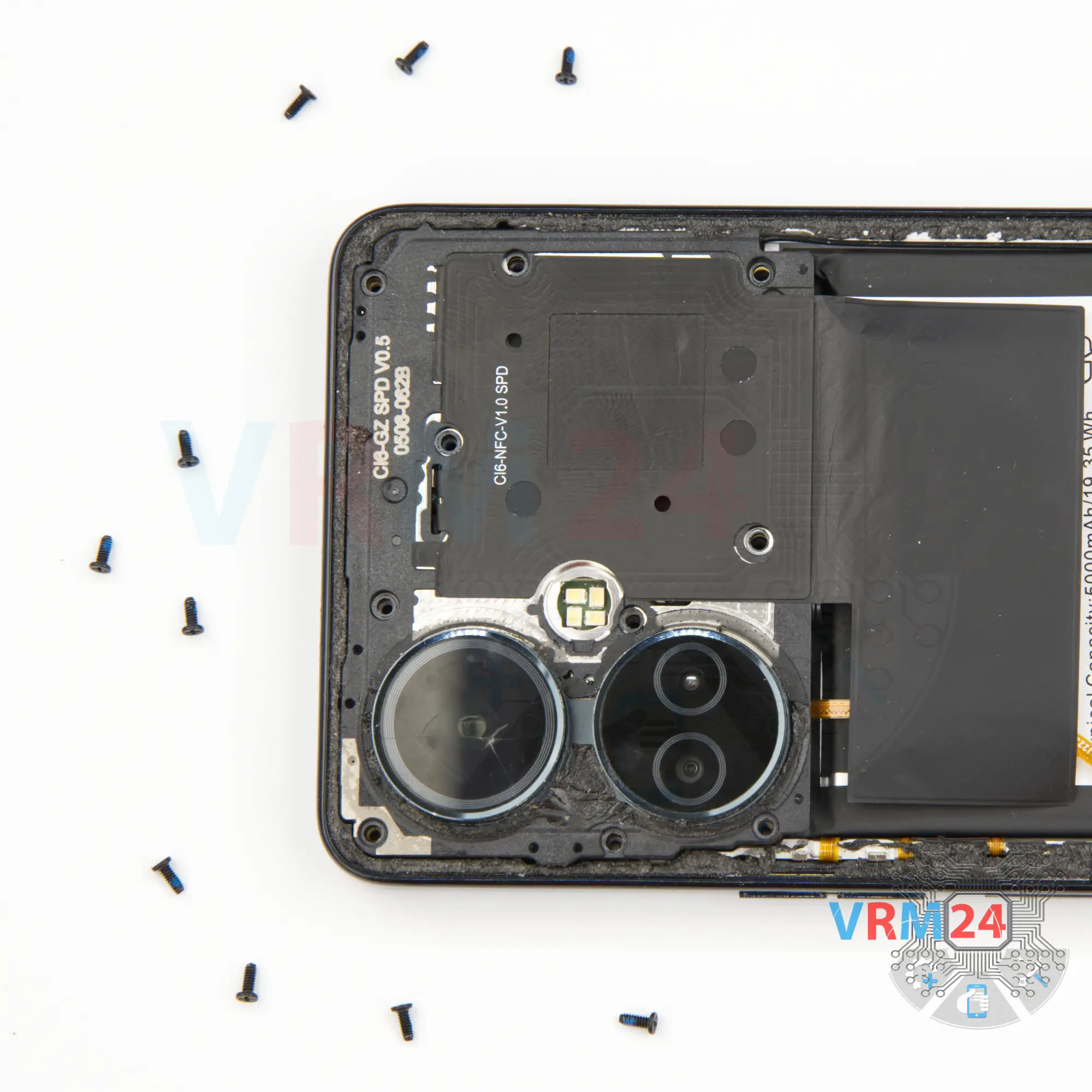
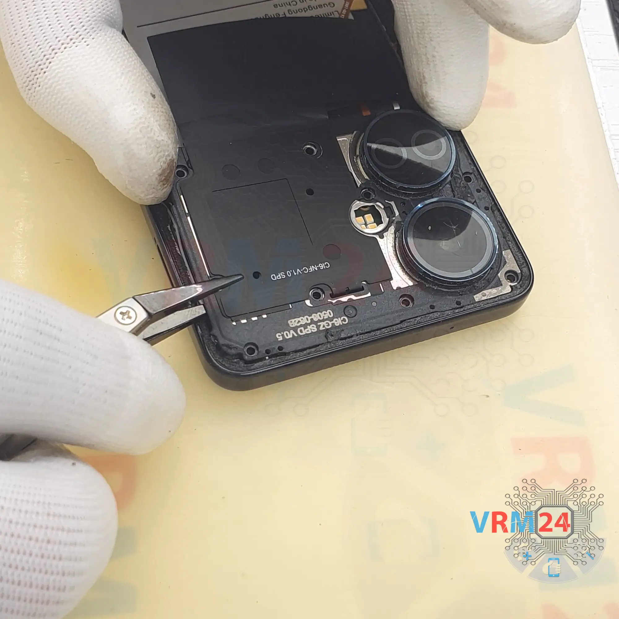
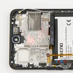
Step 5. Open the cover
And with a non-metal tool we have to detach the cover hiding the motherboard. The cover, by the way, also protects the cameras.


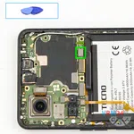
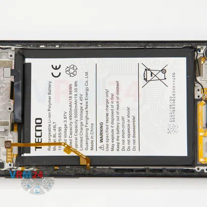
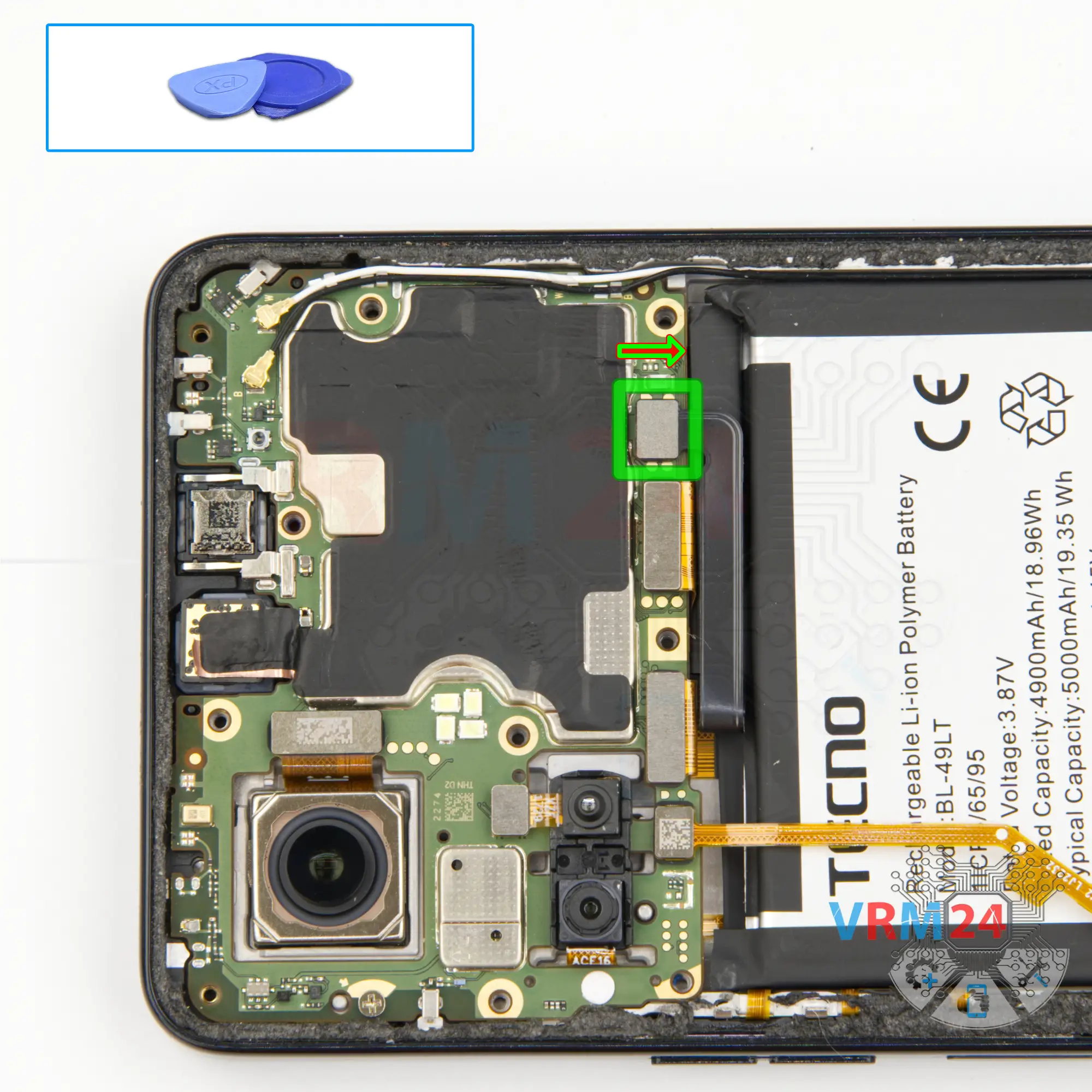
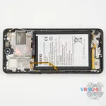
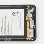
Step 6. Disconnect the battery connector
Disconnect the battery connector as soon as you can. Use a non-metallic or plastic tool to avoid any damage.
ℹ️️ The Tecno Camon 19 model has a battery BL-49LT with a capacity of 5000 mAh (also known as a rechargeable battery).


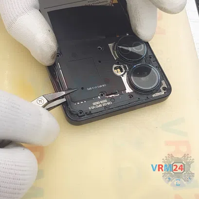
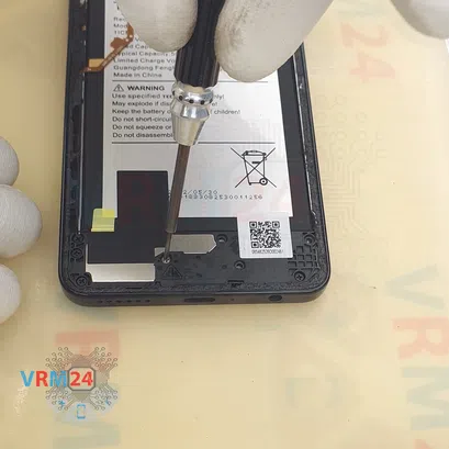
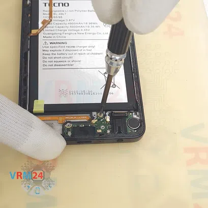
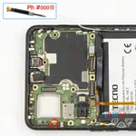
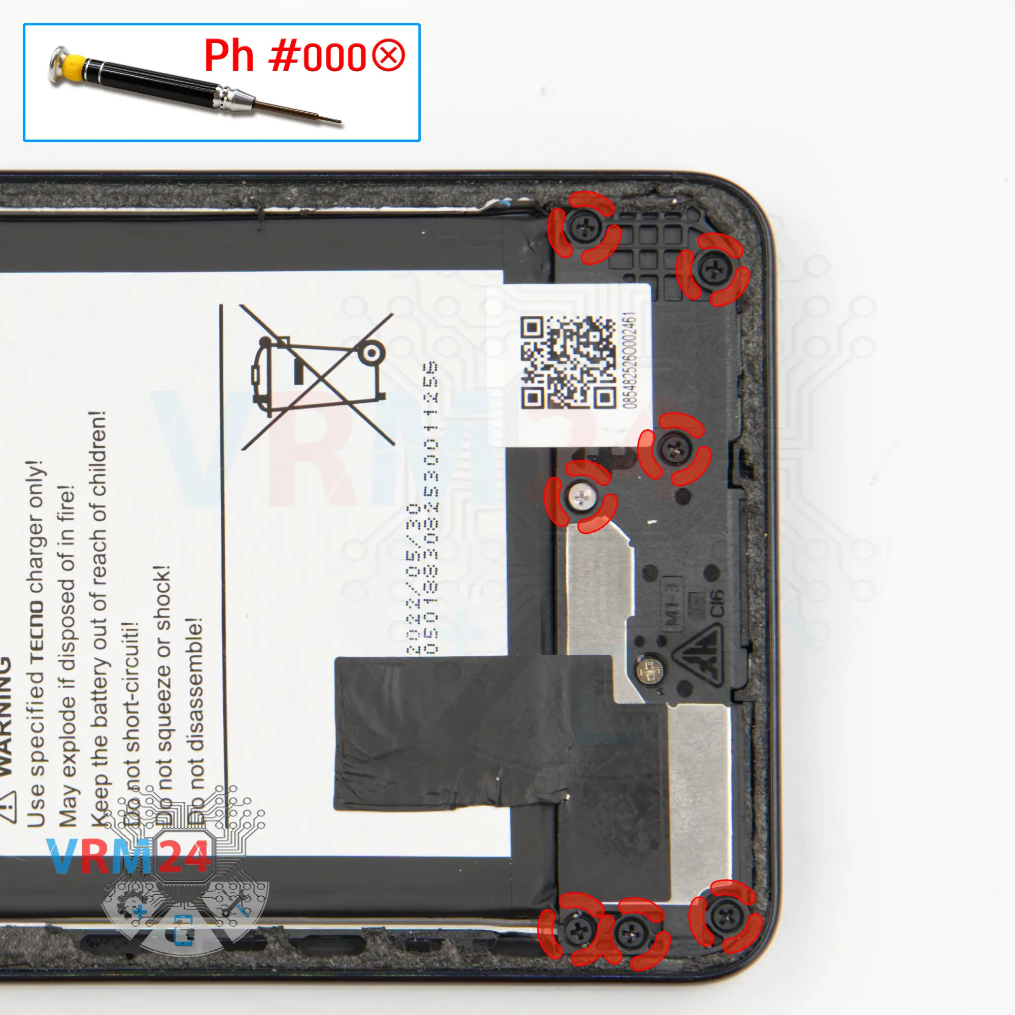
Step 7. Unscrew the screws
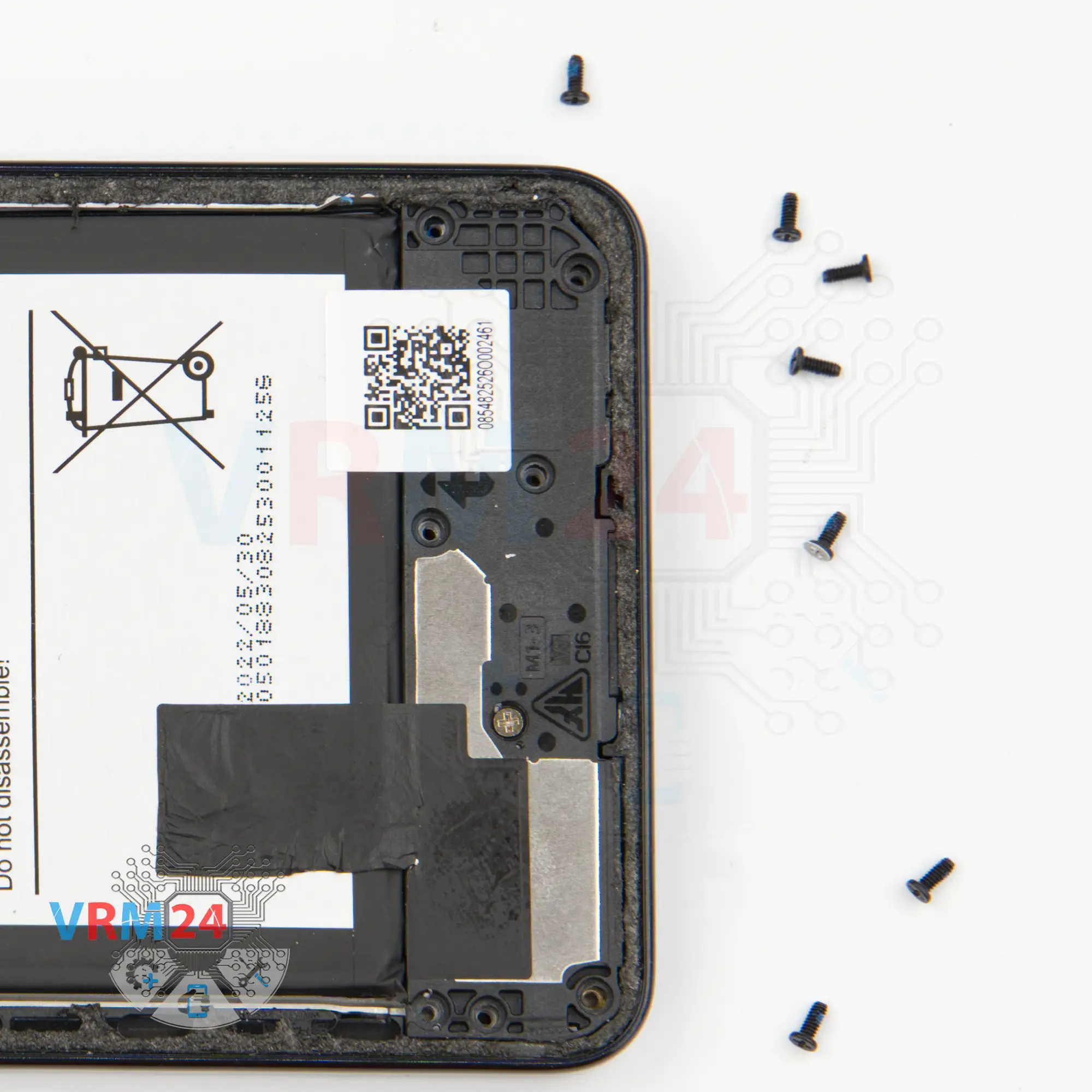
And we move on to unscrewing the seven black screws at the bottom. The screwdriver is the same 1.5mm Phillips.
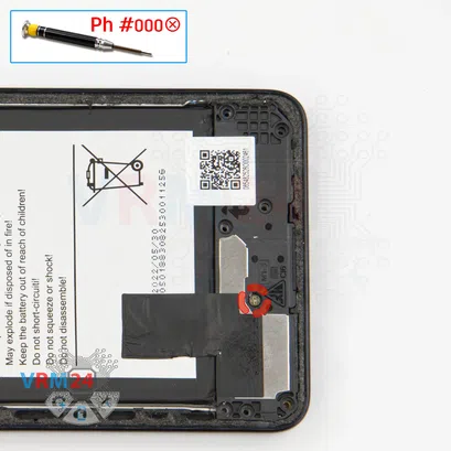
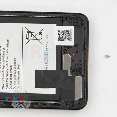
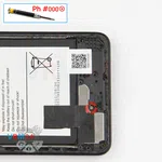
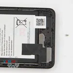

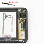
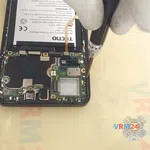
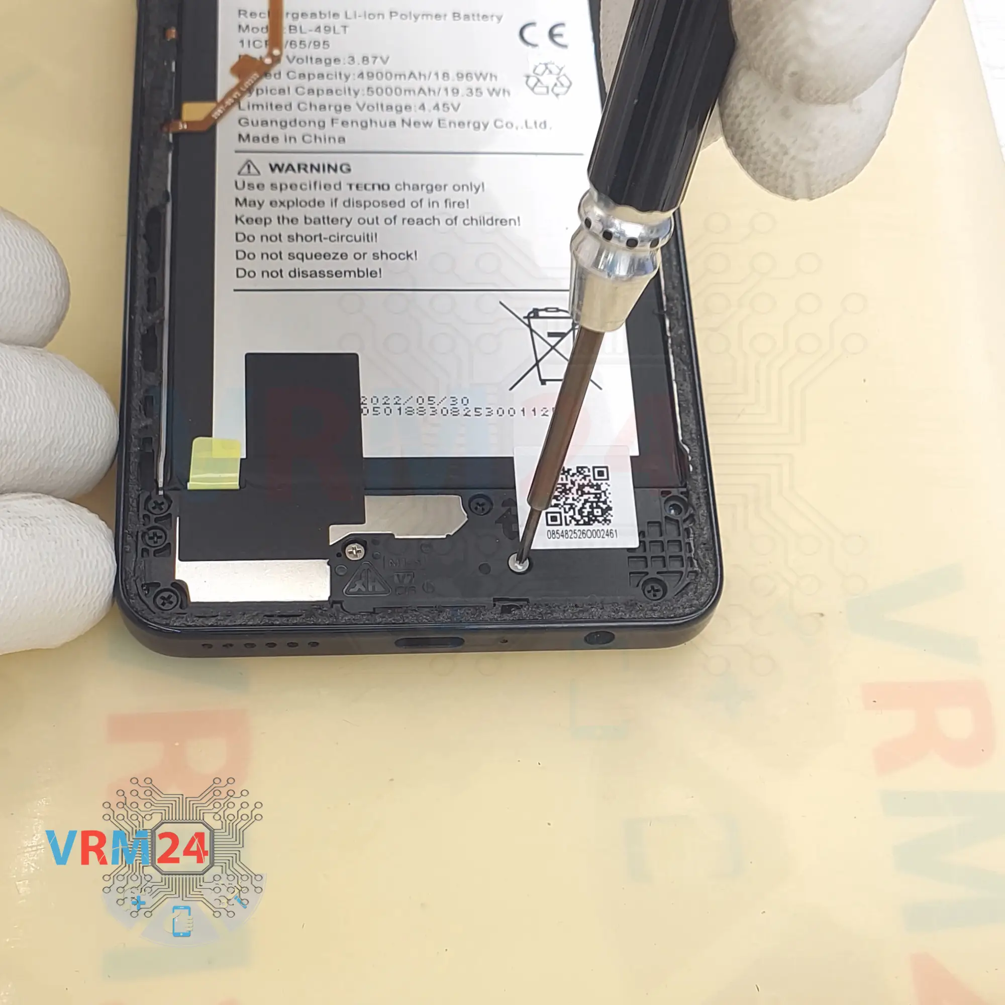
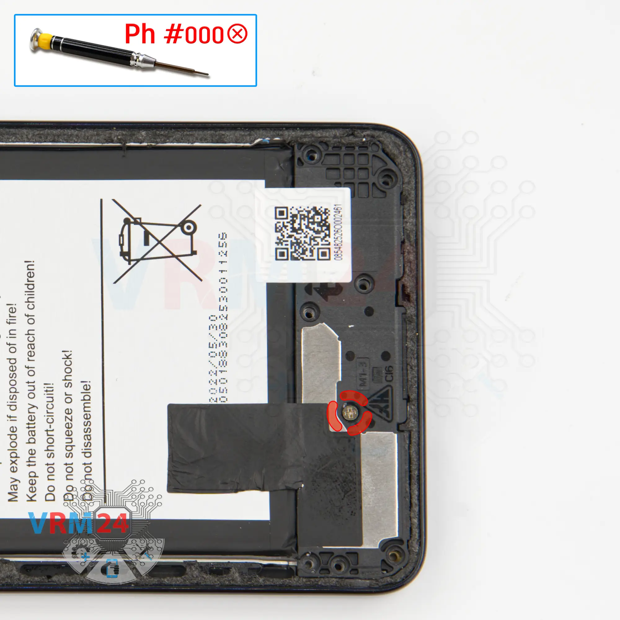
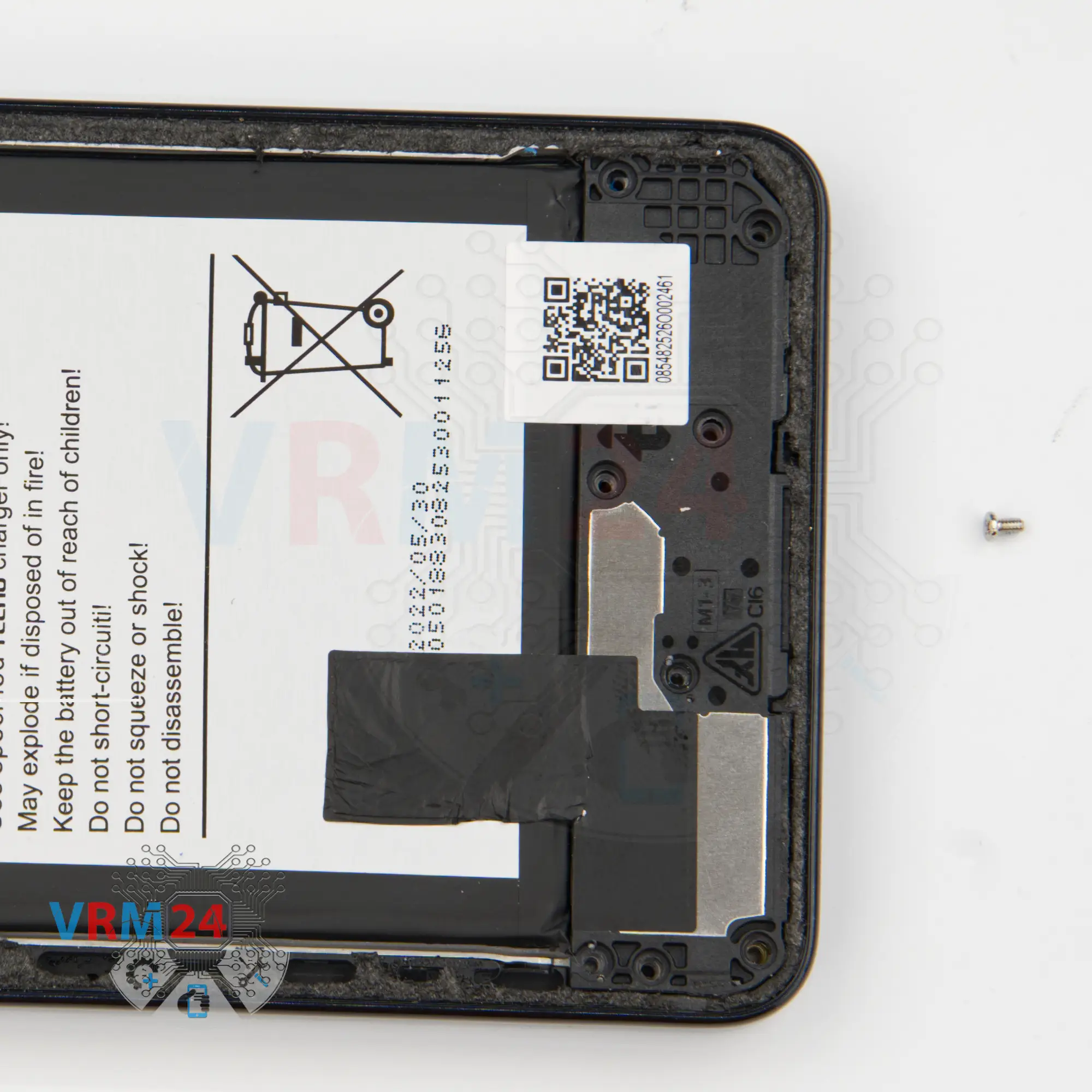
Step 8. Unscrew one screw
With a screwdriver Philips 1.5 mm or #000 we unscrew one silver screw. This screw is obviously different, so we recommend placing all of the screws on a special surface in an easy-to-remember order for reassembly.

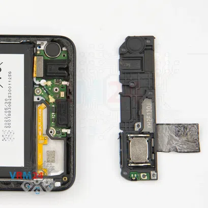
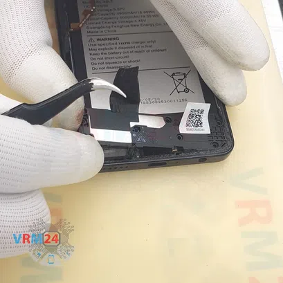


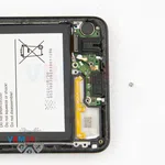
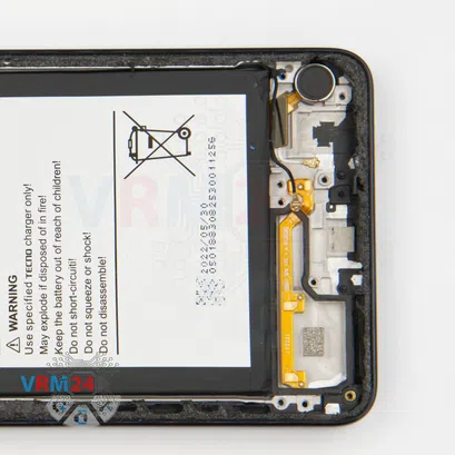
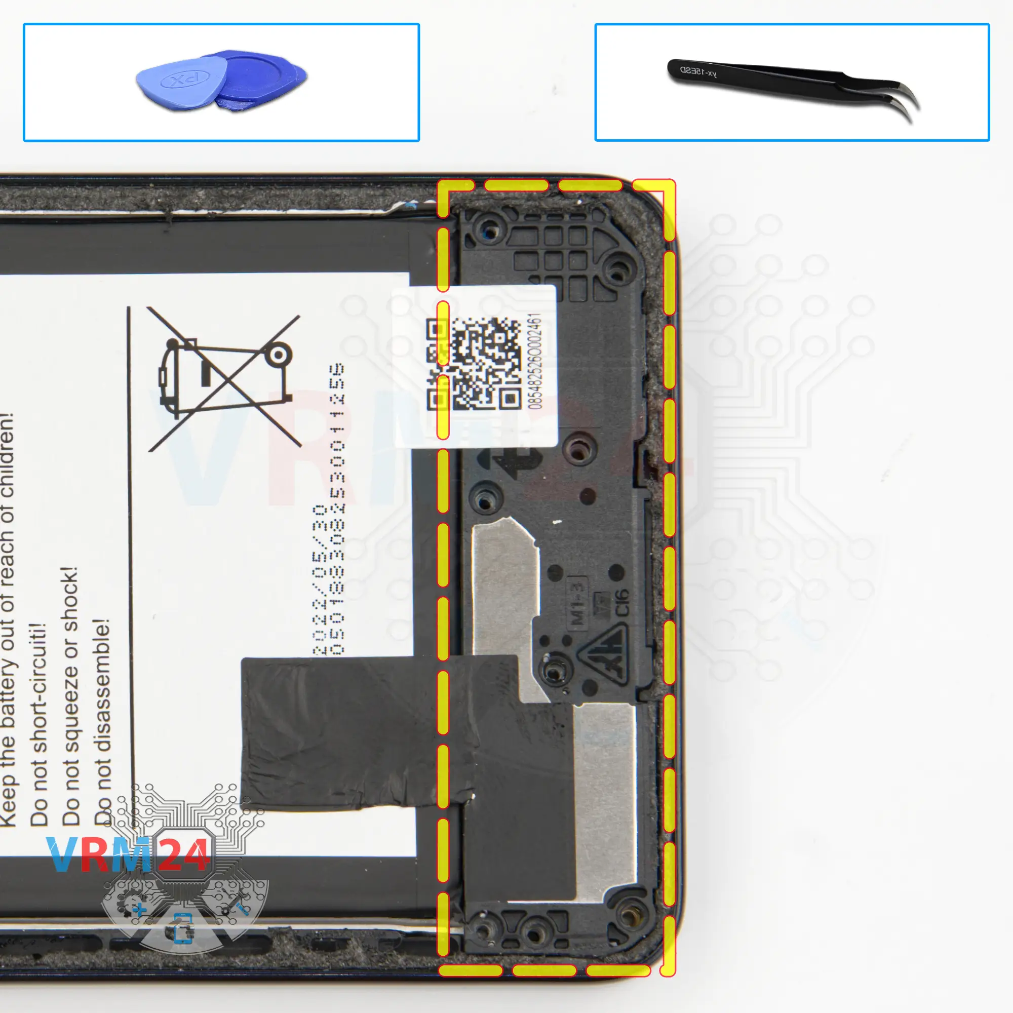
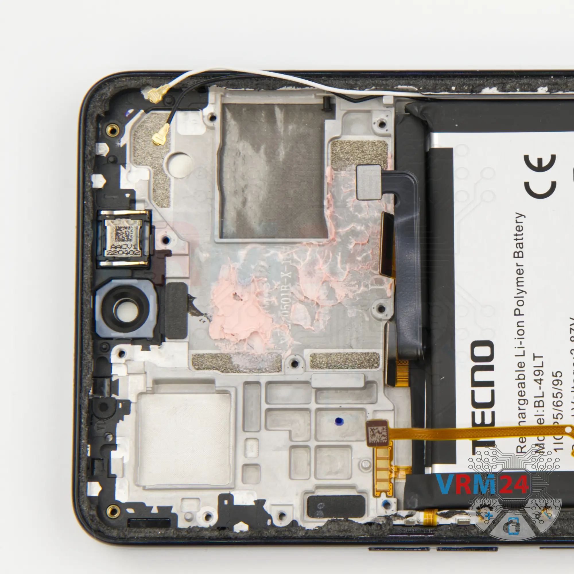
Step 9. Remove the loudspeaker
And we can detach the cover with the speaker.
We find a right and convenient place where we can hook the cover and lift it gently by rocking it, because it is slightly glued on the edge.
On the cover we also have a small board for the antennas.
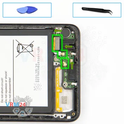


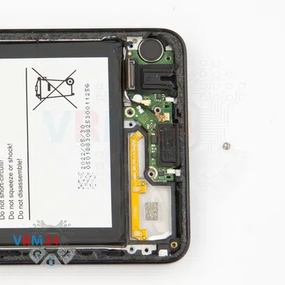
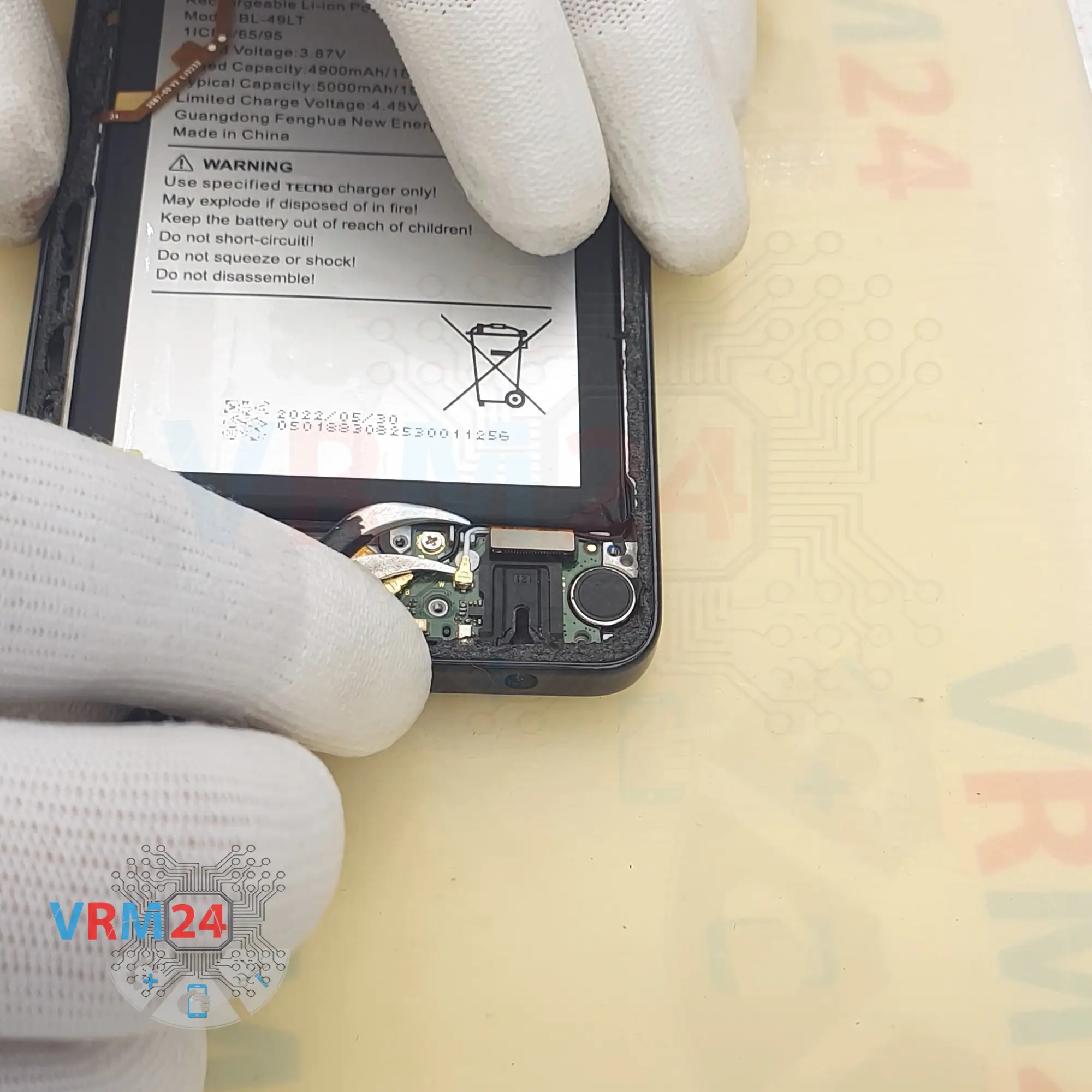
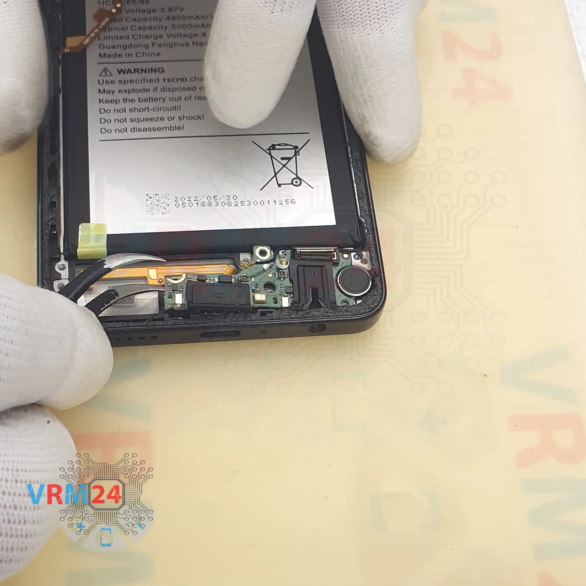
Step 10. Disconnect the connectors
We can disconnect the inter-board cable connector and the two connectors of the two coaxial cables. And we release the second cable from the clips on the sub-board.
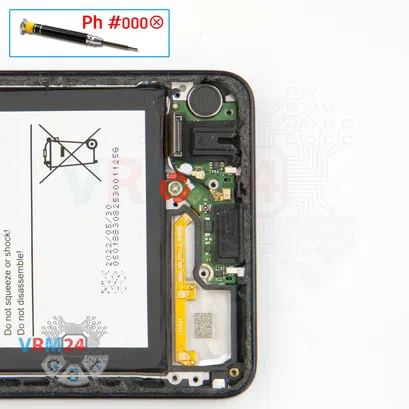
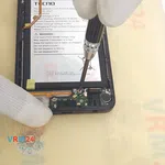
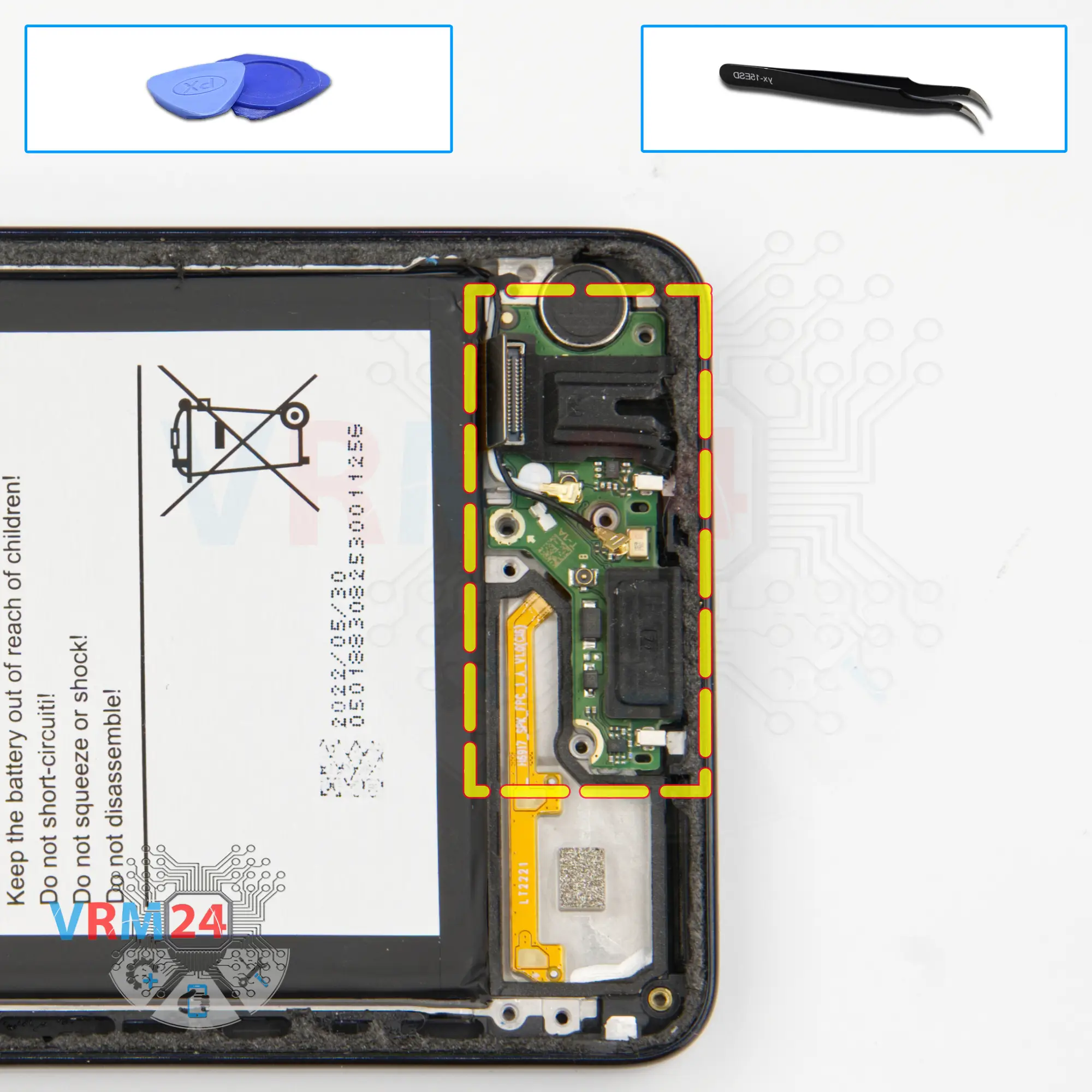
Step 11. Unscrew one screw
We need to unscrew one screw holding the sub-board. The screwdriver is the same 1.5mm #000 Phillips.
⚠️️ This screw is obviously different from the previous ones.
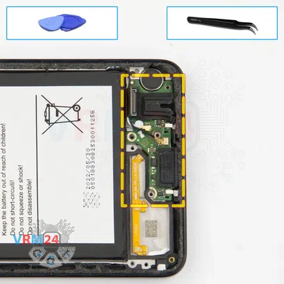
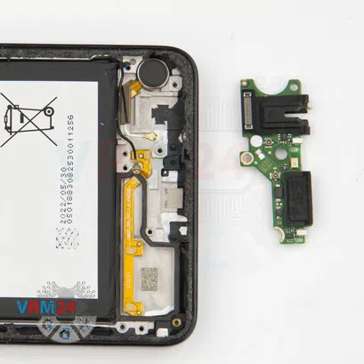


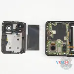
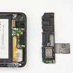
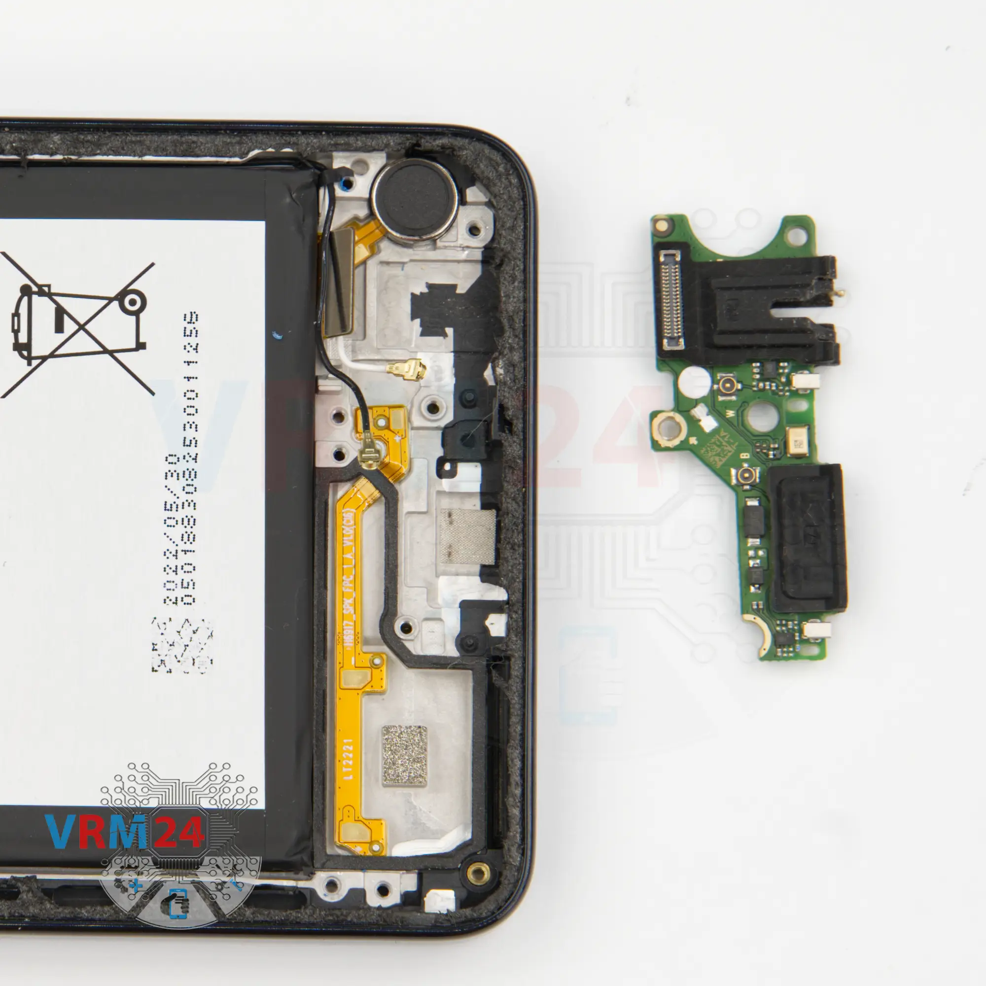
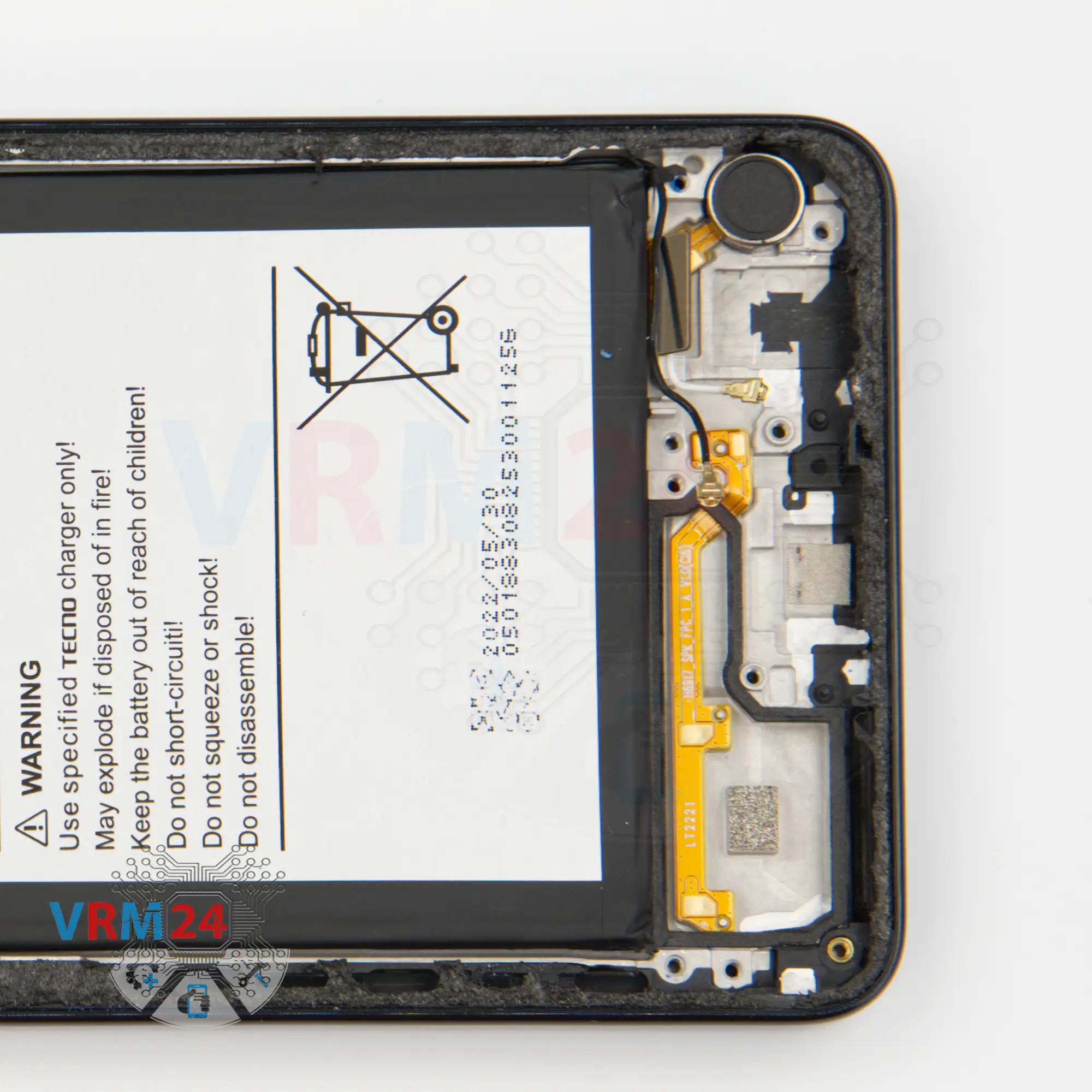
Step 12. Remove the sub-board
We can detach the sub-board by gently hooking the edge in the right place and pulling it out.
The sub-board is slightly recessed into the display frame.
On the sub-board we have the charging port, microphone, headset port, and other elements on the back side.
And the vibration motor remains in the display frame.

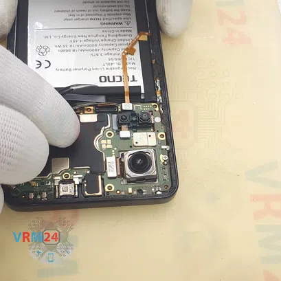


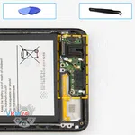
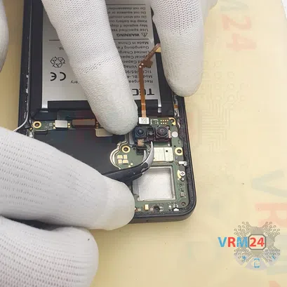
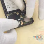
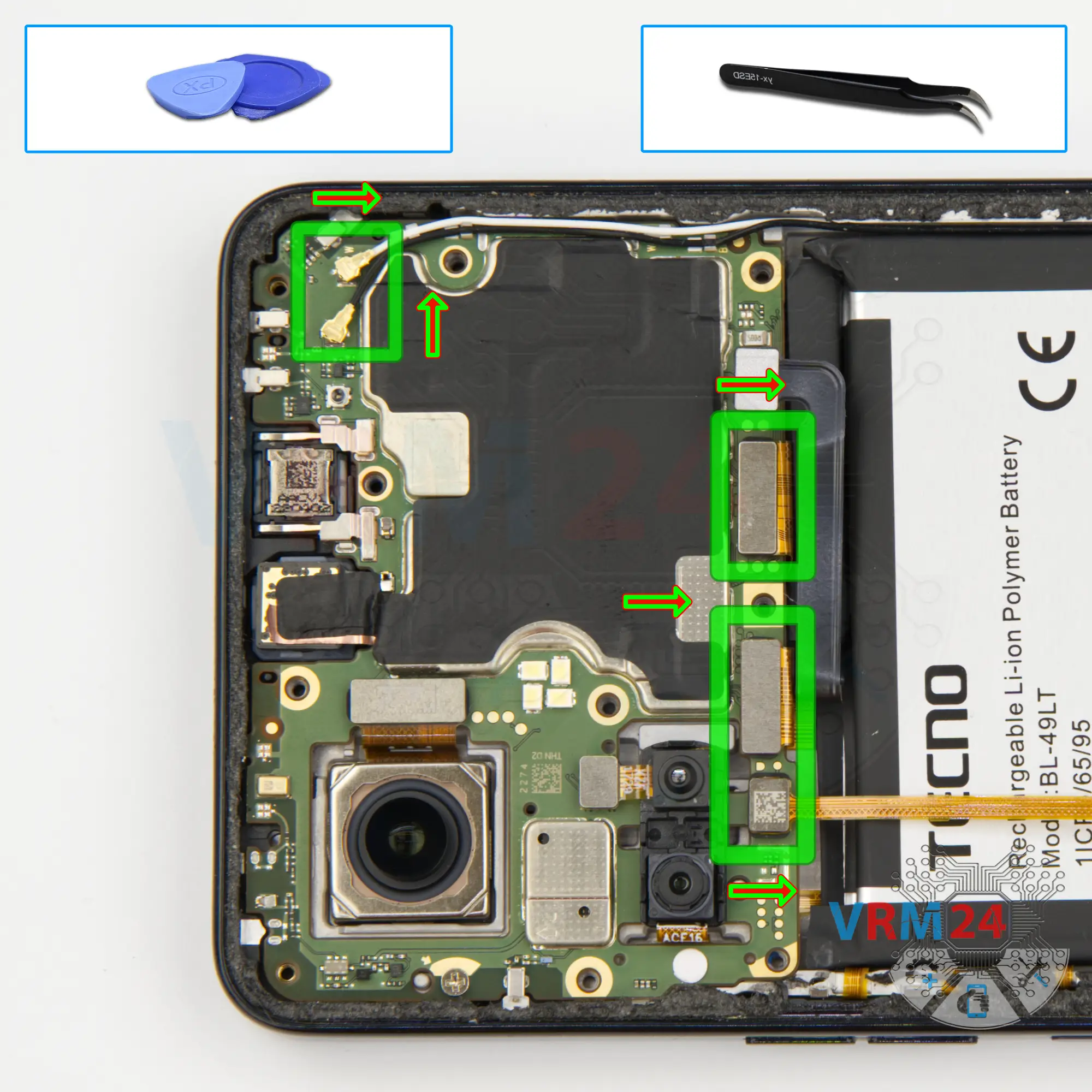
Step 13. Disconnect the connectors
After that we disconnect the connector of the inter-board cable and the connector to the display.
We disconnect the connector, most likely on the fingerprint sensor.
Then we disconnect the connectors of the two coaxial cables and release the cables themselves from the clips on the motherboard.


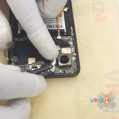
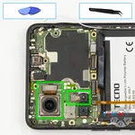

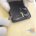
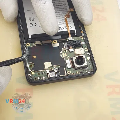
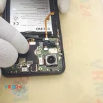
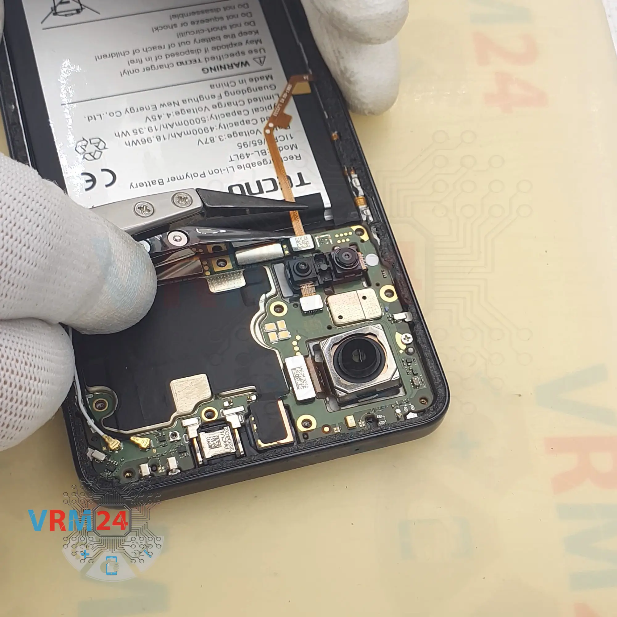
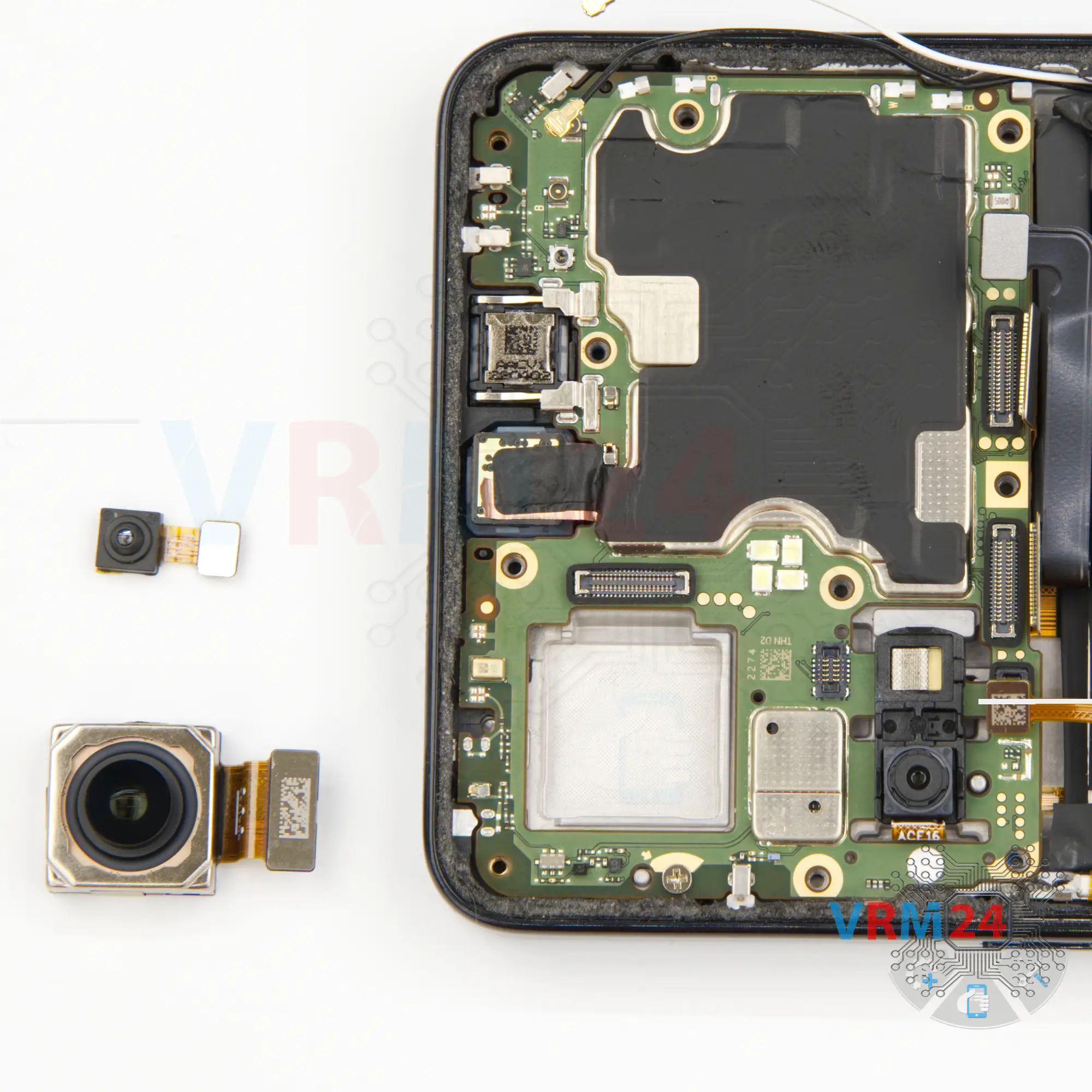
Step 14. Remove the cameras
And we can detach the rear cameras.
Carefully hold the body so that the camera does not fly out, at the same moment it is important not to touch the lenses, disconnect the connector and take out the camera.
Btw, the small camera is slightly taped to the black frame.
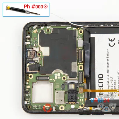
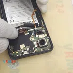
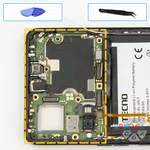
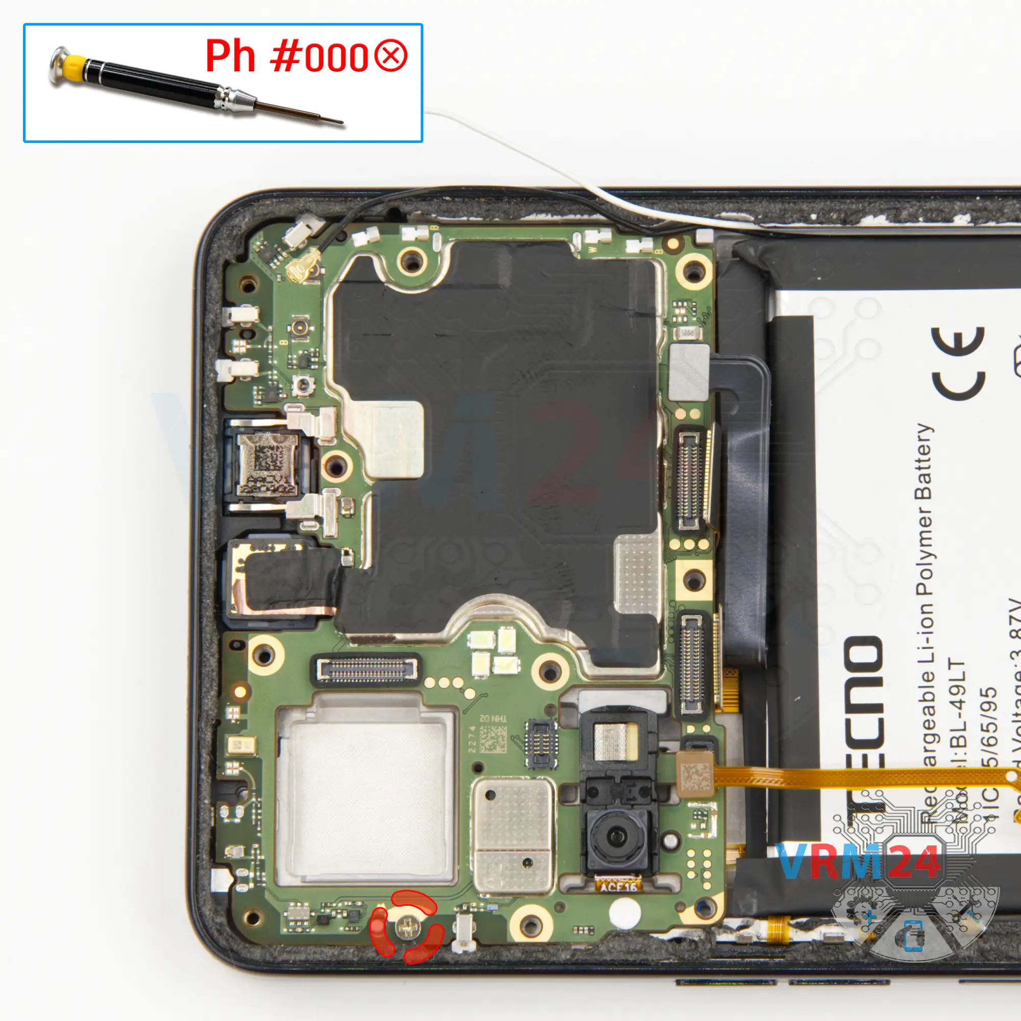
Step 15. Unscrew one screw
We unscrew one screw securing the motherboard.
The screwdriver is the same 1.5mm Phillips #000.
And we also have a different screw than the previous ones.


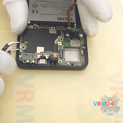


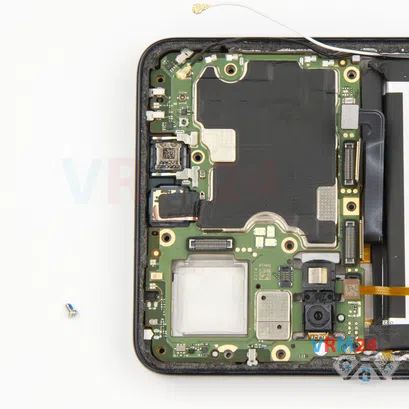
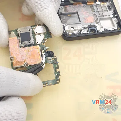
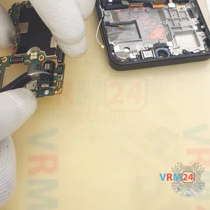
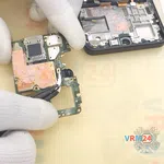
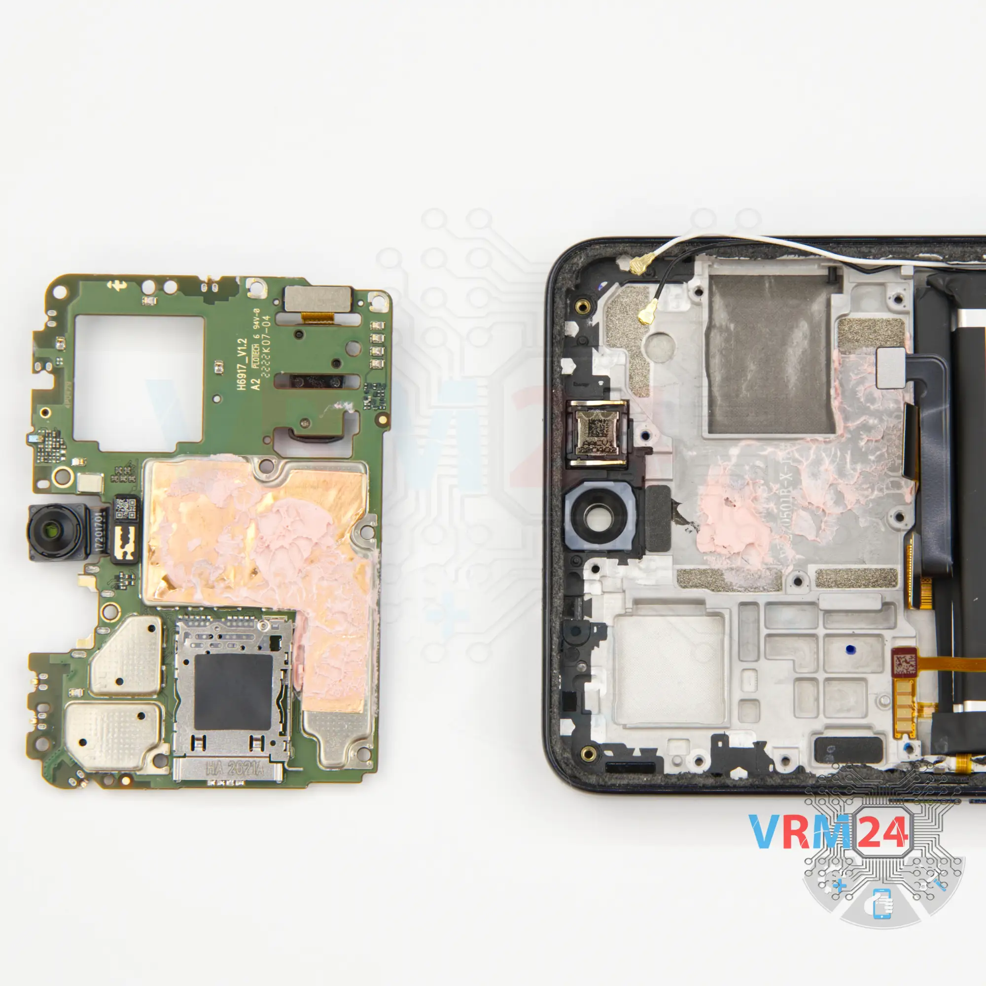
Step 16. Remove the motherboard
We can detach the motherboard. Find the right and convenient place to hook the motherboard.
And take out the circuit board and turn it over.
⚠️️ Do not bend the circuit board when removing it or push tools under it. Unbeknownst to yourself, you can damage components or cables from the inside.

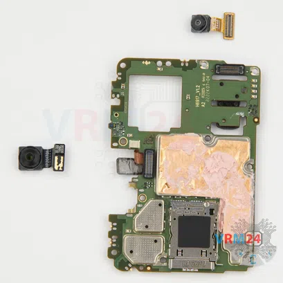


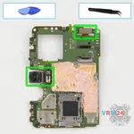


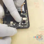
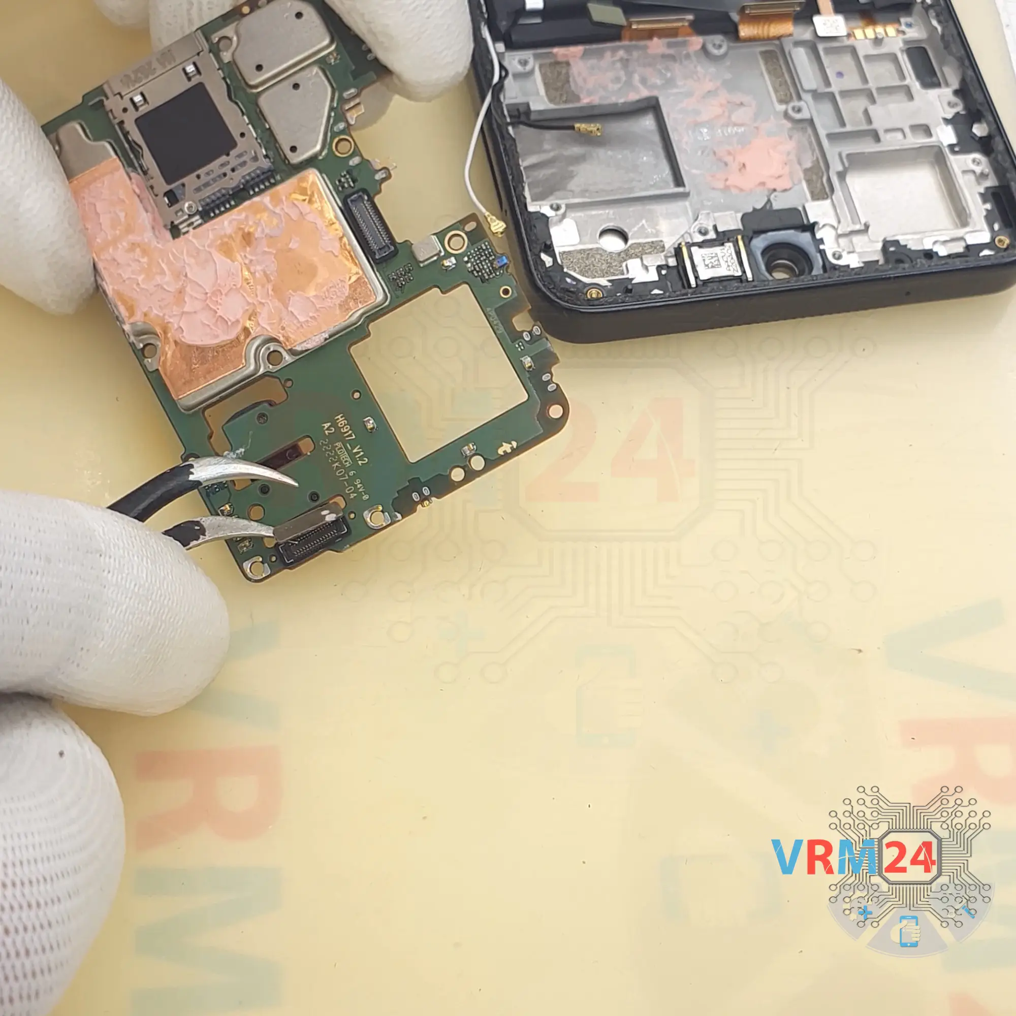
Step 17. Remove the cameras
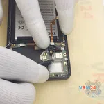
Then we disconnect the front camera connector and peel off the copper heat dissipating coating.
And we disconnect the last rear camera connector and we need to pass the rear camera connector through the hole in the motherboard to remove the camera.
Carefully pass the connector through so as not to damage the cable.
By the way, the rear camera is slightly glued to the motherboard.


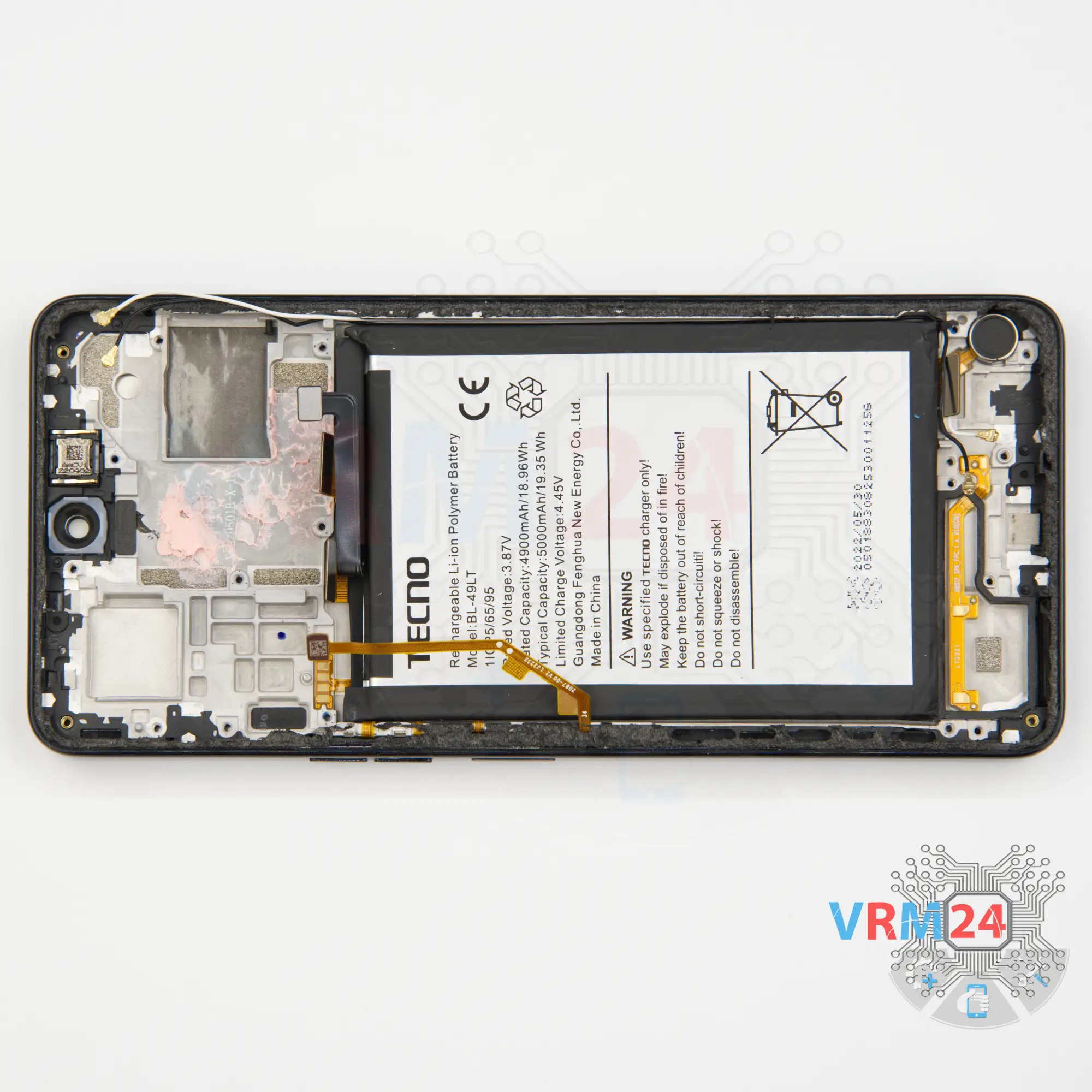
Step 18. In the display frame remained
ℹ️️ In the display frame remained: the earpiece speaker, battery, vibration motor, side buttons, coaxial cables.
Detailed disassembly instructions of Tecno Camon 19 in the video, made by our mobile repair & service center:
If you have a question, ask us, and we will try to answer in as much detail as possible. If this article was helpful for you, please rate it.

Disassembling\Repair has medium complexity and takes about minutes in time.
Our manual is suitable for all models Tecno Camon 19 released for markets in different countries.
Back to the list