

Recommended tools
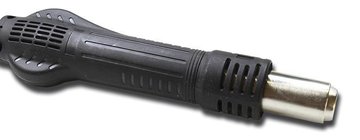
Heat gun
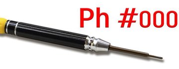
Screwdriver Phillips #000
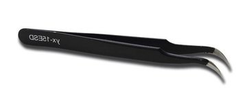
Tweezers
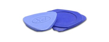
Non-metallic tool
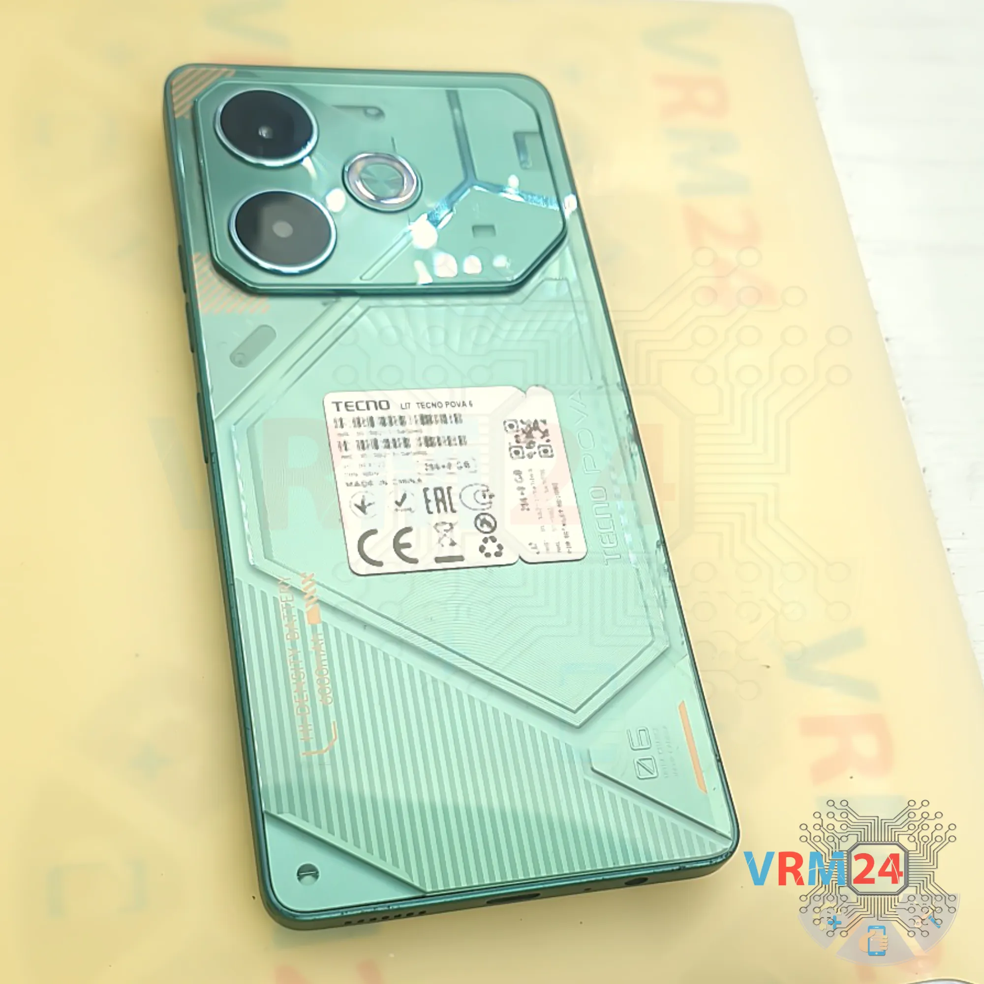
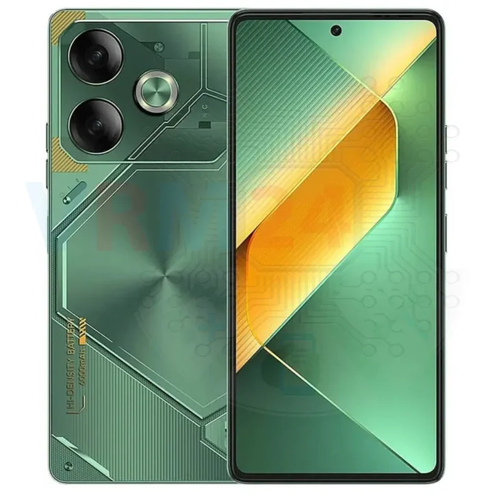
Disassembly/Repair of the mobile device Tecno Pova 6 (Tecno Pova 6 l17) with each step description and the required set of tools.
6753
Views
3
Likes
—
Share
0
Questions

Step 1.
Before disassembling!
Hi everyone, today we’re going to take apart the Tecno POVA 6.
⚠️ Before disassembling, do not forget to turn your phone off.
Step 2.
Remove the tray
First of all, we need to remove the card tray.
To do this, we use a special eject tool, insert it into the hole, and carefully push the card tray out.
⚠️ If the tray doesn’t come out easily, we can additionally use tweezers.
Step 3.
Open the back cover
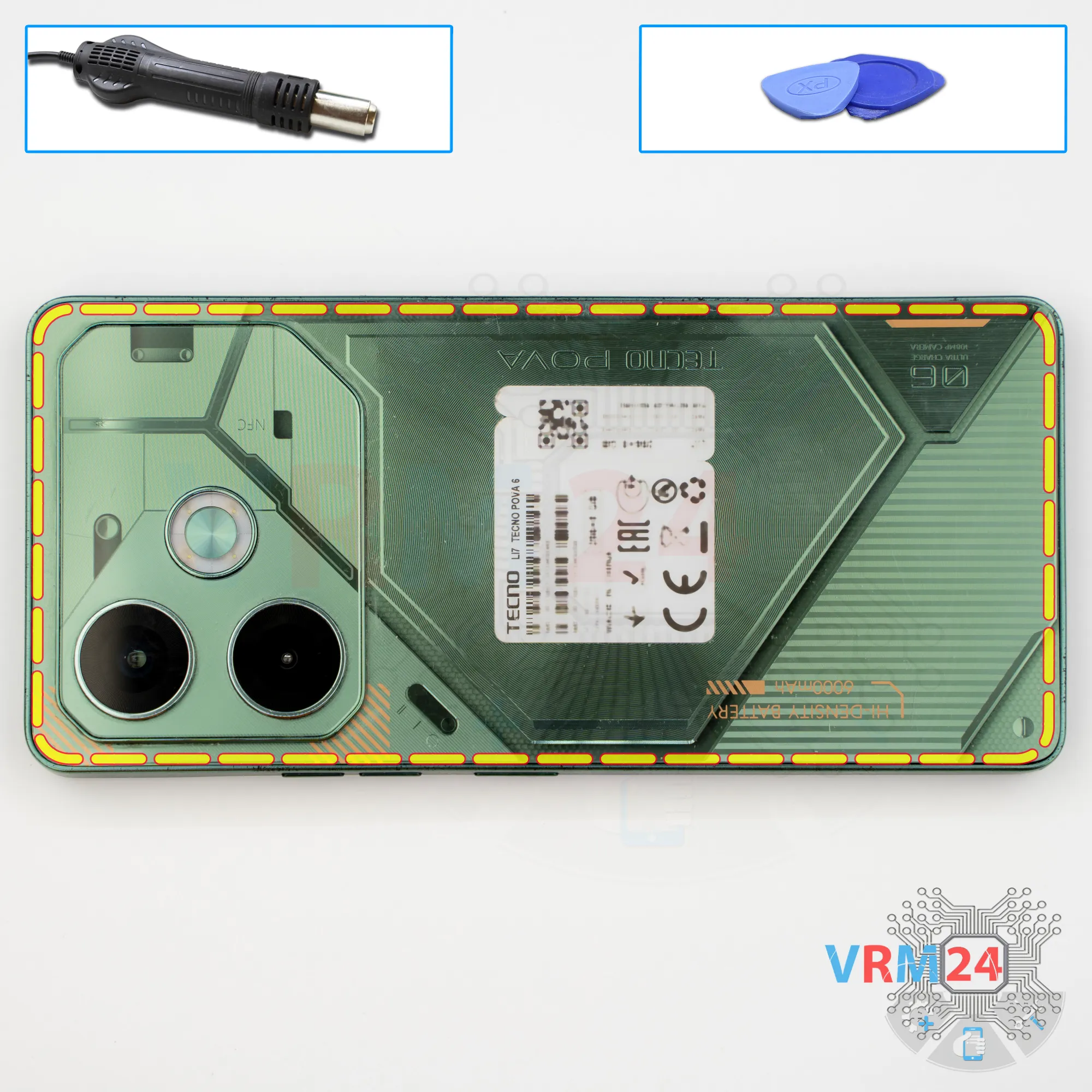
Next, we need to heat the surface of the back cover to a temperature of approximately 70 degrees Celsius, or about 160 degrees Fahrenheit.
For this, we use a heating mat, but you can also use a hair dryer.
After about 10 minutes, we can move on to removing the back cover.
For this, we use a thin plastic film, insert it into the gap between the back cover and the midframe, and carefully run it along the edge, cutting through the adhesive layer.
As always, we need to be careful around the camera area so we don’t accidentally touch the lenses.
Also, we shouldn’t insert the film too deep inside, since we don’t know exactly what is located under the back cover.
Step 4.
Protecting camera lenses
After that, we need to cover the camera lenses. For this, we use a special protective film.
Please note that we apply the film not on the lenses themselves, but on the rim around them.
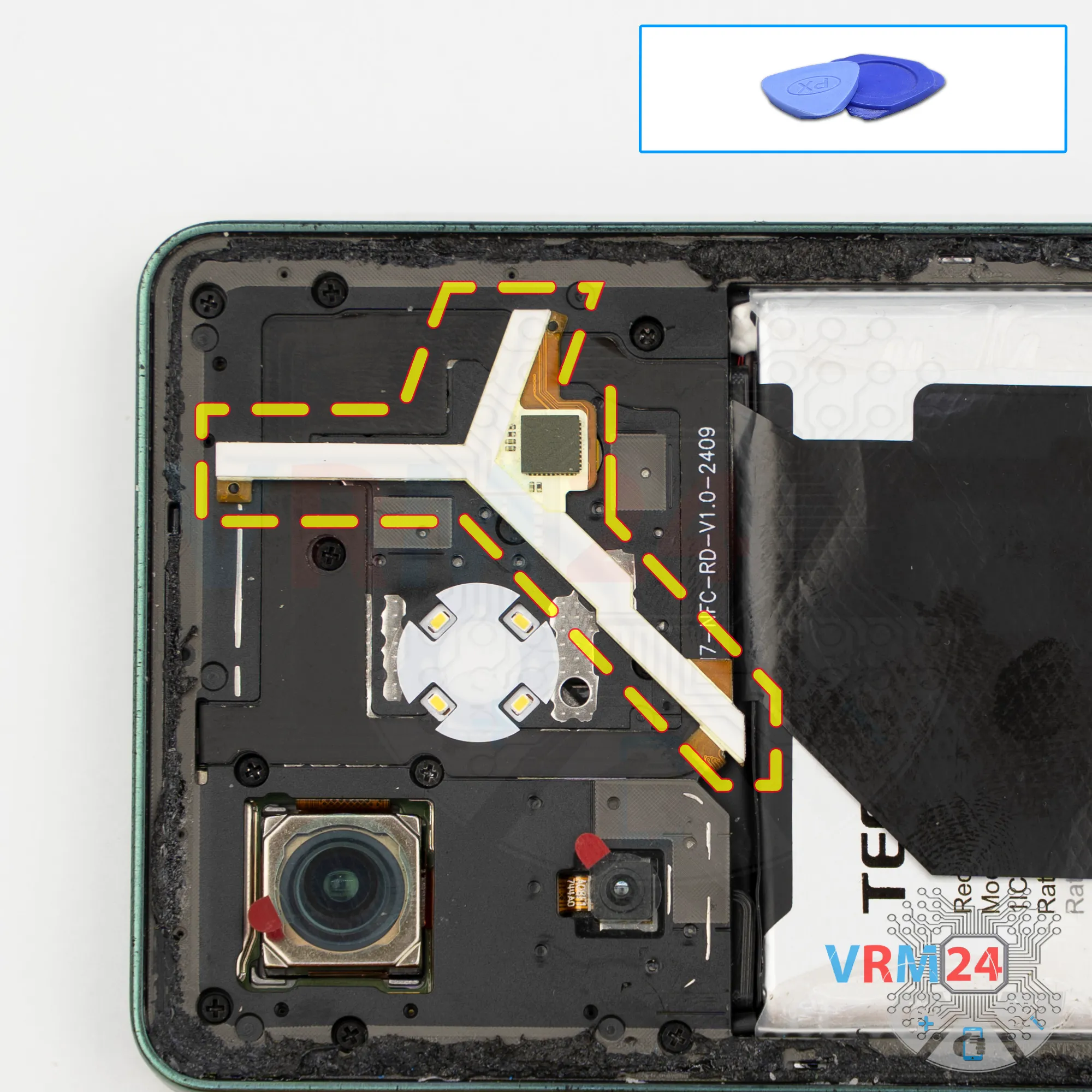
Also pay attention to how the LED backlight strips look on this model. We need to be careful, because there are screws located underneath them.
Step 5.
Unscrew the screws
Accordingly, we move on to removing the screws. For this, we use a 1.5 mm Phillips screwdriver, or a Philips #000.
Carefully remove the screws and place them on a special surface in a specific order. Very often, screws do not thread well if they are installed in the wrong holes.
If the screws don’t come out easily and get stuck, we can additionally use tweezers.
Step 6.
Unscrew the screws
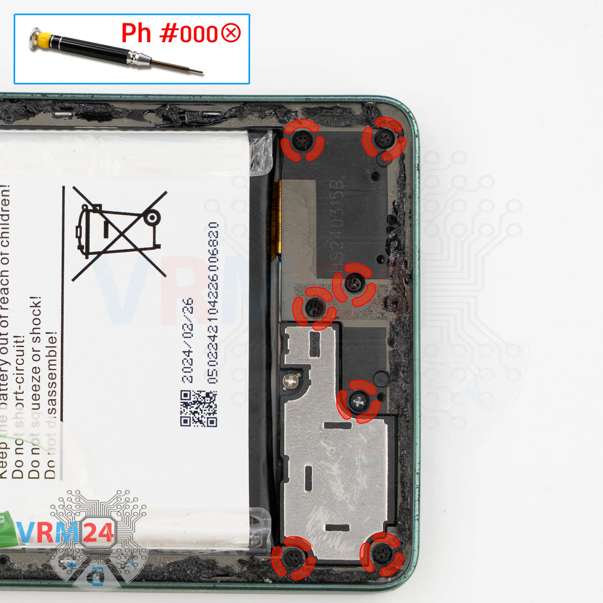
After that, we move on to removing the screws in the lower part.
Please note that some screws are different, so it’s very important to remember their correct positions.
Step 7.
Open the mid-frame
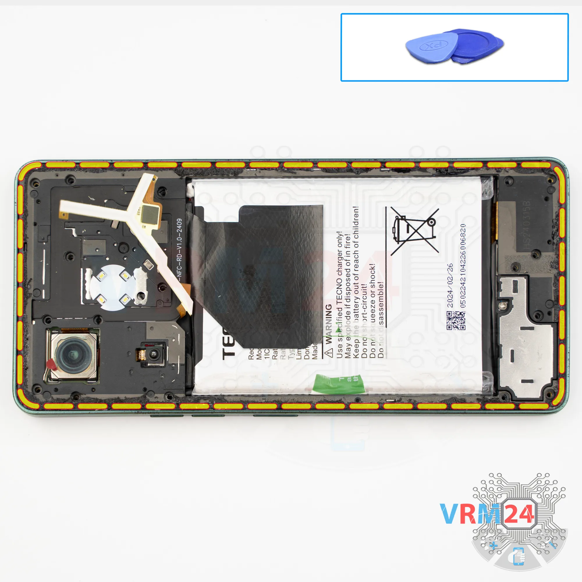
Once the screws are removed, we proceed to disconnect the midframe.
To do this, we use a thin plastic film, insert it into the gap between the midframe and the display frame near the card tray opening, carefully run it along the edge, release several clips, and then switch to a thicker tool.
As always, the cover is firmly held along the edges. And, as always, we need to be careful around the side buttons and along the edge of the display so we don’t accidentally damage it.
So, we carefully work our way around the edge. There’s no need to rush—don’t use force, so as not to damage the display.
We also need to keep in mind that when we remove the midframe, the backlight or flash flex cable is positioned in such a way that if we suddenly lift the cover, we can tear this cable.
Step 8.
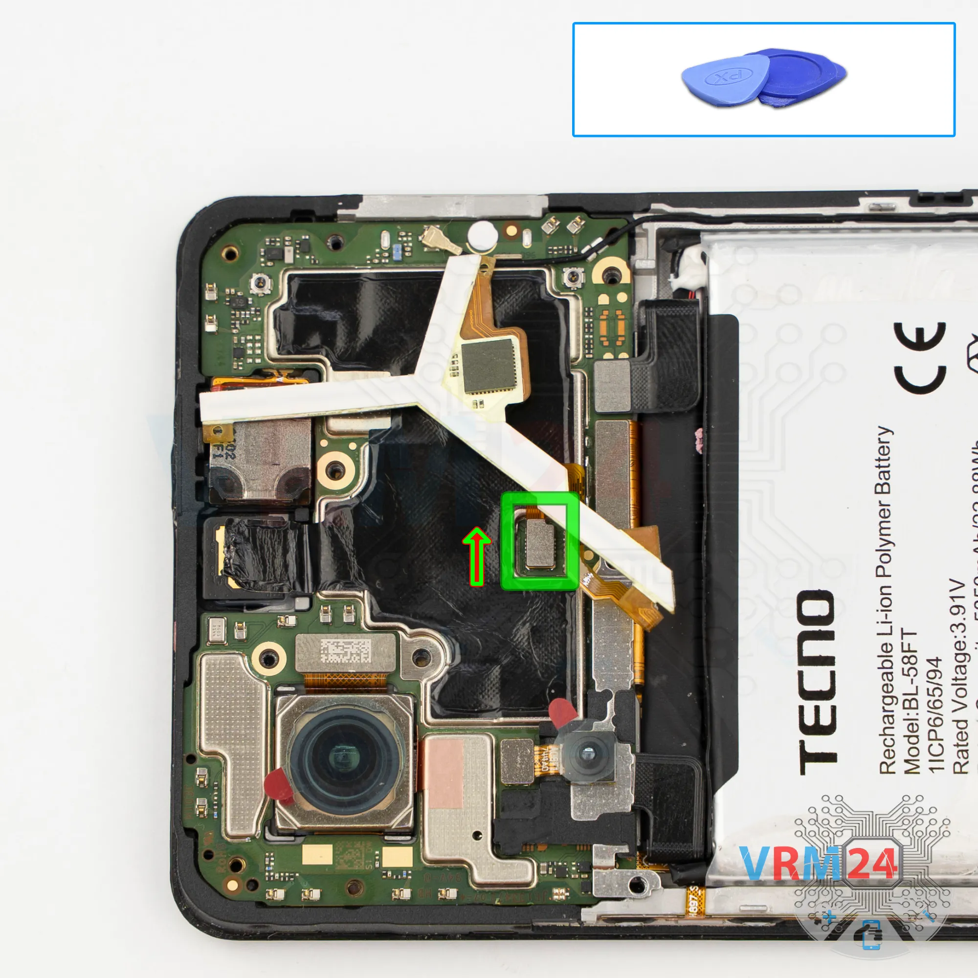
Disconnect the connector
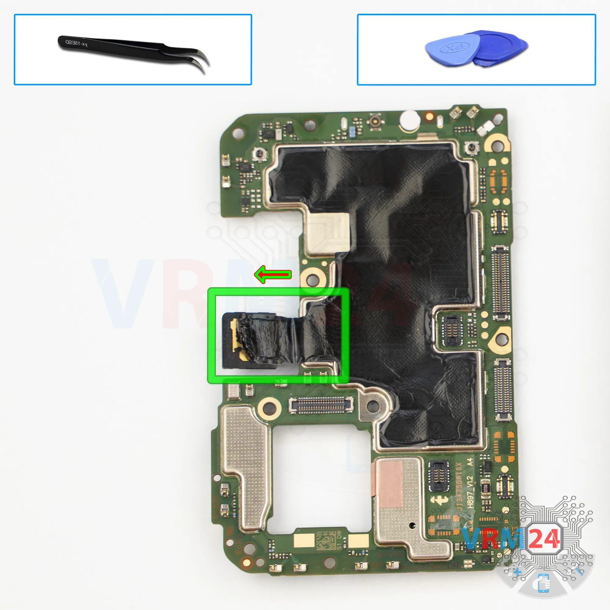
It’s better to disconnect the connector first and remove the flash flex cable.
Step 9.
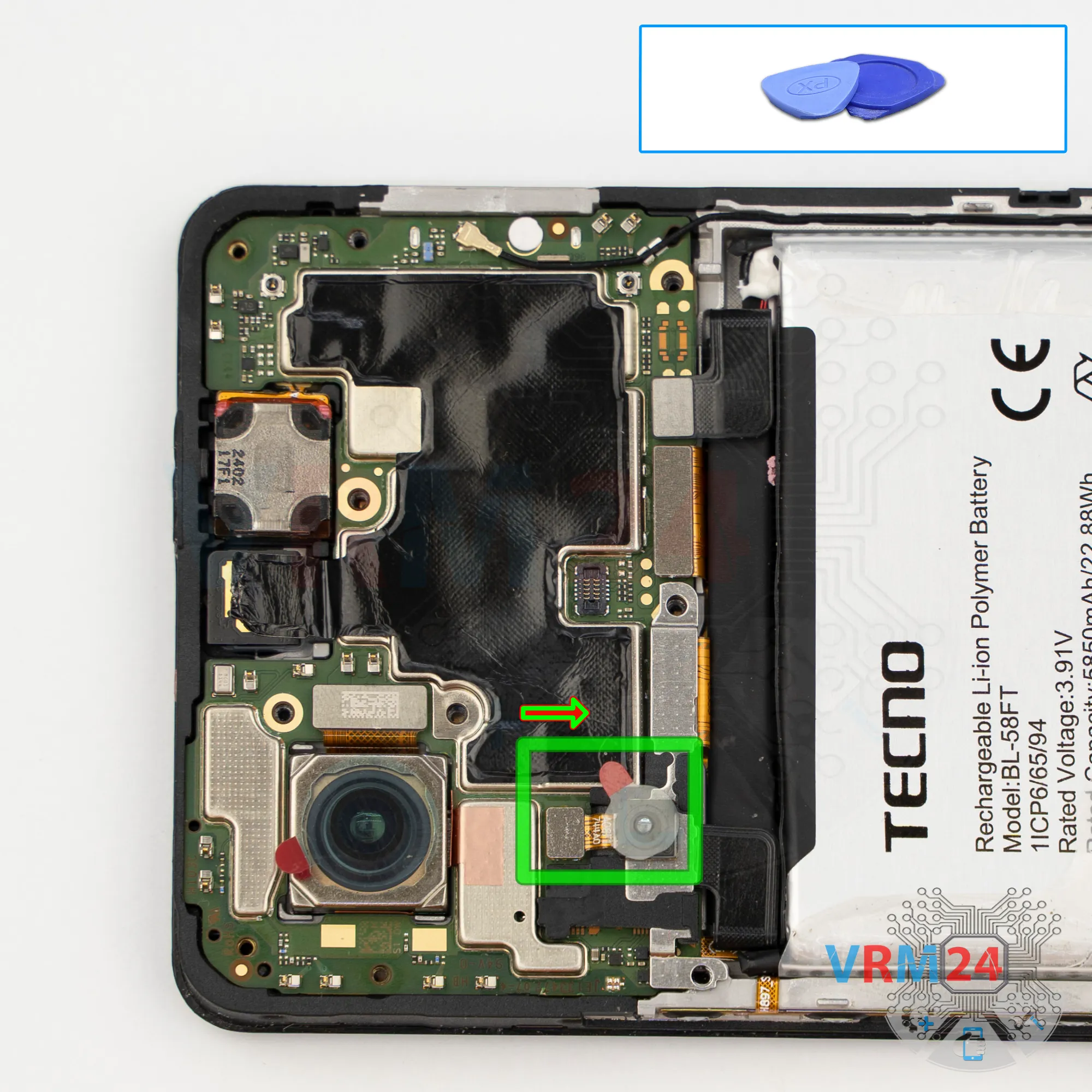
Remove the rear camera
We disconnect the small rear camera.
Step 10.
Remove the bracket
And we disconnect the bracket that holds the connector on which the rear camera was resting.
Step 11.
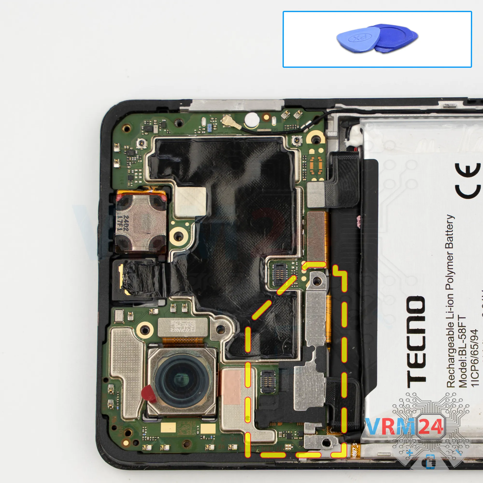
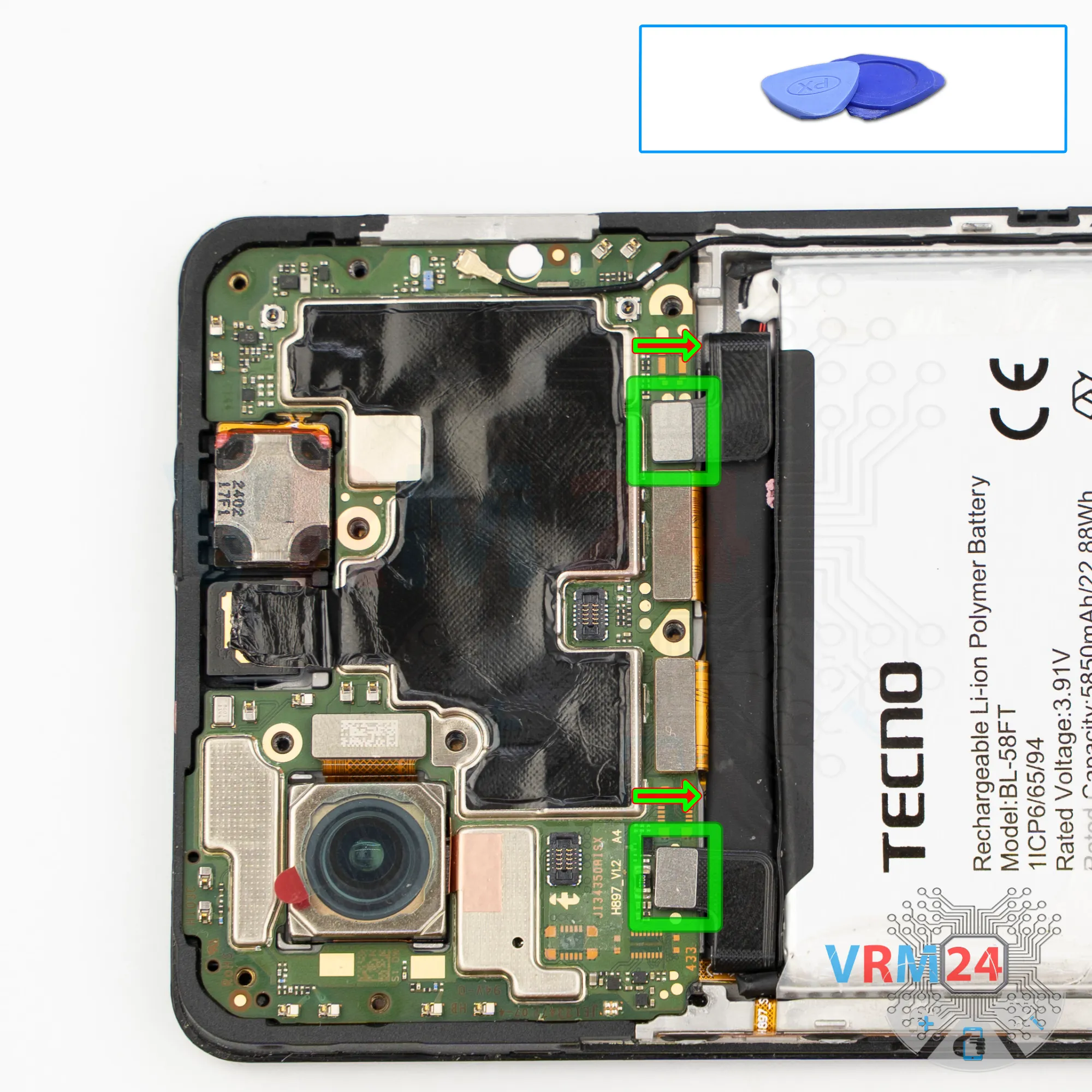
Disconnect the battery connector
Now we can disconnect the both battery connectors.
ℹ️ The Tecno Pova 6 model l17 uses a BL-58FT rechargeable battery with a capacity of 6000 mAh.
Step 12.
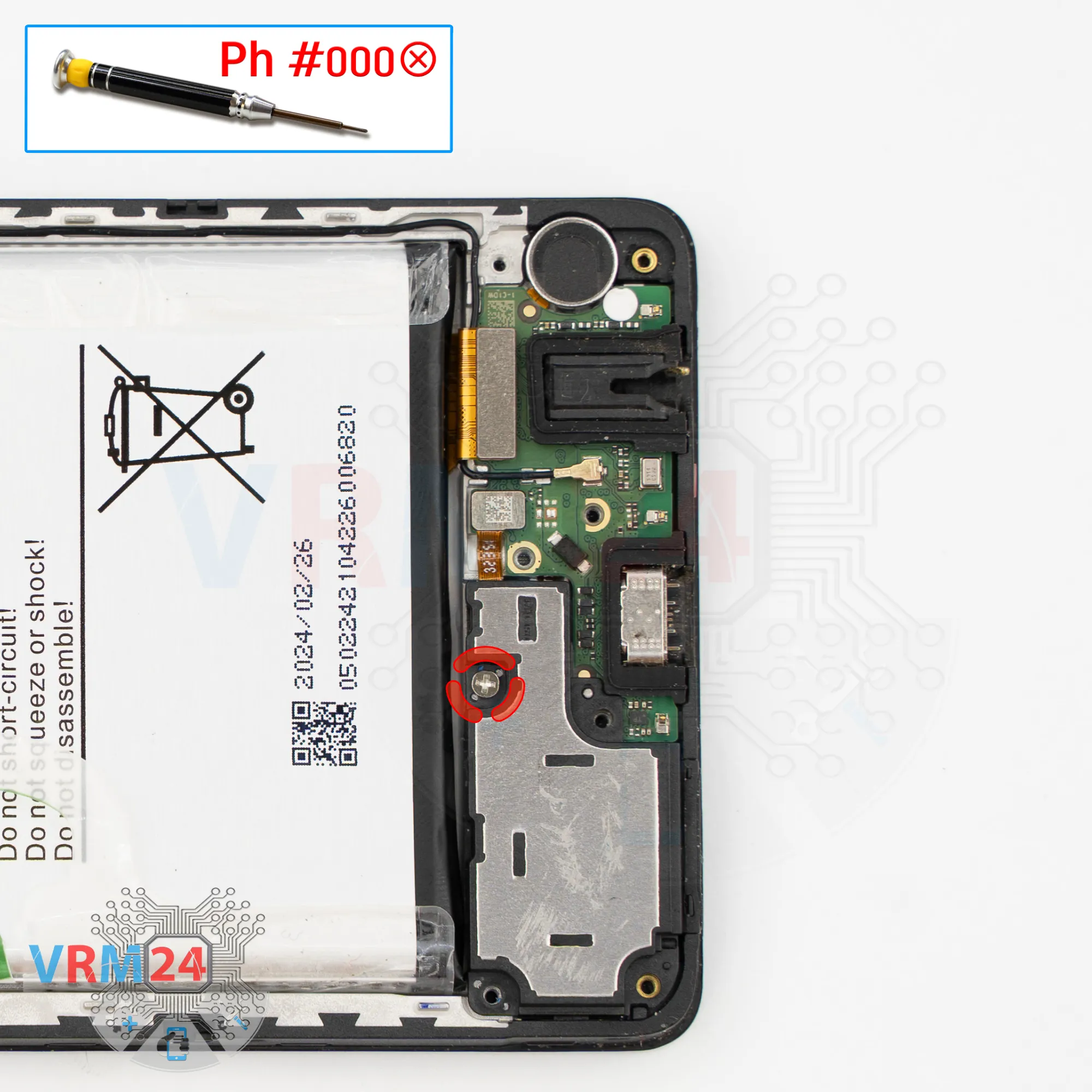
Unscrew one screw
Using a screwdriver Phillips 1.5 mm (PH #000), unscrew the small silver screw securing the loudspeaker.
Step 13.
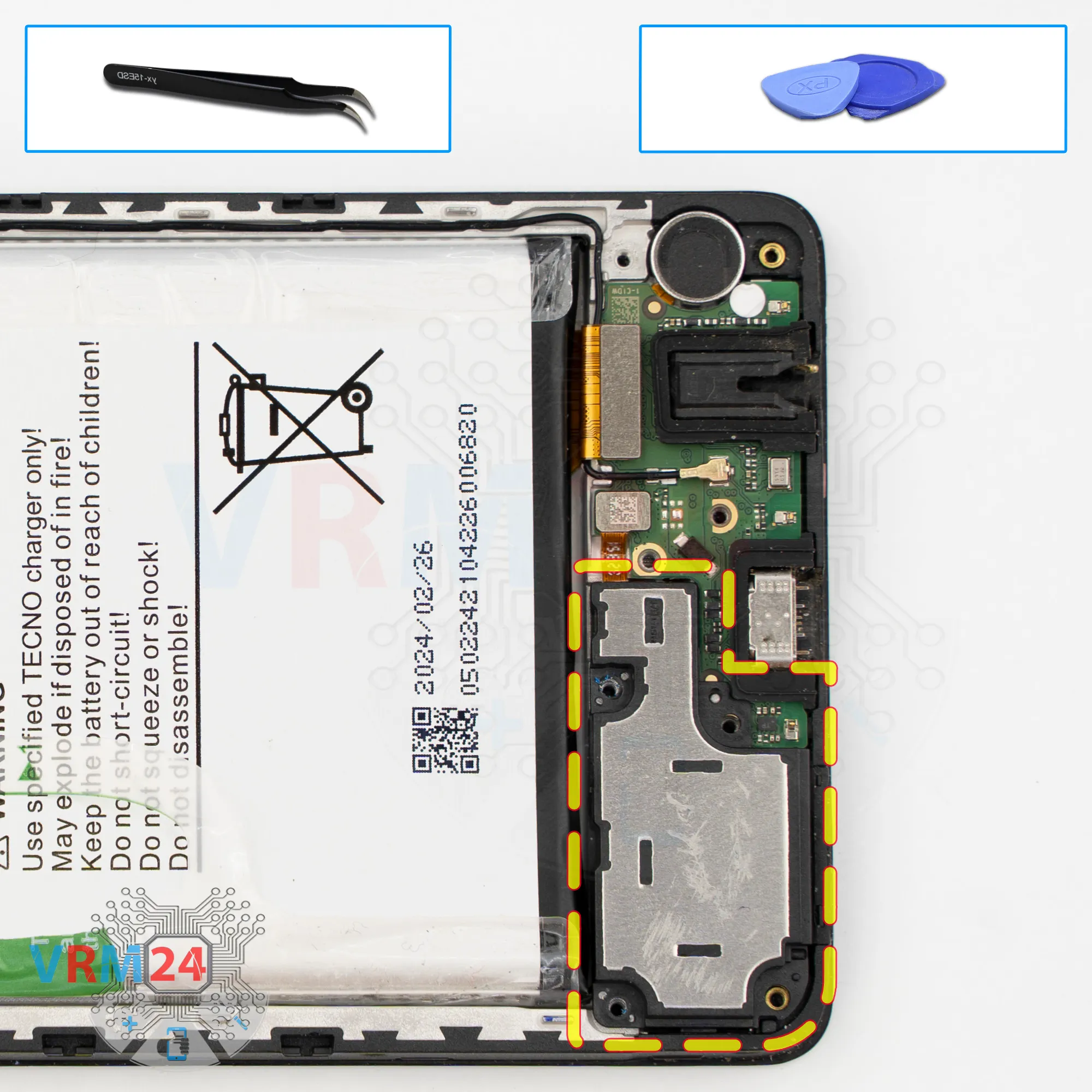
Remove the loudspeaker
And of course, it’s better to remove the cover with the loudspeaker.
Carefully pry it up at the correct spot and detach the cover.
Step 14.
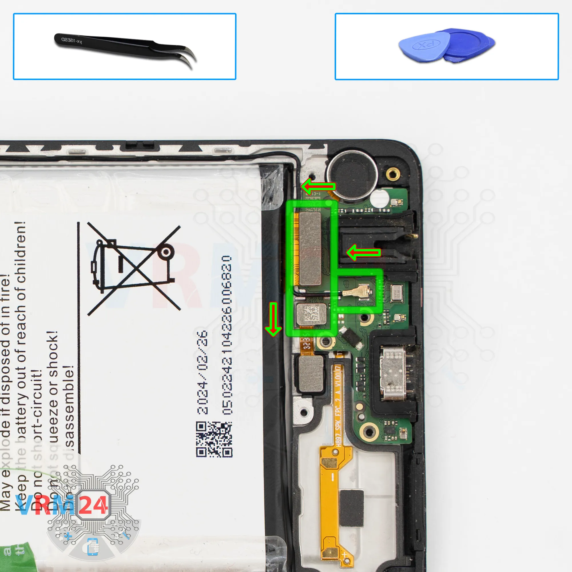
Disconnect the connectors
And we can disconnect the connectors.
We disconnect the fingerprint sensor connector, coaxial cable connector, interconnect flex cable connector.
Step 15.
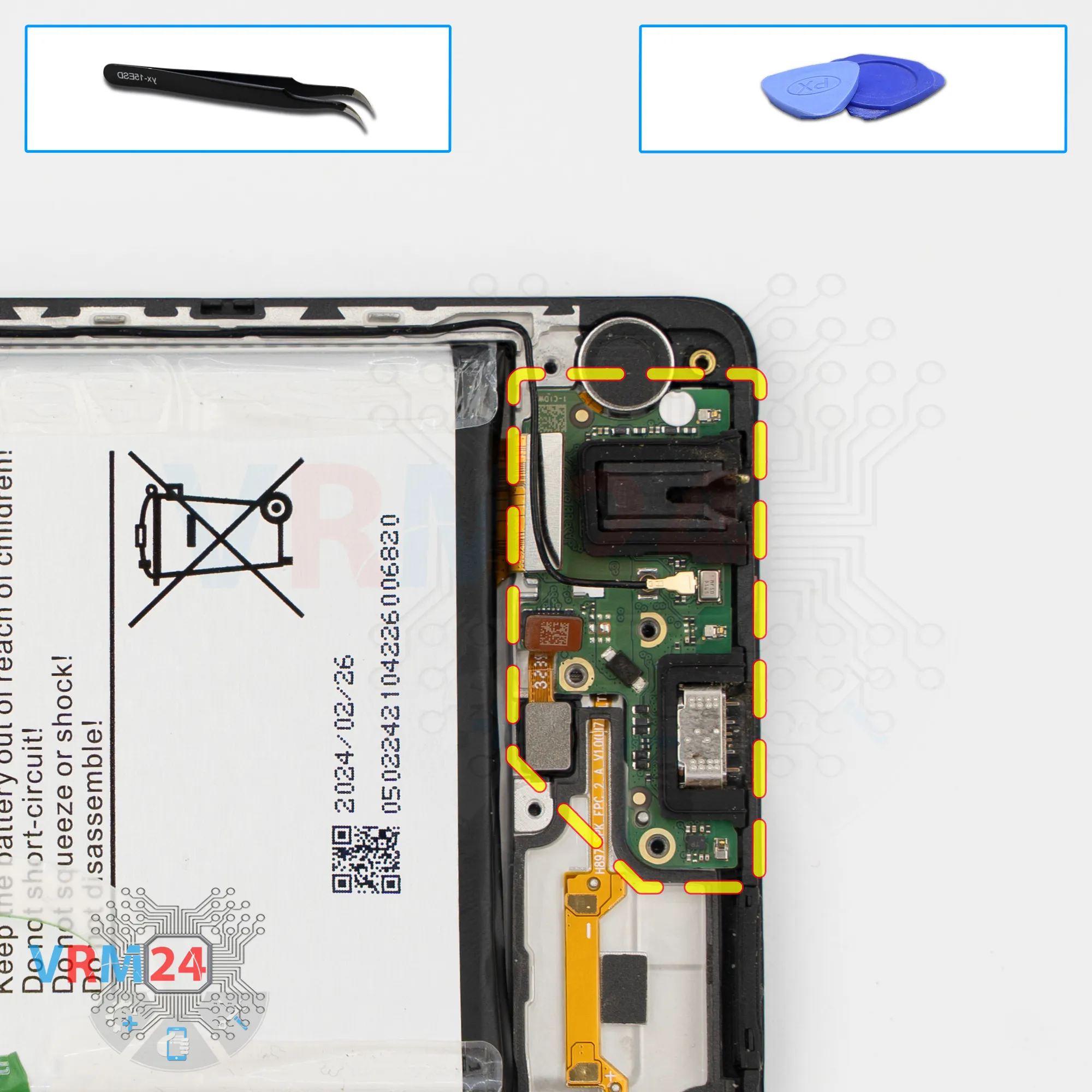
Remove the sub-board
Now we can remove the sub-board.
Again, carefully pry it up by the edge, lift it, and take it out.
On the sub-board, we have the charging port, microphone, headset jack port, and other components on the reverse side.
In the display frame, the fingerprint sensor and the vibration motor remain.
Step 16.
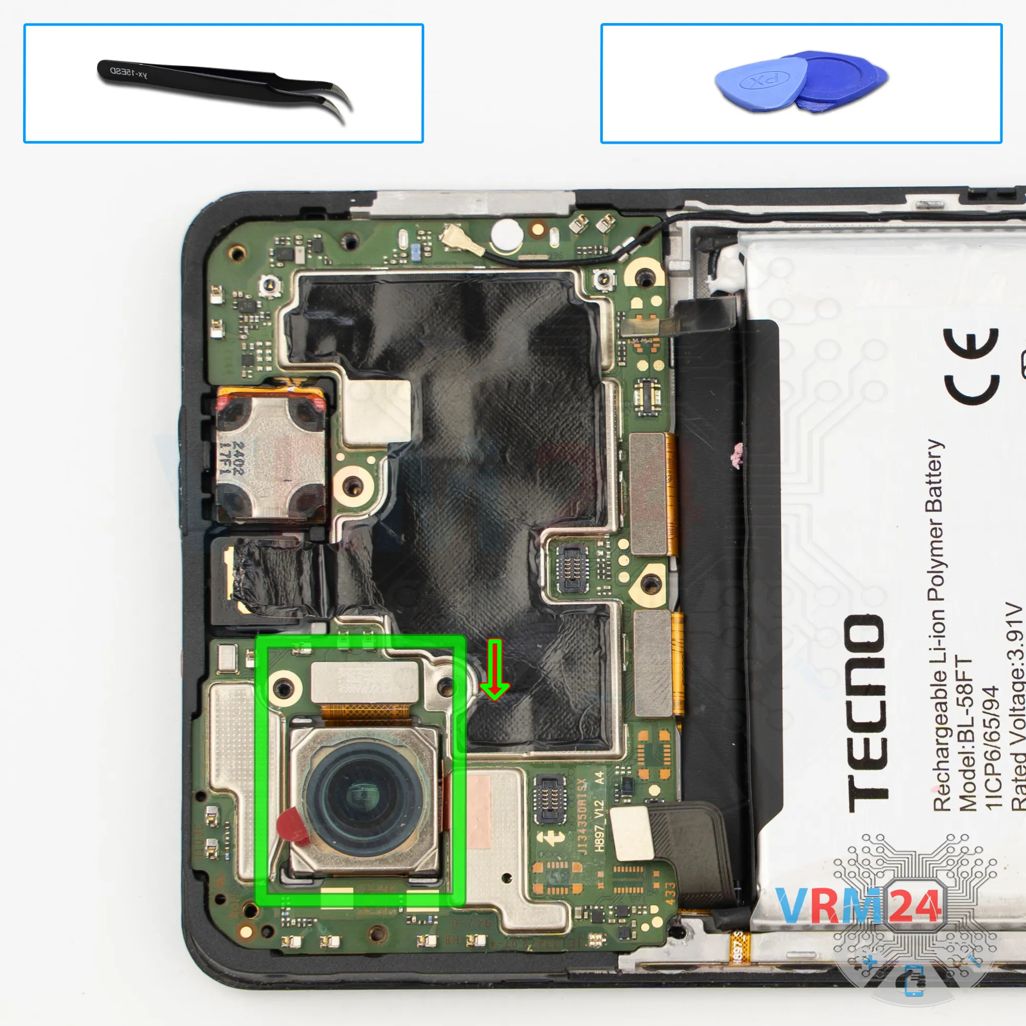
Remove the rear camera
We disconnect the large rear camera and move it aside.
Step 17.
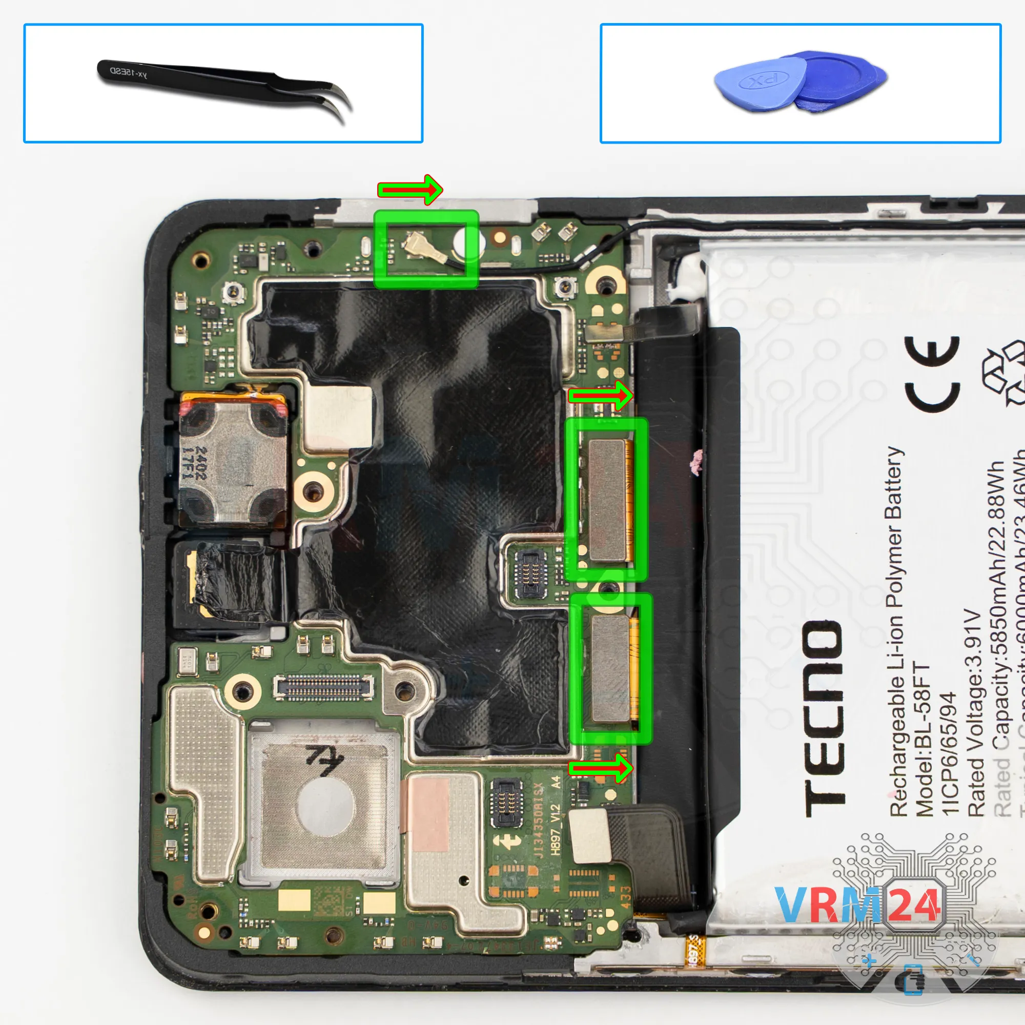
Disconnect the connectors
On the motherboard, we disconnect the coaxial cable connector and release the cable itself from the clips that secure it.
After that, we can disconnect the interconnect flex cable connector and the display flex cable connector.
Step 18.
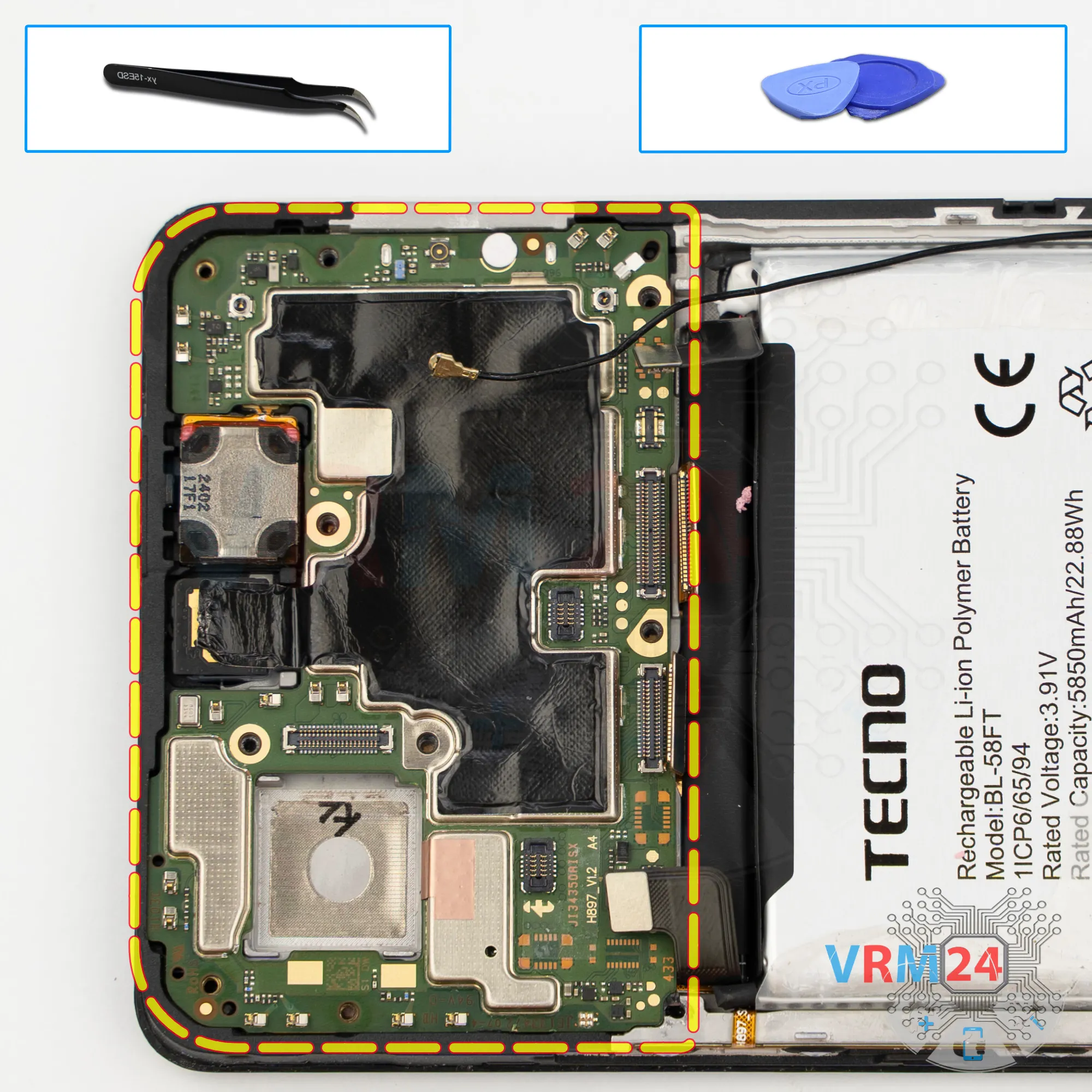
Remove the motherboard
Traditionally for Tecno devices, the heat-dissipating film is glued to the front camera, and the front camera is disconnected after removing the motherboard from the opposite side.
It’s better to peel off the heat-dissipating film so it doesn’t get in the way.
And now we can remove the motherboard.
On the back side, the motherboard may be held in place with thermal paste, so carefully pry it up in the correct spot, lift it, and remove it.
Step 19.
Remove the front camera
Then we flip motherboard over, disconnect the connector and remove the front camera.
It will be a good idea to cover the front camera lens with protective film so that debris doesn’t get on it.
Step 20.
Remove the battery
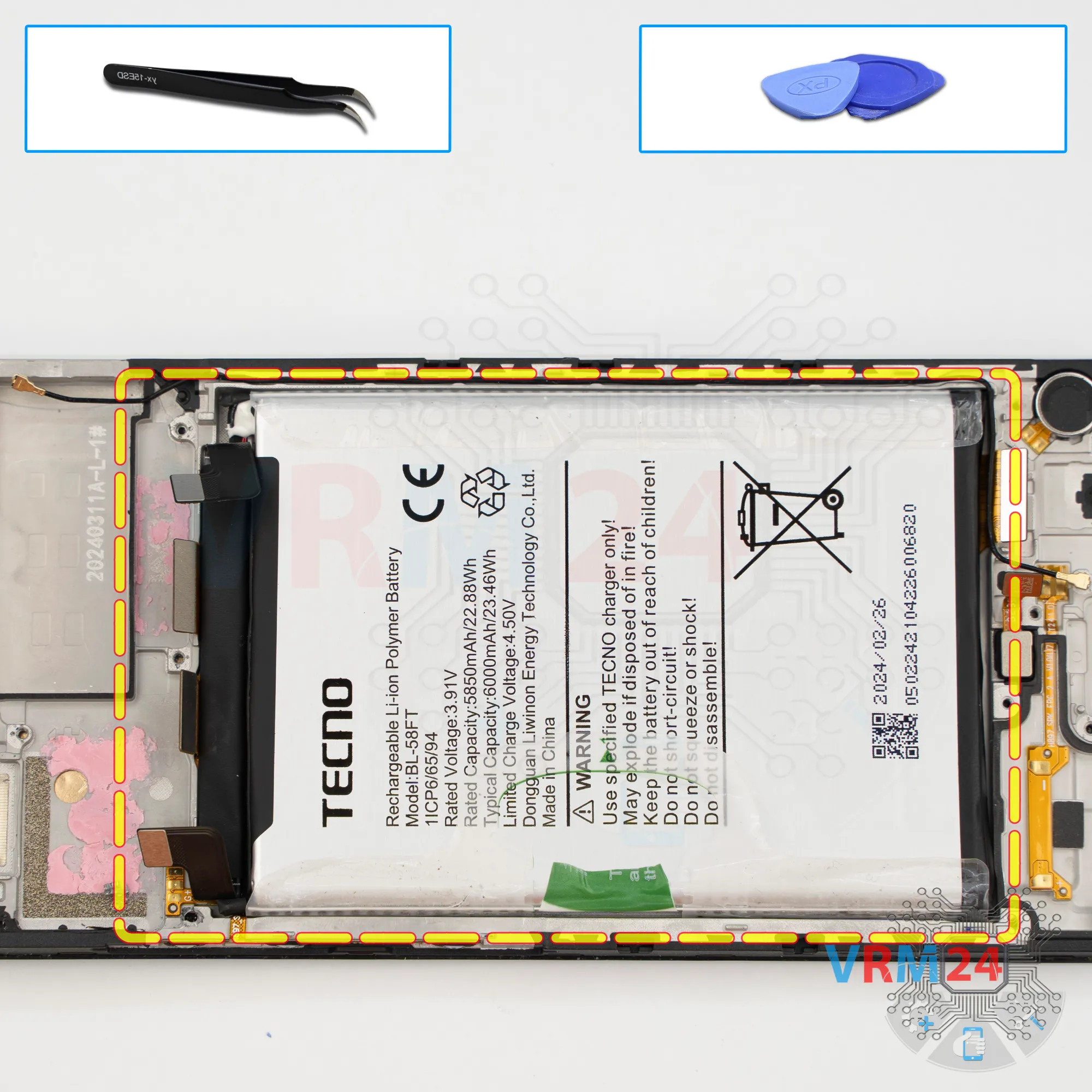
Finally, we move on to removing the battery.
We have a transparent protective layer that needs to be folded back, and a green pull tab that needs to be pulled upward to remove the battery.
So, we fold the transparent layer back as much as possible so it doesn’t hold the battery, and pull the tab upward.
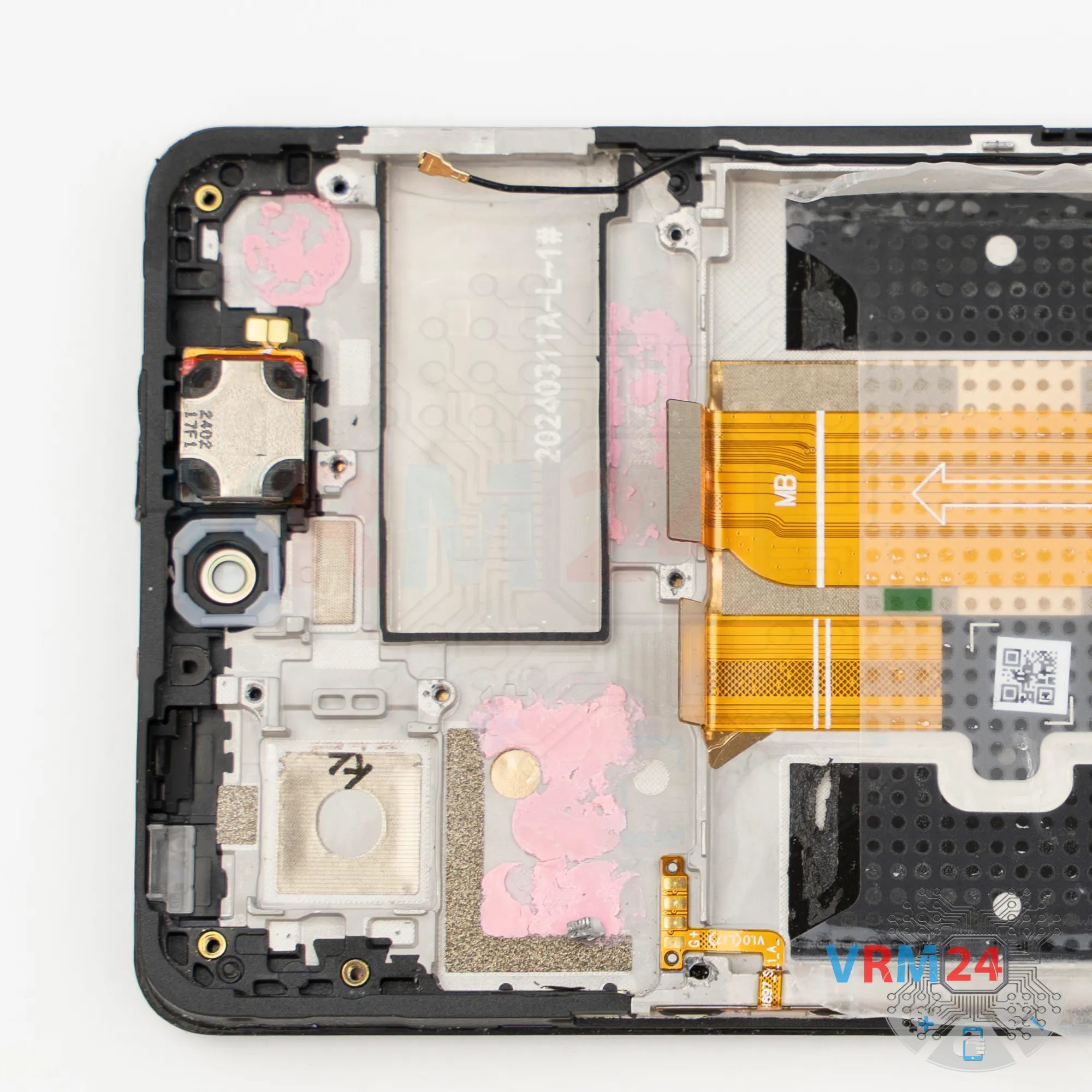
Under the battery there are the interconnect flex cable and the display flex cable.
Step 21.
In the display frame remained
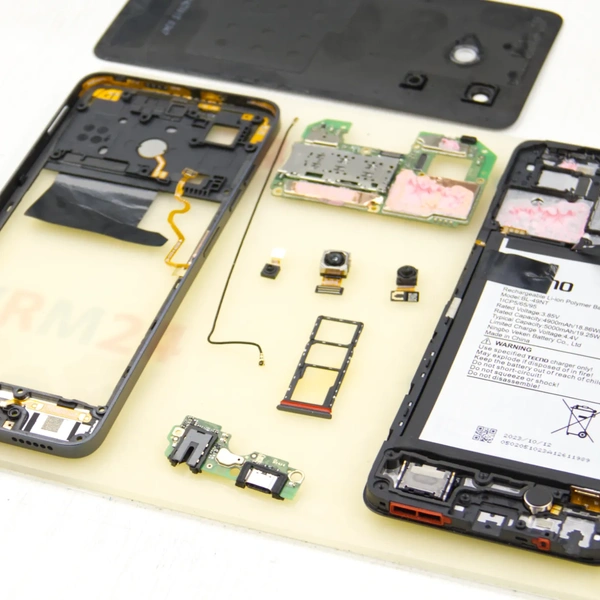
ℹ️ In the display frame remained: the earpiece speaker, vibration motor, side buttons, and cables.

If you have a question, ask us, and we will try to answer in as much detail as possible. If this article was helpful for you, please rate it.

6753
Views
3
Likes
—
Share
0
Questions
Related Instructions
Related Reviews
Related Blog
Top instructions
Check our
Top Tecno instructions most liked by readers
New instructions
Check our
New Tecno brand instructions on vrm24.com