






Recommended tools
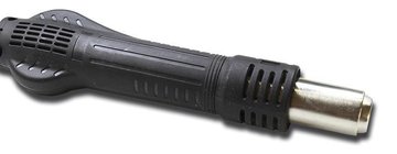
Heat gun
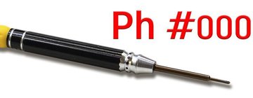
Screwdriver Phillips #000
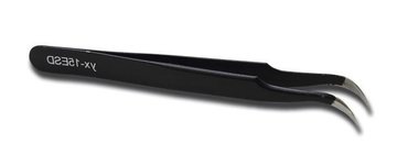
Tweezers
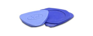
Non-metallic tool
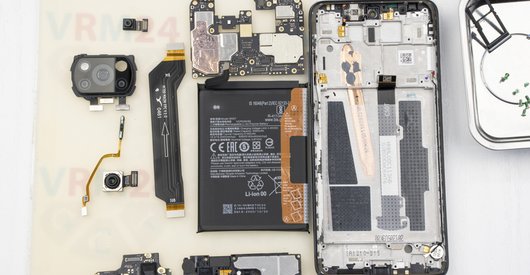
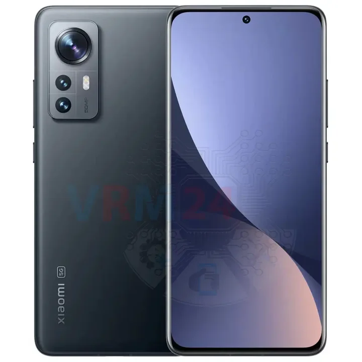
Disassembly/Repair of the mobile device Xiaomi 12X (Xiaomi 12X 2112123AG) with each step description and the required set of tools.
6408
Views
7
Likes
—
Share
0
Questions

Step 1.
Before disassembling!
⚠️ Before disassembling, do not forget to turn your phone off.
Step 2.
Remove the tray
At the very beginning we need to remove the card tray for this we take a special tool, insert it into the right hole and push out the card tray.
⚠️ Please note that the microphone hole is located next to the hole for ejecting the card tray.
Step 3.
Open the back cover
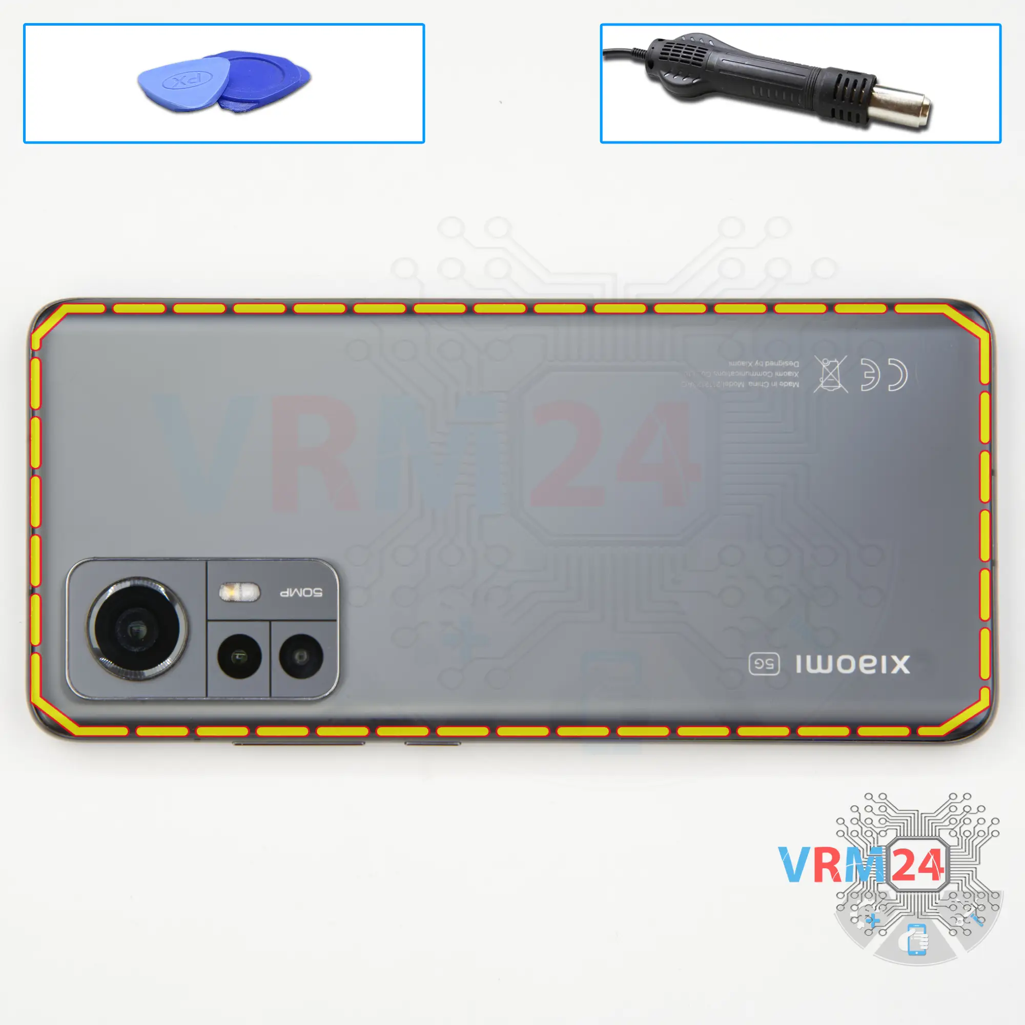
We need to heat the surface of the back cover to about 65-70° C or 160° F. For this we can use a heating mat or a hair dryer.
And after 5-7 minutes we can move on to removing the back cover.
To detach the back cover, we use a plastic film, this is the protective film from the new display or a plastic film from a stationary store.
We insert it into the gap between the middle cover and the back cover and run it along the length of the back cover to detach it.
We always have to be careful around the side buttons and the cameras so as not to damage anything.
Step 4.
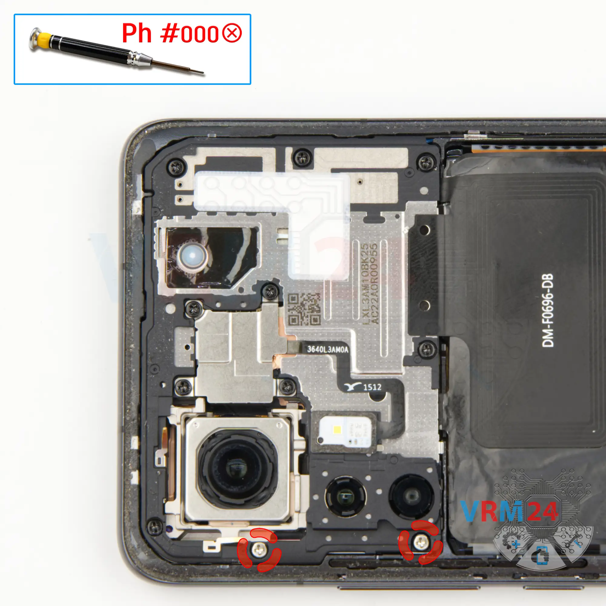
Unscrew the screws
We need to unscrew the two silver long screws at the top, we use a 1.5mm Phillips screwdriver or #000.
⚠️ Remember that the screws are different, some are silver and others are black, so we recommend placing them on a special surface in an easy to remember order for reassembly.
Step 5.
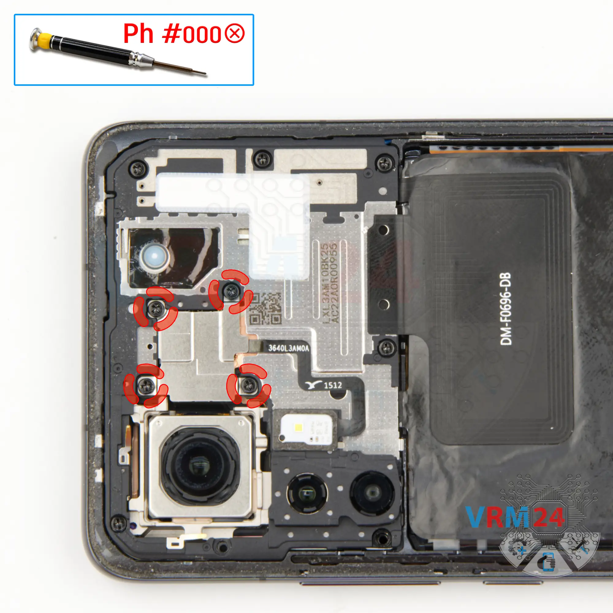
Unscrew the screws
Using a screwdriver Phillips 1.5 mm (PH #000), unscrew the four screws holding the bracket.
Step 6.
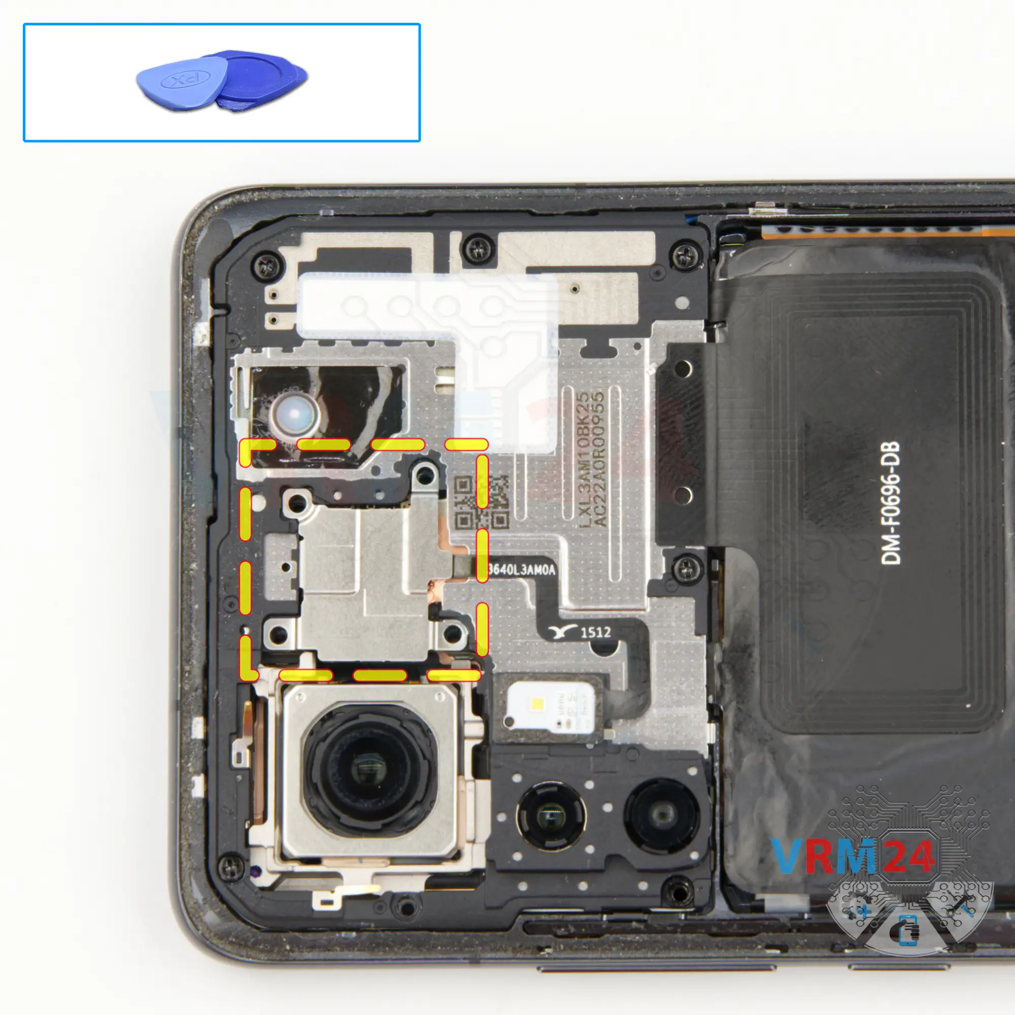
Remove the bracket
Moving on to detach the small bracket in the middle hiding the connector.
Step 7.
Disconnect the connector
We removed the bracket and then we need to disconnect the connector to the flashlight.
And only after that we can detach the cover that hides the motherboard.
Step 8.
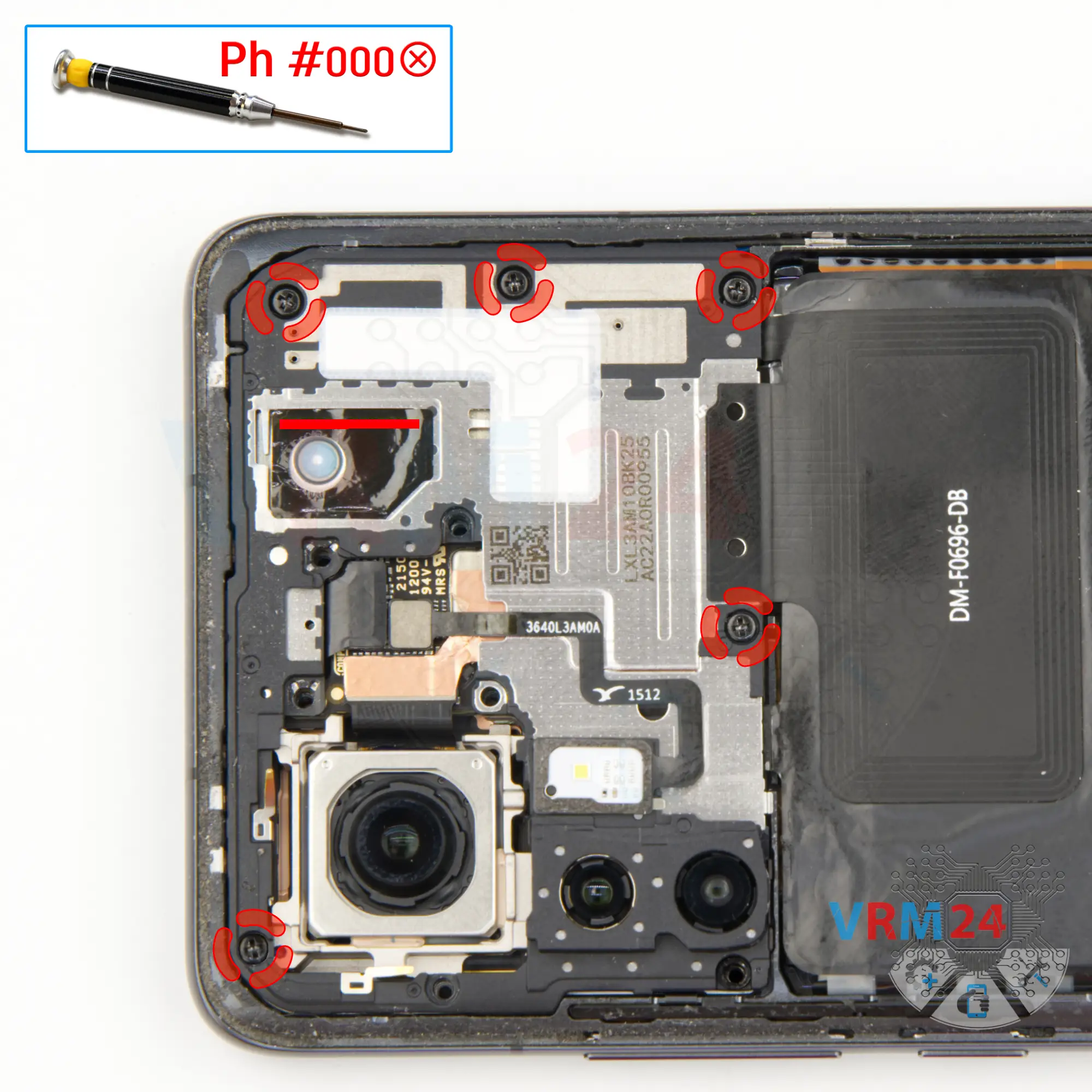
Unscrew the screws
Using a screwdriver Phillips 1.5 mm (PH #000), unscrew the last five screws.
Step 9.
Open the cover
Pry over the edges. Move an opening tool along the edge detach the clips and remove the cover with an NFC, transmission lines and pads for antenna.
ℹ️ Try to lift the cover by the edges and not push anything between them to not accidentally touch or short-circuit anything on the circuit board.
⚠️ It is crucial while reassembling, checking the spring contacts on the board, and the contact pads on the cover match and touch. Otherwise, the signal loss or signal may be quite weak.
Step 10.
Disconnect the battery connector
Disconnect the battery connectors as soon as you can. Use a non-metallic or plastic tool to avoid any damage.
ℹ️ The Xiaomi 12X 2112123AG model has a battery BP46 with a capacity of 4500 mAh (also known as a rechargeable battery).
Step 11.
Unscrew the screws
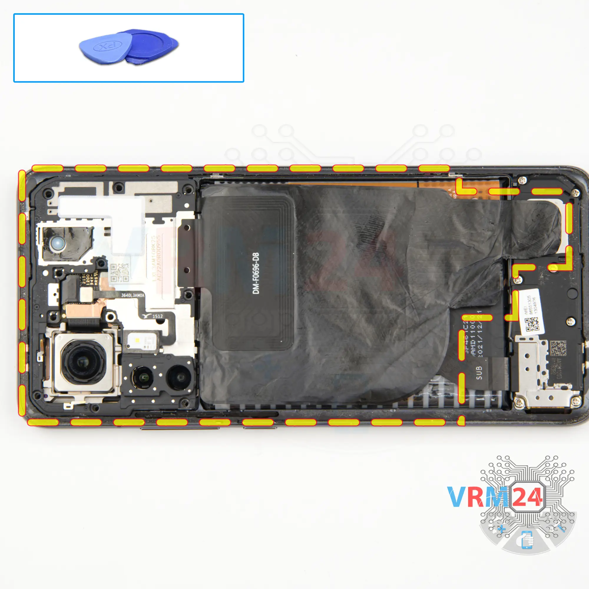
Well, we move on to unscrewing the screws in the bottom part.
The screwdriver is the same Phillips screwdriver and the screws at the bottom look the same, but it is still better to place them on a special surface in a certain order for reassembly, just in case.
⚠️ Sometime the screws can get stuck we use tweezers to remove them.
Step 12.
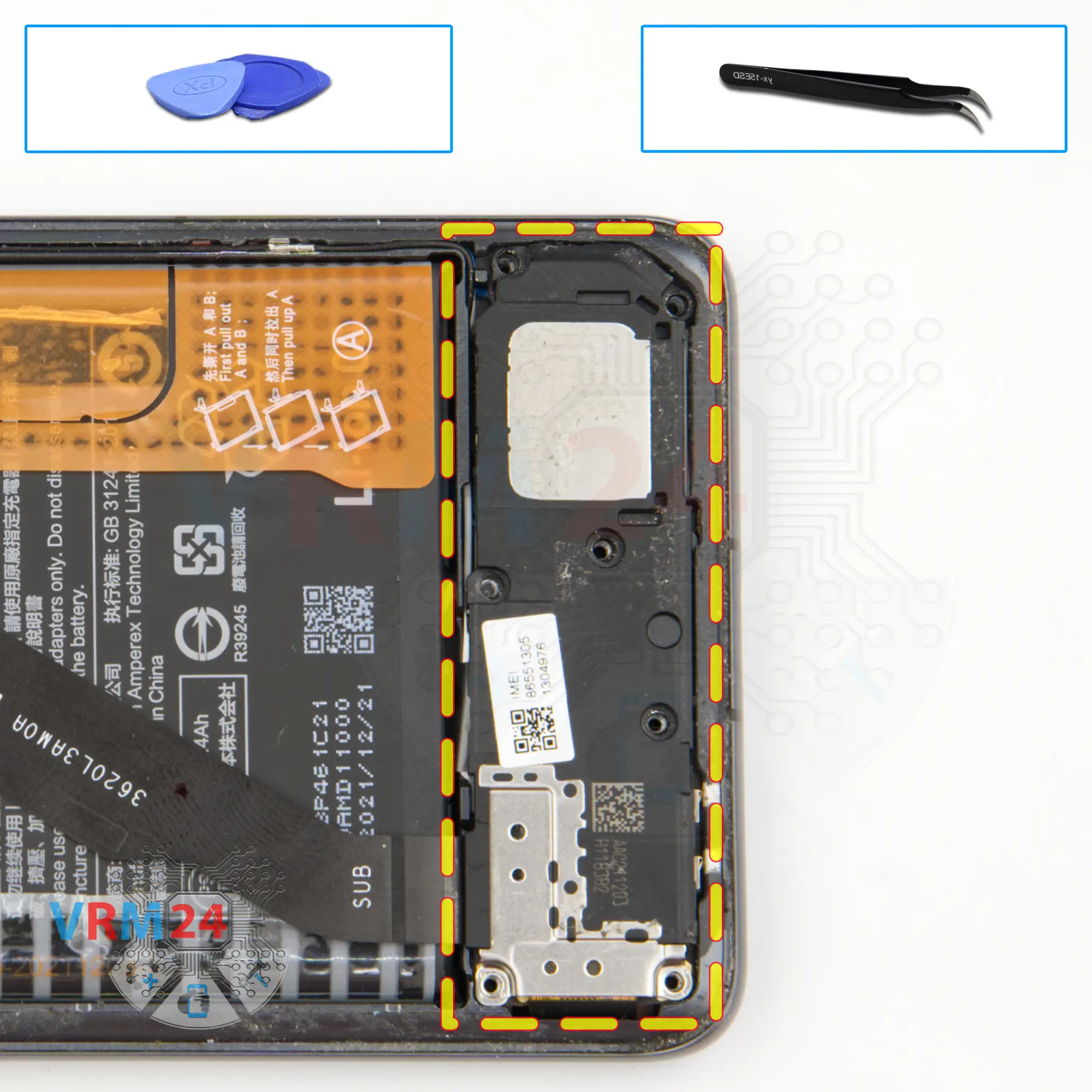
Remove the loudspeaker
We find the right place to hook and detach the cover with the loudspeaker.
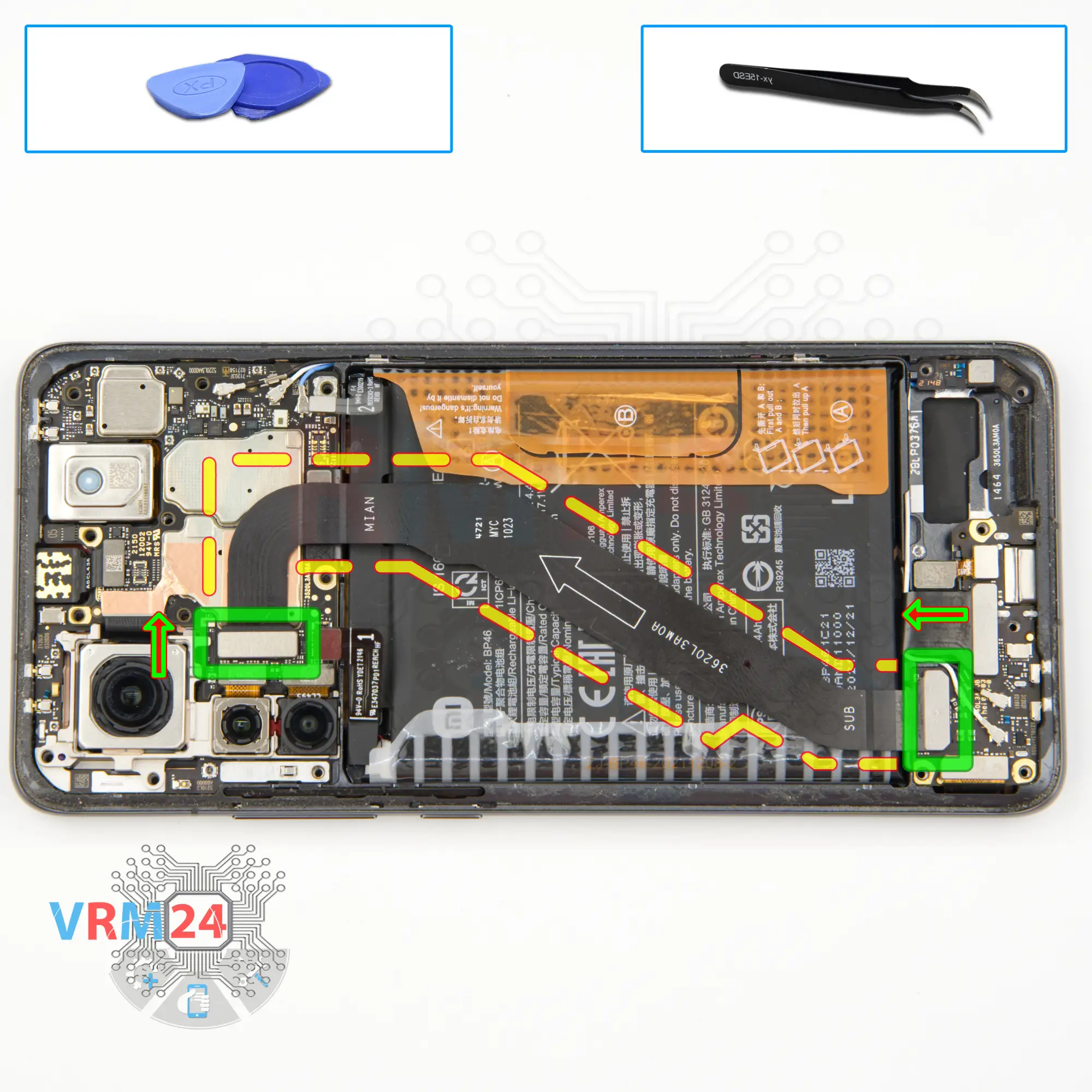
Step 13.
Remove the interconnect cable
After that, we disconnect the connectors on both boards and remove the inter-board cable.
ℹ️ An arrow on the FFC cable (flexible flat cable) indicates its correct position.
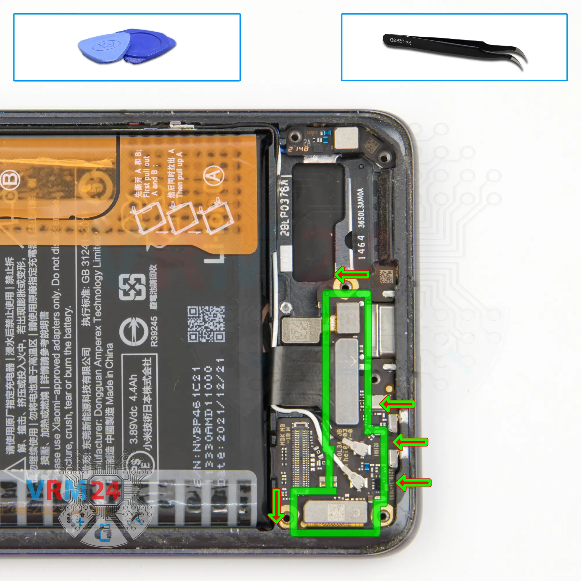
Step 14.
Disconnect the connectors
We move on to disconnecting the connectors on the sub-board.
We disconnect the inter-board cable connector, the connector for the fingerprint sensor. We disconnect the connectors of two coaxial cables and release the cables themselves from the clips fixing them on the sub-board.
And we need to disconnect one more connector to the display.
Step 15.
Remove the sub-board
Now we can detach the sub-board. Find the right place where we can hook and lift the sub-board, make sure that there is nothing in the way and remove the sub-board.
On the sub-board we have the microphone, charging port and card connector on the back side.
Step 16.
Disconnect the connector
We detach the connector on the small antenna board.
Step 17.
Remove the small board
We lift up and turn the small board over.
On the back side we have a coaxial cable connector that we need to disconnect and release the cable itself to detach the board.
Step 18.
Remove the cameras
Then we proceed to disconnect the rear camera connectors. We carefully disconnect the connectors and remove the assembly of three rear cameras.
After that, we can detach the front camera.
Step 19.
Disconnect the connectors
We disconnect the inter-board cable connector and disconnect the three connectors of the three coaxial cables and release the cables themselves.
Step 20.
Remove the motherboard
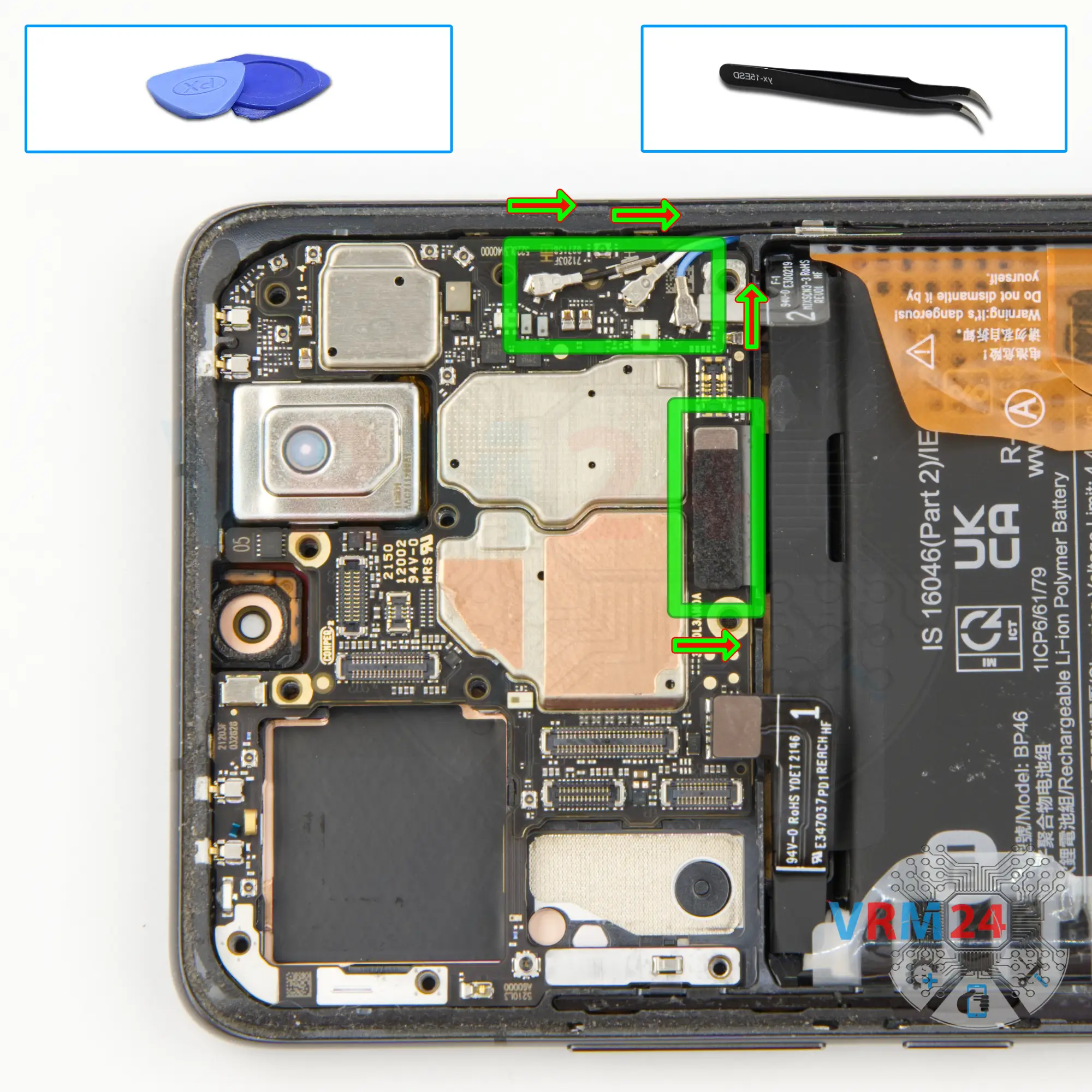
Once that's done, we can carefully detach the motherboard.
Find the right place to hook the motherboard, lift it, gently rock the board back and forth and try to remove it.
⚠️ Do not bend the circuit board when removing it or push tools under it. Unbeknownst to yourself, you can damage components or cables from the inside.
Step 21.
Remove the battery
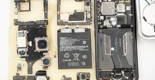
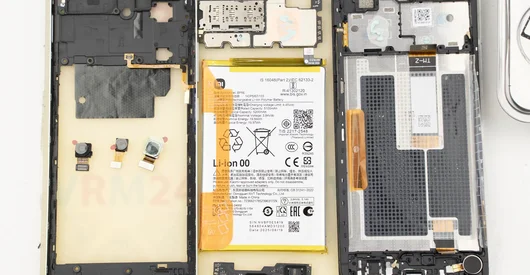
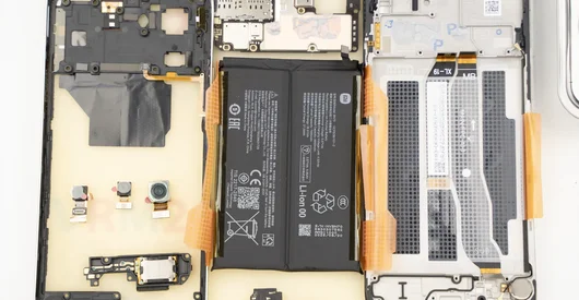
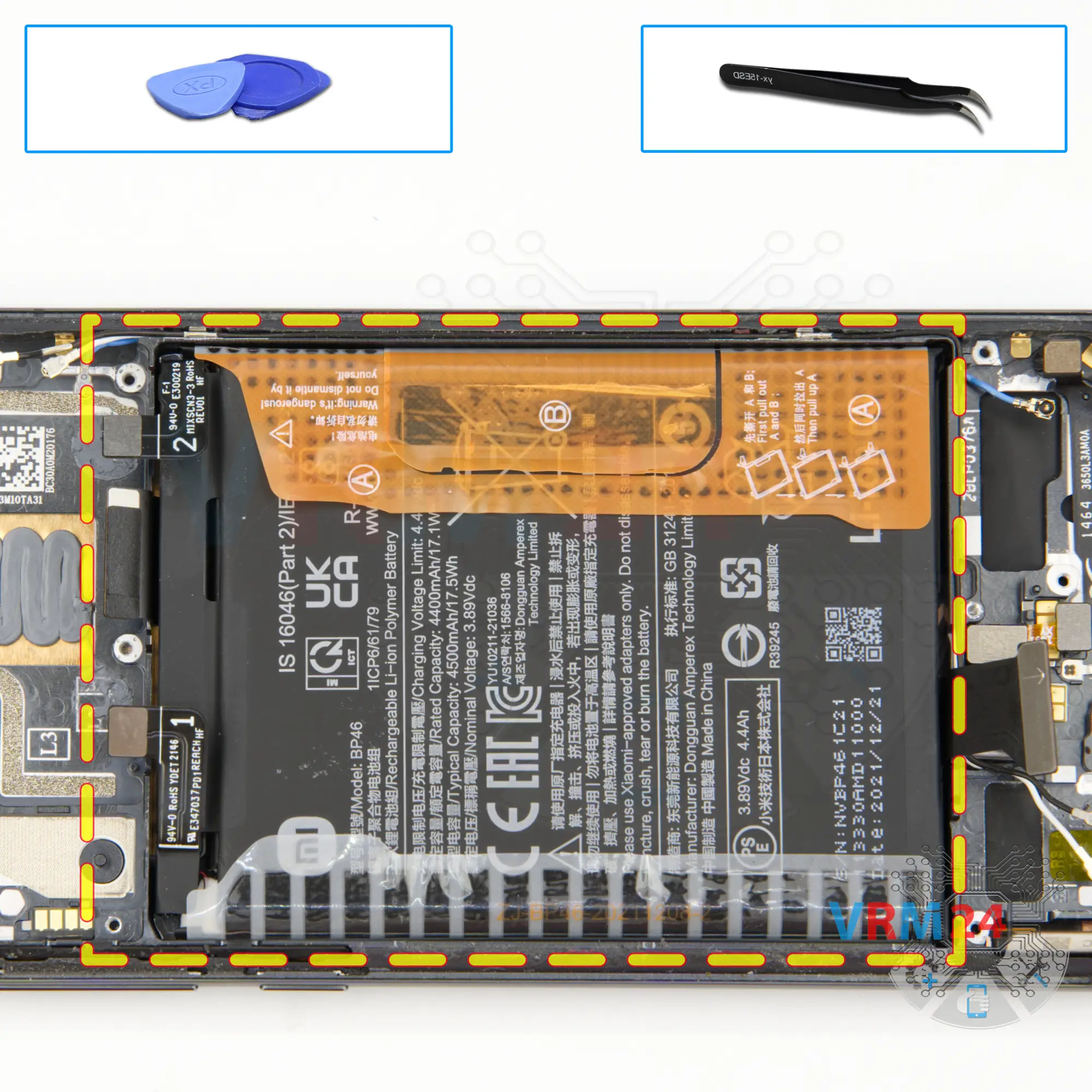
Finally, we move on to detaching the battery.
Unwrap the brown tabs with the letters A and B. Unwrap the transparent covering on the other side of the battery, which also holds the battery in place. And read the description on the wide A tab.
So, as we can understand from the description, we have to unwrap both tabs, and gently pull the wide A tab upwards. Gently pull upwards and detach the battery.
After we removed the battery we can see under it there is a transparent coating that protects the inter-board cable.
Step 22.
In the display frame remained
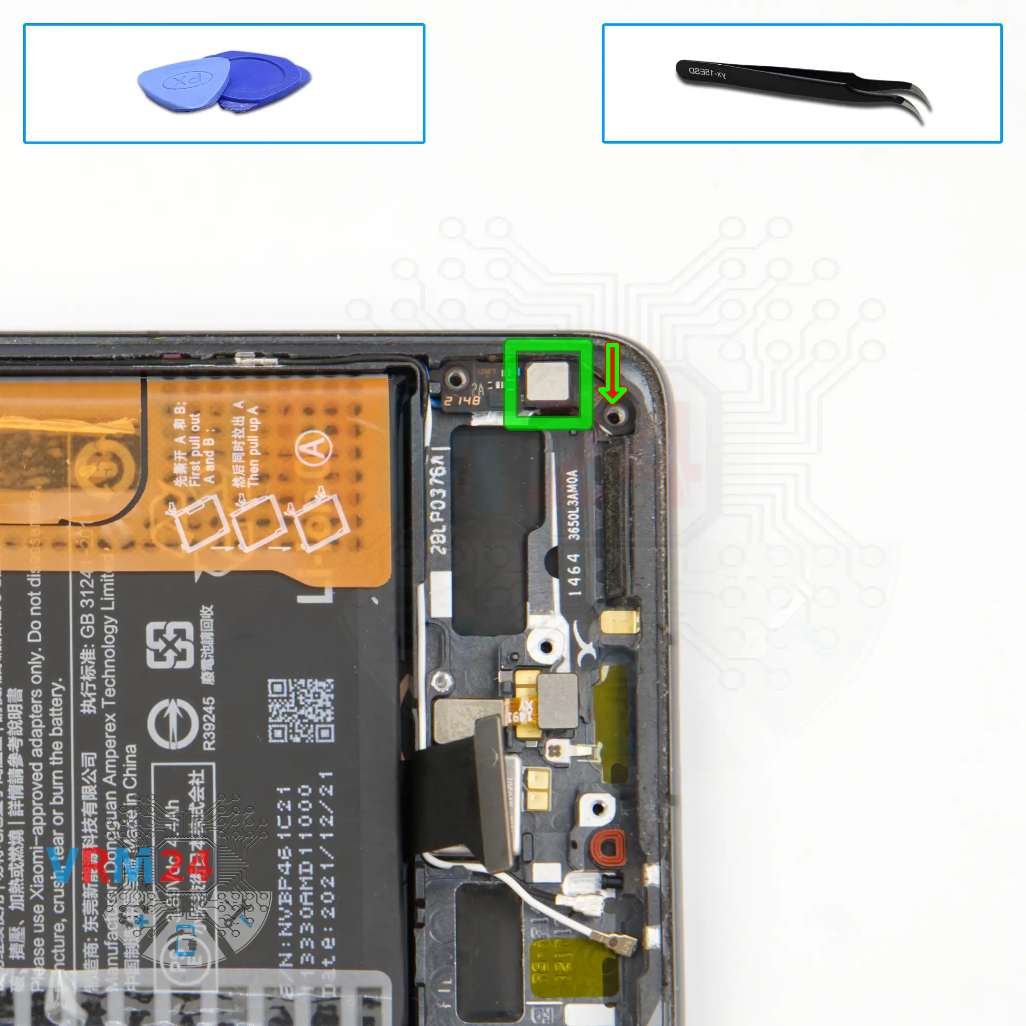
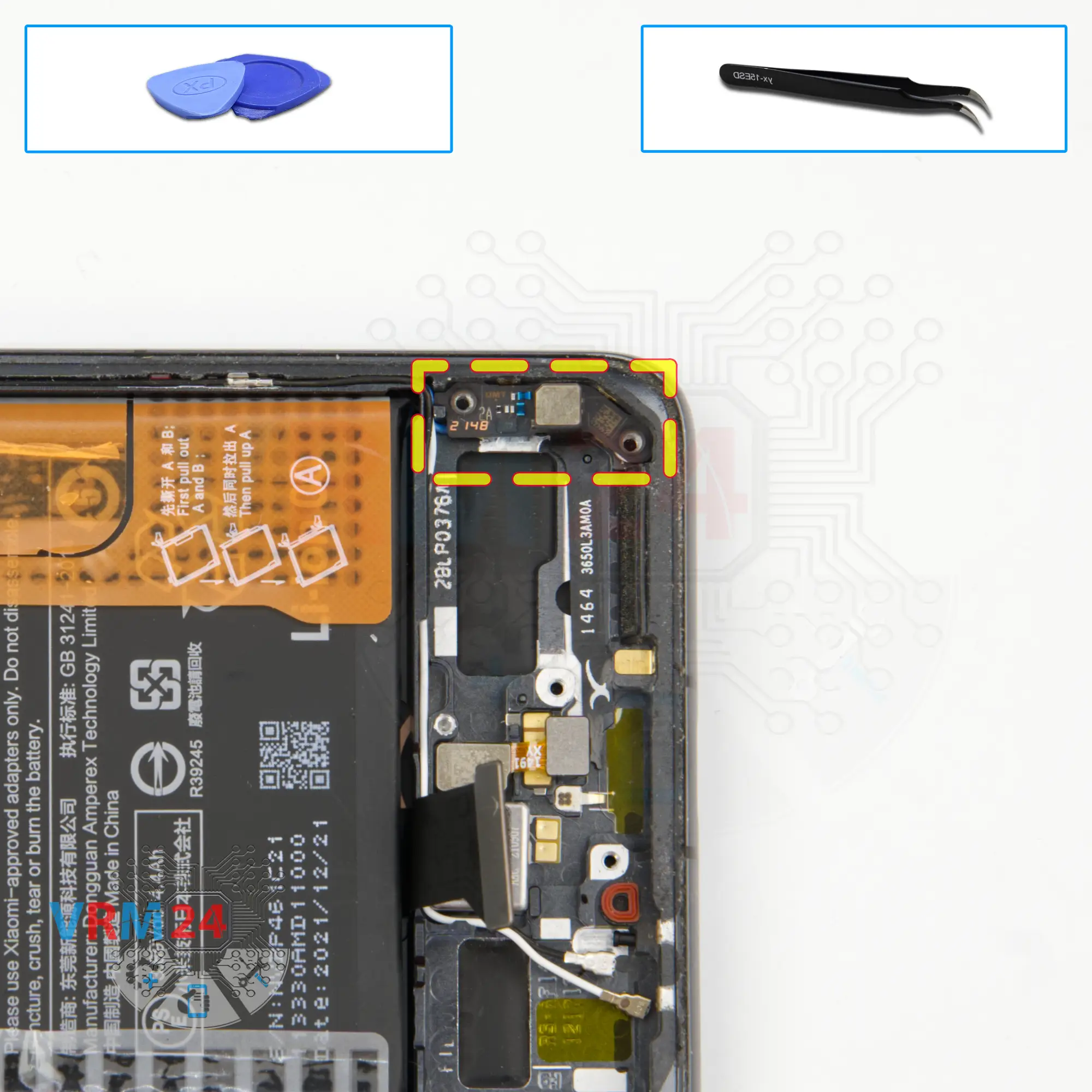
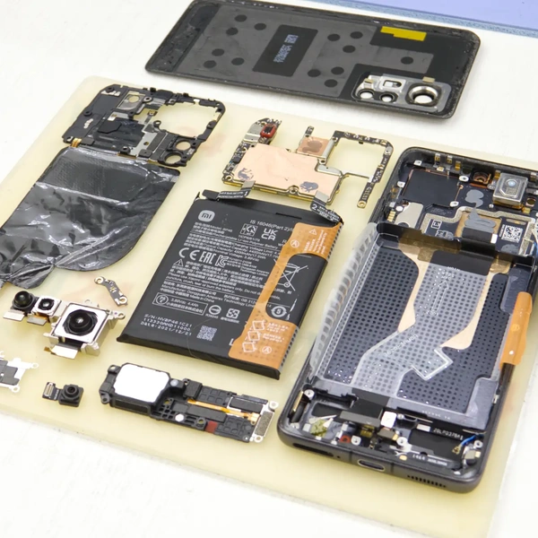
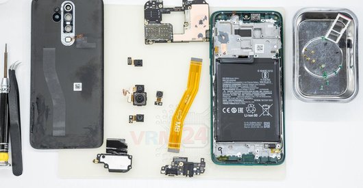
ℹ️ In the display frame remained: the earpiece speaker, fingerprint sensor, vibration motor, coaxial cables.

If you have a question, ask us, and we will try to answer in as much detail as possible. If this article was helpful for you, please rate it.

6408
Views
7
Likes
—
Share
0
Questions
Related Instructions
Related Reviews
Related Blog
Top instructions
Check our
Top Xiaomi instructions most liked by readers
New instructions
Check our
New Xiaomi brand instructions on vrm24.com