


Recommended tools
Screwdriver Five-point P0.8 mm

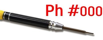
Screwdriver Phillips #000
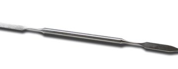
Opening tool / Spudger
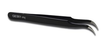
Tweezers
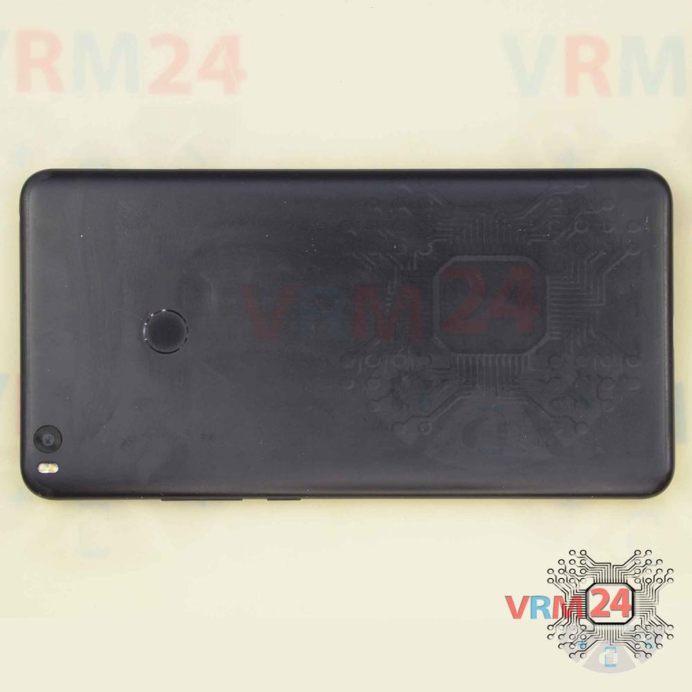
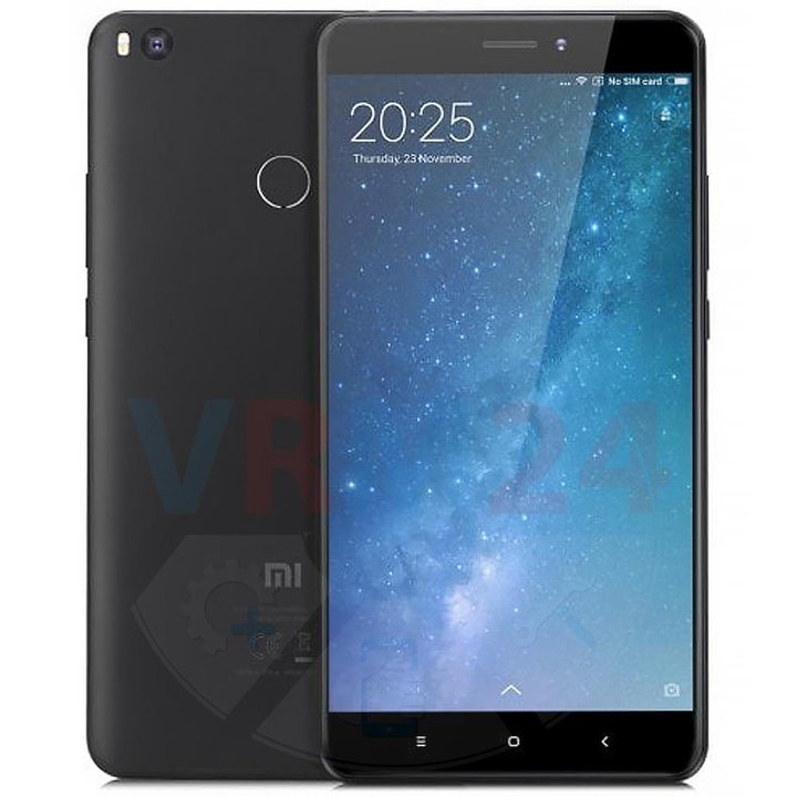
Disassembly/Repair of the mobile device Xiaomi Mi Max 2 (Xiaomi Mi Max 2 MDE40) with each step description and the required set of tools.
10979
Views
5
Likes
—
Share
0
Questions

Step 1.
Before disassembling!
⚠ Before disassembling, do not forget to turn your phone off.
Step 2.
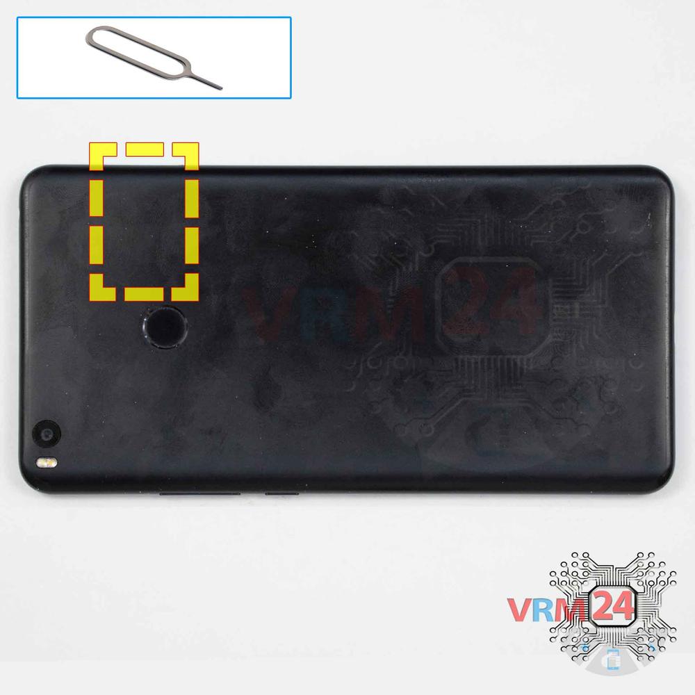
Remove the tray
Use the Key tool (aka Needle) or Paperclip. Push the tip all the way into the hole until the tray ejects, and then pull the tray of SIM and Memory card (Micro SD) out.
⚠ Pay attention! The tool must be inserted into a hole on the edge of the phone's housing. Do not press too hard. It may break the tray eject mechanism.
Step 3.
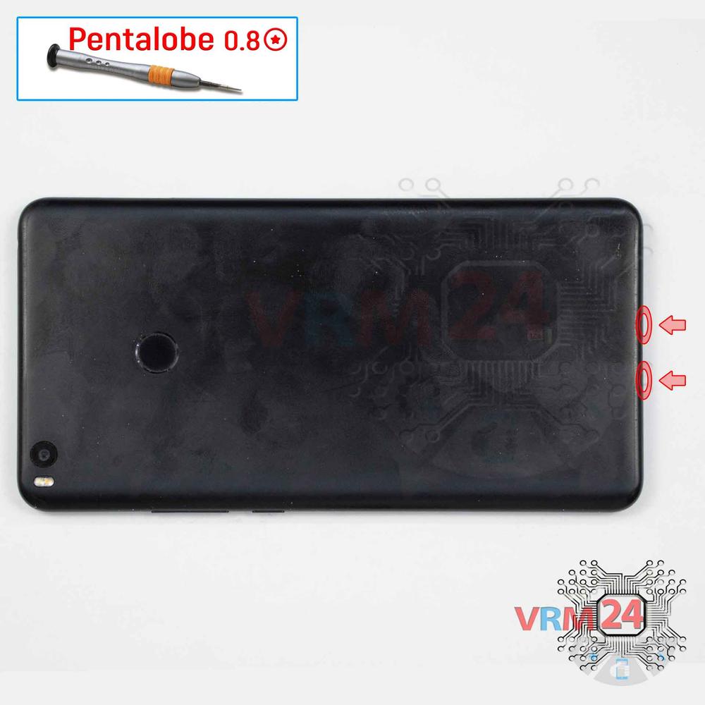
Unscrew the screws
Using a screwdriver (precision star-shaped 0.8 mm aka Pentalobe), unscrew/drive 2 screws out at the end of the phone.
Step 4.
Open the back cover
Using a spudger or a plastic pick, carefully, around the edge, detach the back cover clips, and remove it.
Do not insert the tool deeply or bend it. Otherwise, the housing may be tampered with or damaged.
⚠ Be careful when opening the cover from the volume and power buttons side. Thin cable and fragile buttons are straightforward to damage.
⚠ Pay attention to the fingerprint sensor glued to the back cover from the inside.
Step 5.
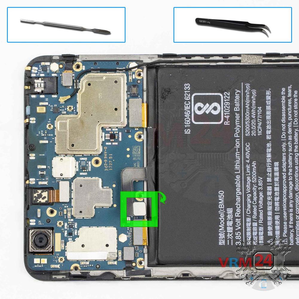
Disconnect the connector
Disconnect the fingerprint sensor connector and remove the back cover.
Step 6.
Unscrew the screws
Using a screwdriver (Phillips 1.5 mm PH000), unscrew 8 screws.
Step 7.
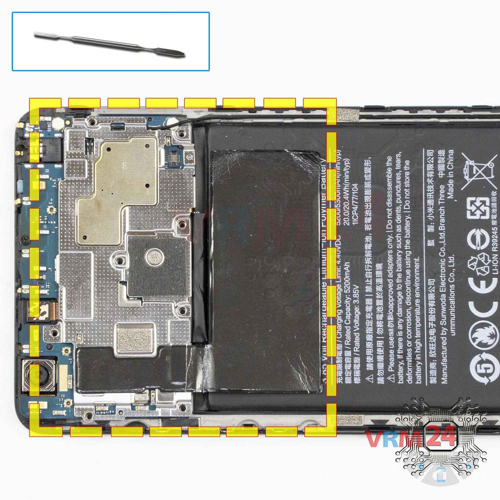
Open the cover
Remove the cover hiding the motherboard.
Step 8.
Disconnect the battery connector
Disconnect the battery connector as soon as possible.
ℹ️ The Xiaomi Mi Max 2 MDE40 model has a battery BM50 with 5200 mAh capacity (aka rechargeable battery).
⚠ It is highly recommended to disconnect the connector to avoid possible short circuits during disassembly.
Also, try not to use a metal tool to disconnect the rechargeable battery connector or do it carefully.
Step 9.
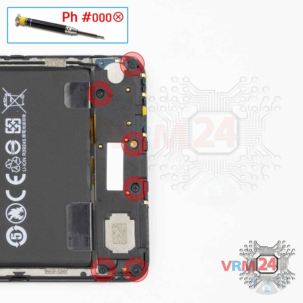
Unscrew the screws
Using a screwdriver (Phillips 1.5 mm PH000), unscrew 6 screws.
Step 10.
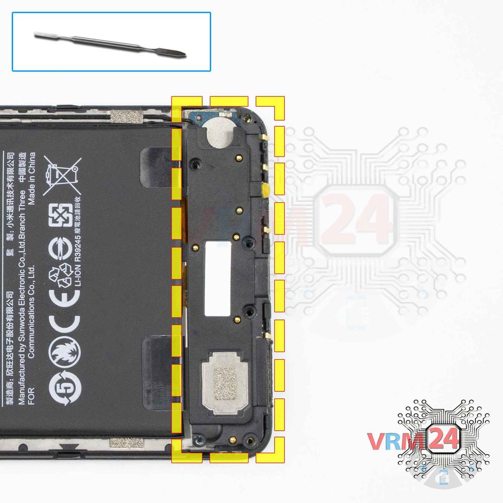
Remove the loudspeaker
Remove the loudspeaker assembly with antennas.
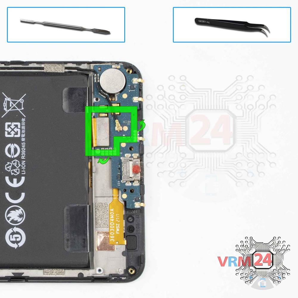
Step 11.
Disconnect the connectors
Disconnect the coaxial cable connector, cable to the mainboard, on the daughterboard.
⚠ Do not pull on the cable or pry it with a sharp tool, the connectors are pretty weak and break easily, or the cable falls out of the end (lug).
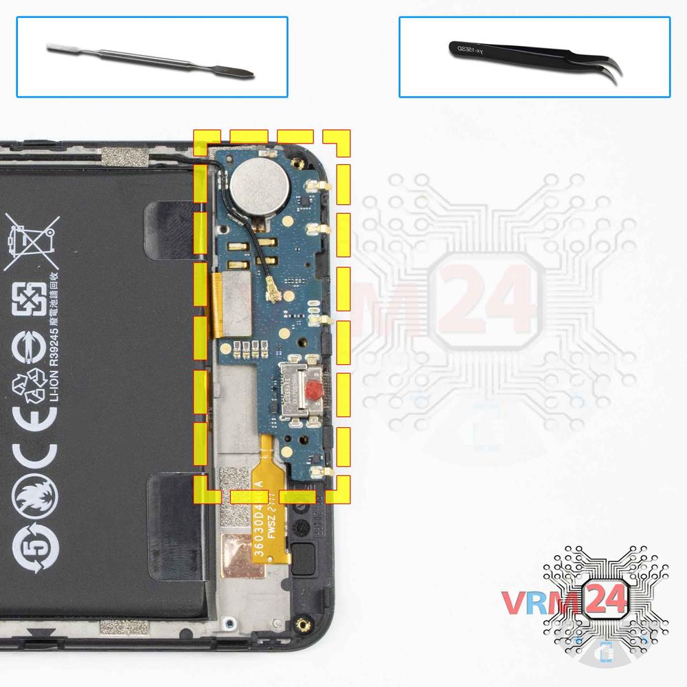
Step 12.
Remove the sub-board
Remove the sub-board. It is glued to the frame with metalized tape, so to facilitate the process, the board can be heated a bit.
ℹ️ The board contains a charging port (Micro USB), microphone, spring contacts for the speaker, and an antenna unit.
⚠ It is not necessary to insert the tool under the board when removing the sub-board. Internal components could be damaged.
Step 13.
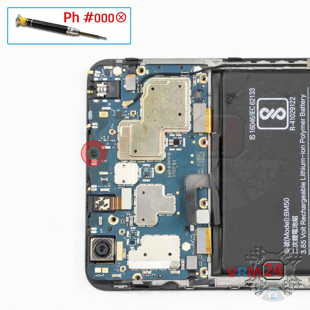
Unscrew one screw
Using a screwdriver (Phillips 1.5 mm PH000), unscrew one screw securing the motherboard.
Step 14.
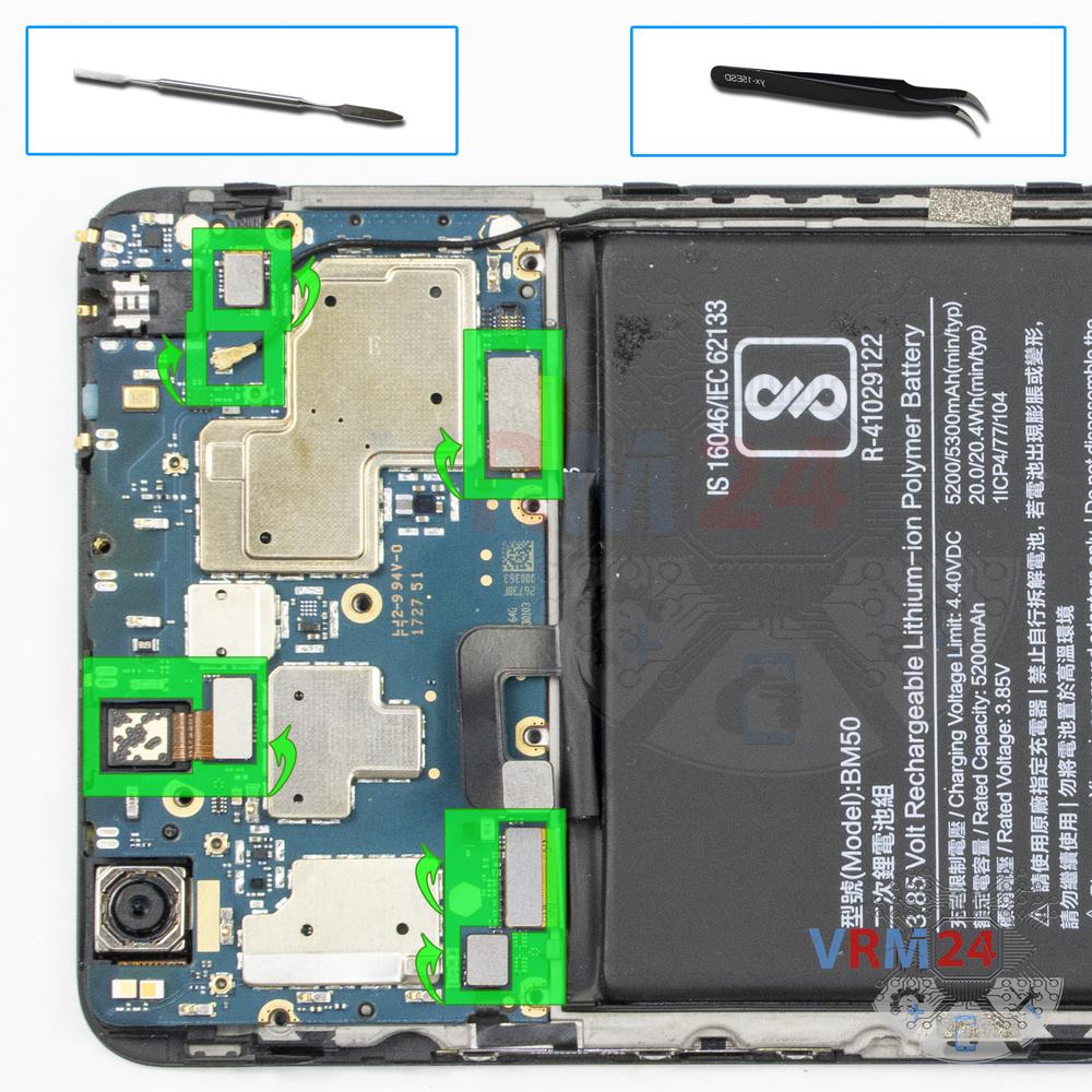
Disconnect the connectors
Pry up the connectors of power volume buttons cable, display cable, touchscreen cable, inter-board cable, and coaxial cable. Also, remove the front (selfie) camera.
⚠ Be careful when removing the cables from the connectors, the cables are pretty thin, and it is easy enough to break them or damage the contact tracks inside.
Step 15.
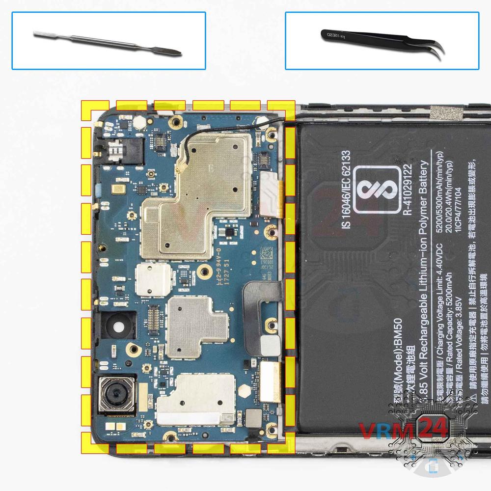
Remove the motherboard
Carefully remove the printed circuit board. There is no need to use a lever or try to reach the board by force. Make sure that nothing is getting in the way or holding the board.
⚠ Do not bend the circuit board when removing it or push tools under it. Unbeknownst to yourself, you can damage components or cables from the inside.
Step 16.
Remove the rear camera
Pry up the connector and remove the rear camera.

If you have a question, ask us, and we will try to answer in as much detail as possible. If this article was helpful for you, please rate it.

10979
Views
5
Likes
—
Share
0
Questions
Related Instructions
Related Reviews
Related Blog
Top instructions
Check our
Top Xiaomi instructions most liked by readers
New instructions
Check our
New Xiaomi brand instructions on vrm24.com