








Recommended tools
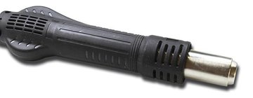
Heat gun
Screwdriver Phillips #000

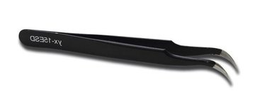
Tweezers
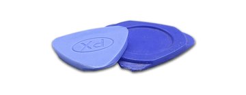
Non-metallic tool
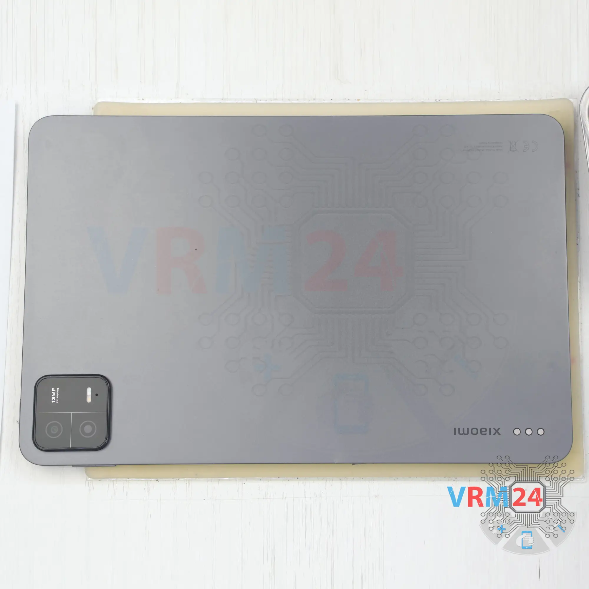
Disassembly/Repair of the mobile device Xiaomi Pad 6 (Xiaomi Pad 6 23043RP34G) with each step description and the required set of tools.
11107
Views
3
Likes
—
Share
3
Questions

Step 1.
Before disassembling!
⚠️ Before disassembling, do not forget to turn your phone off.
Step 2.
Open the display module
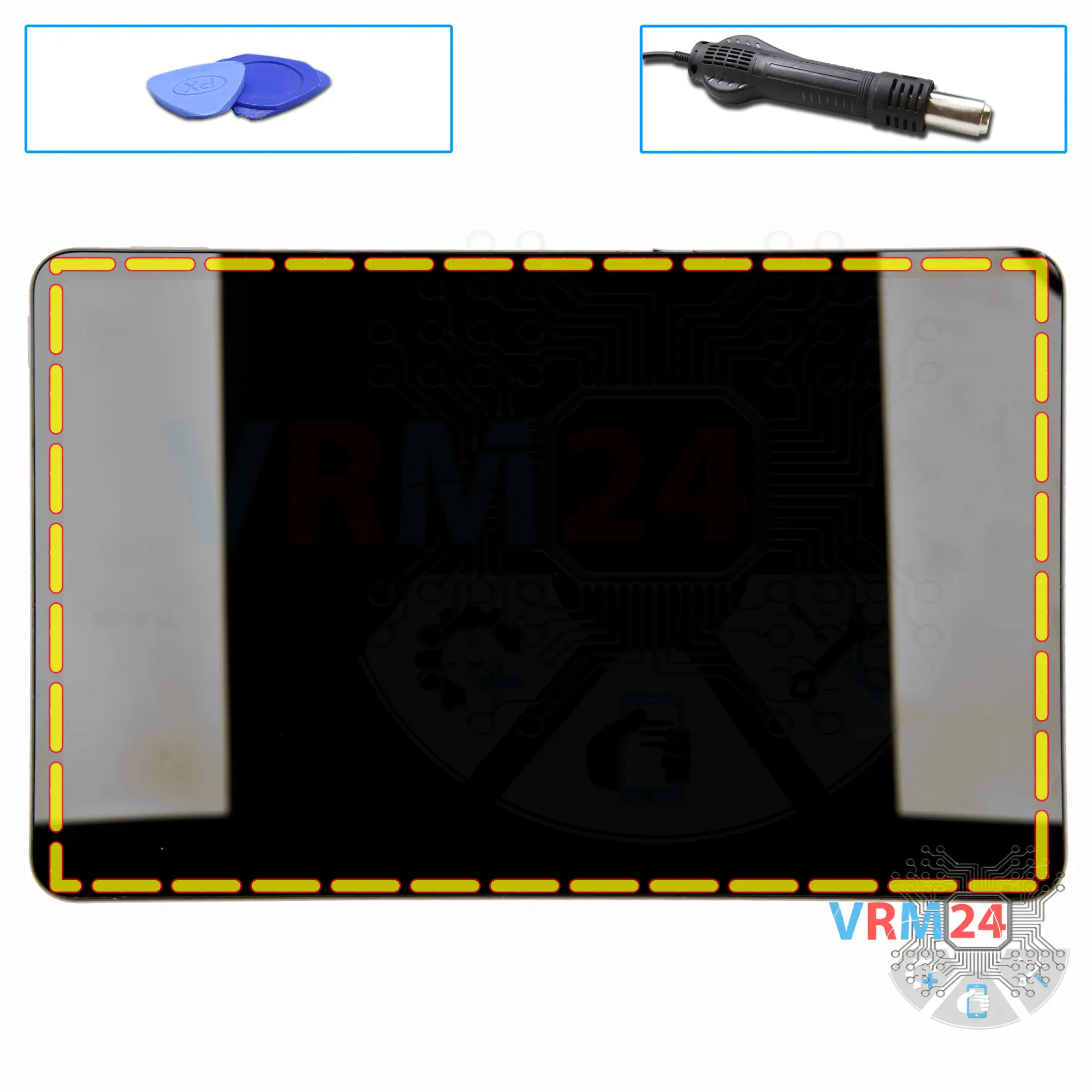
Since we don't have a card tray, we'll go straight to heating the surface of the display.
We heat to a temperature of about 75° C or 170° F. For this we use a heating mat.
We strongly do not recommend using a hair dryer for this disassembly, and in general we do not recommend disassembling this model by yourself and at home. Since the display is extremely thin, it is really difficult to disassemble. And it is also really hard to heat the display evenly, you need to have special equipment. We recommend to go to repair workshops to disassemble this model.
And after heating the display, we can proceed to its detachment.
To remove the display, we use a plastic film, it is a protective film from a new display or a film from the stationery store.
We insert it into the gap between the housing and the display and run it along the length detaching the display. We additionally use plastic tools to prevent the display from sticking back on.
Disassembly takes about 30 minutes, so we have to be careful and attentive at every step of disassembly. And the disassembly is quite complicated.
It is important to determine where the cables pass and be in this place especially careful not to damage the cables with tools and of course to open the display from the right side.
Step 3.
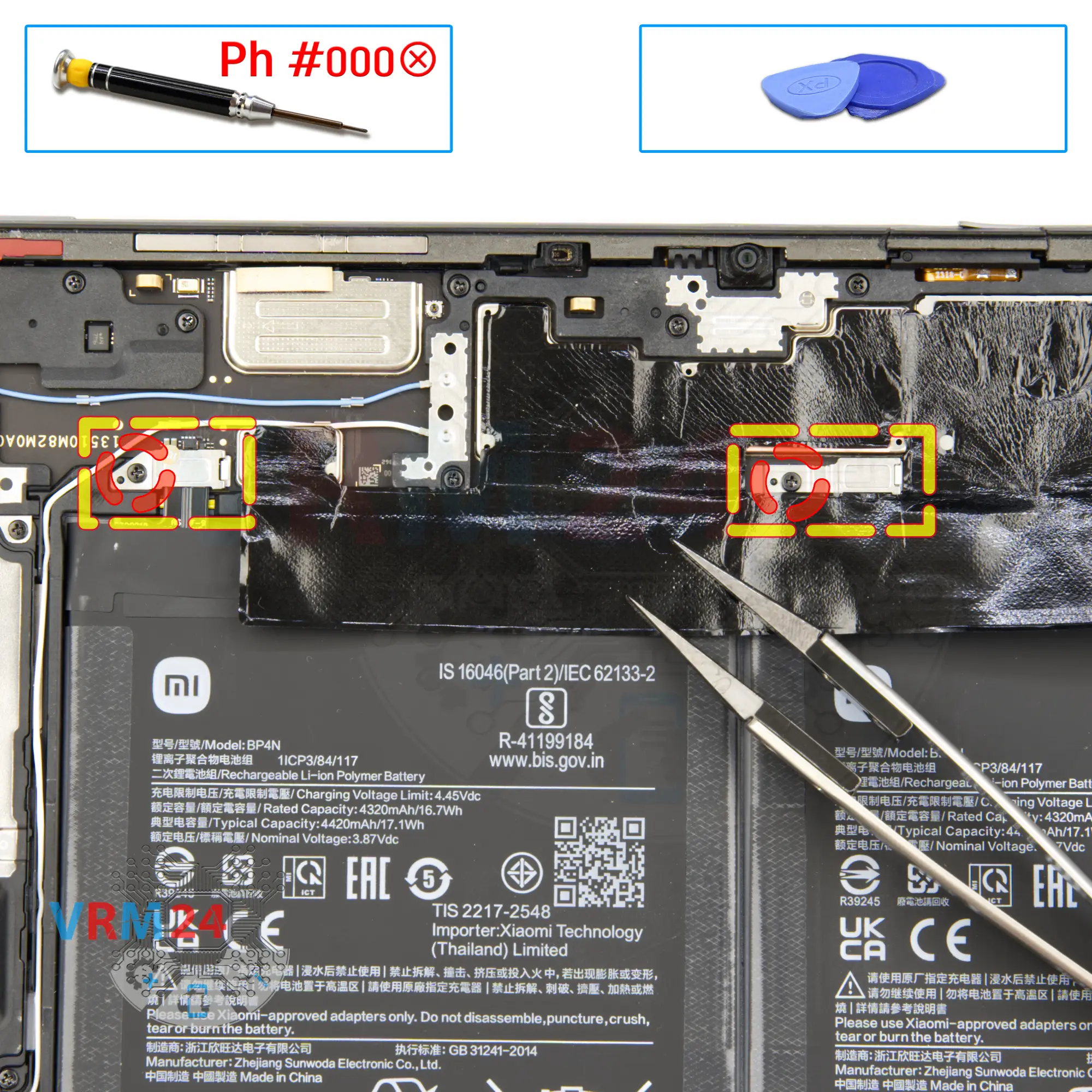
Unscrew the screws
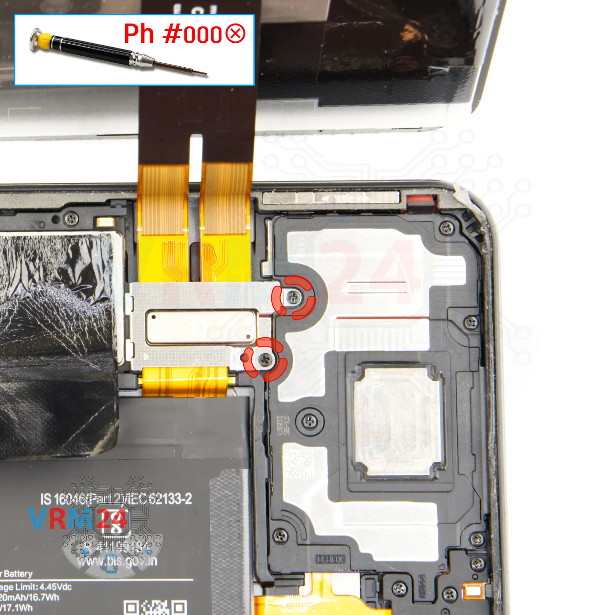
Unscrew the two screws that secure the display connectors. We use a 1.5mm Phillips screwdriver or #000.
Step 4.
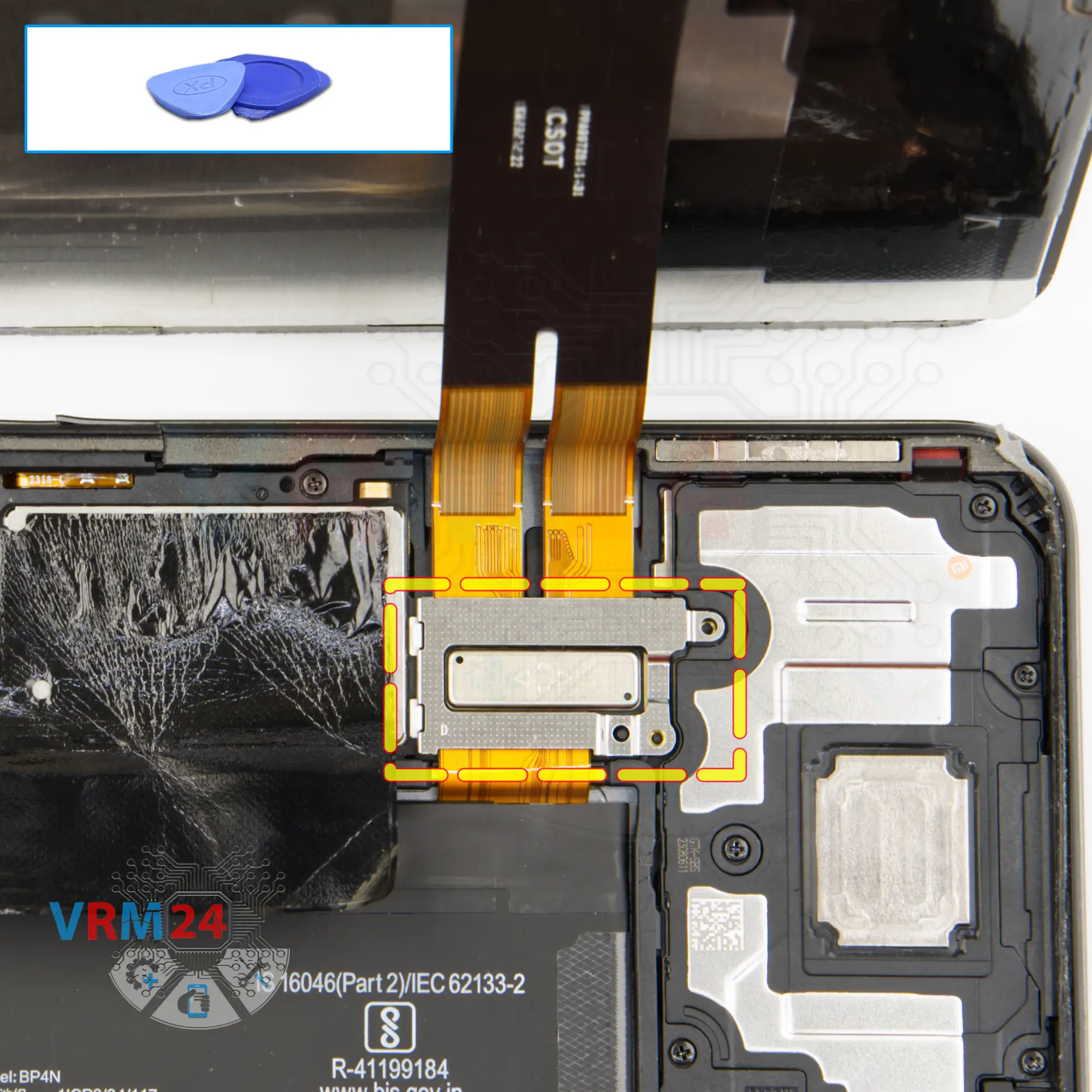
Remove the bracket
Carefully remove the bracket with a non-metal tool.
Step 5.
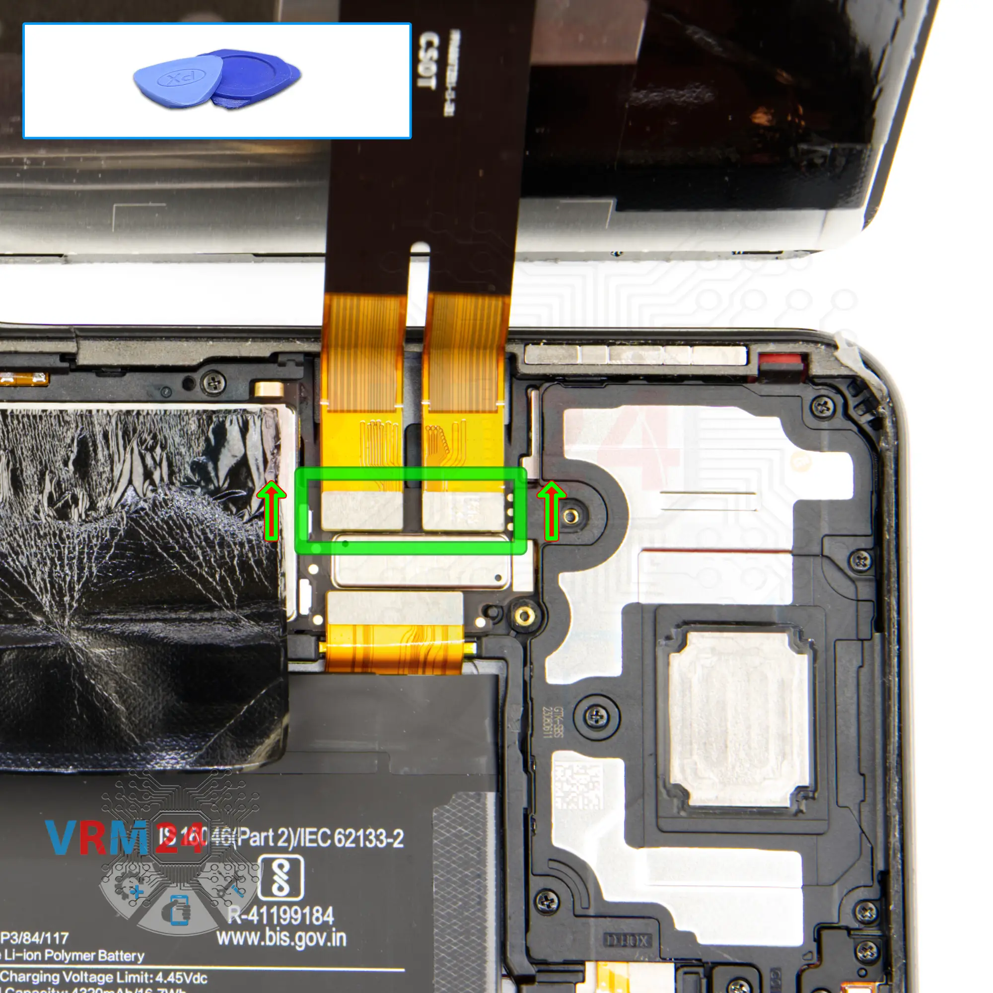
Disconnect the connectors
Disconnect the connectors, and we can carefully remove the display module.
Step 6.
Unscrew the screws
Using a screwdriver Phillips 1.5 mm (PH#000), unscrew the two screws and remove the brackets holding the connectors.
Step 7.
Disconnect the battery connector
Disconnect the battery connector as soon as you can. Use a non-metallic or plastic tool to avoid any damage.
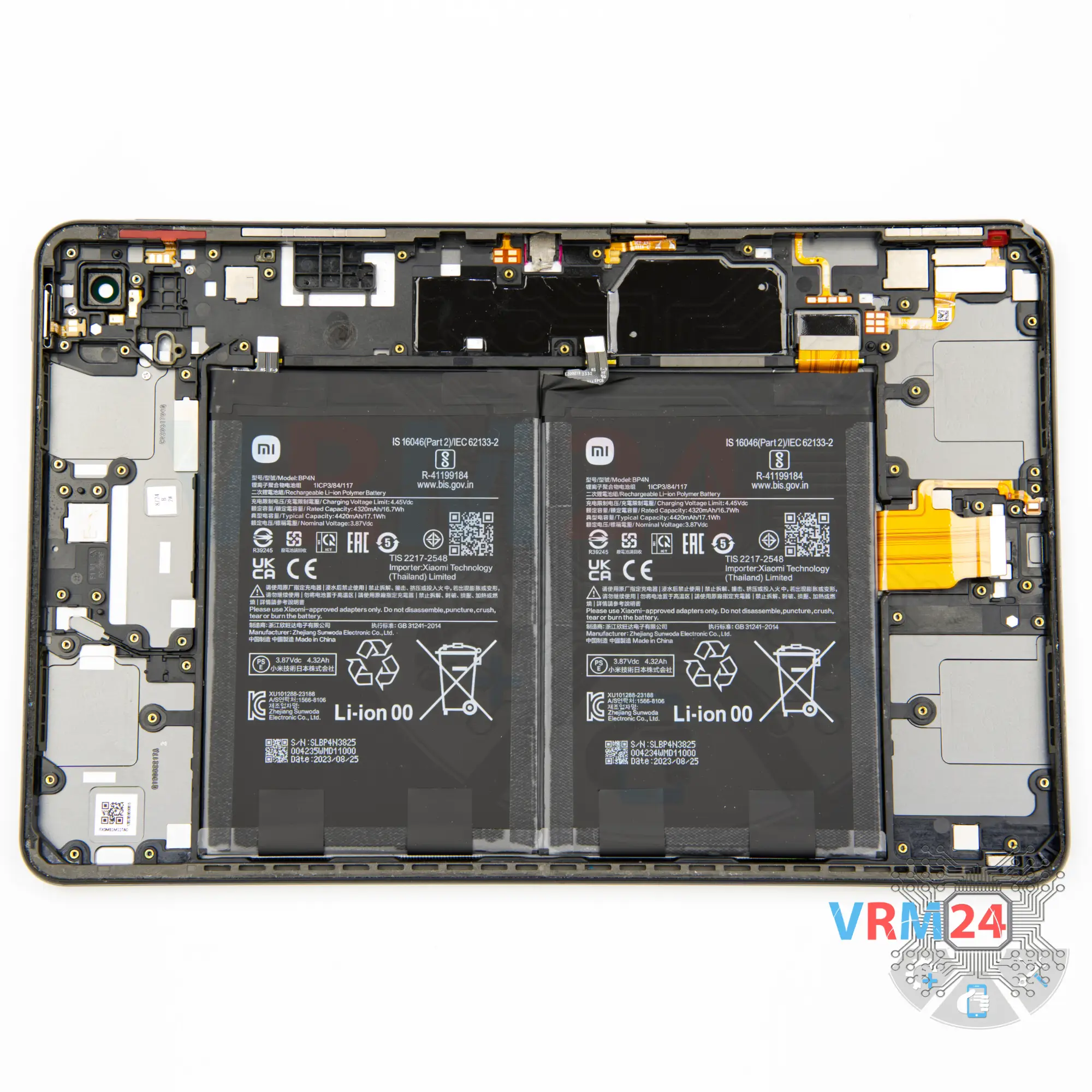
ℹ️ The Xiaomi Pad 6 model has two batteries BP4N with a capacity of 4320 mAh (also known as a rechargeable battery).
Step 8.
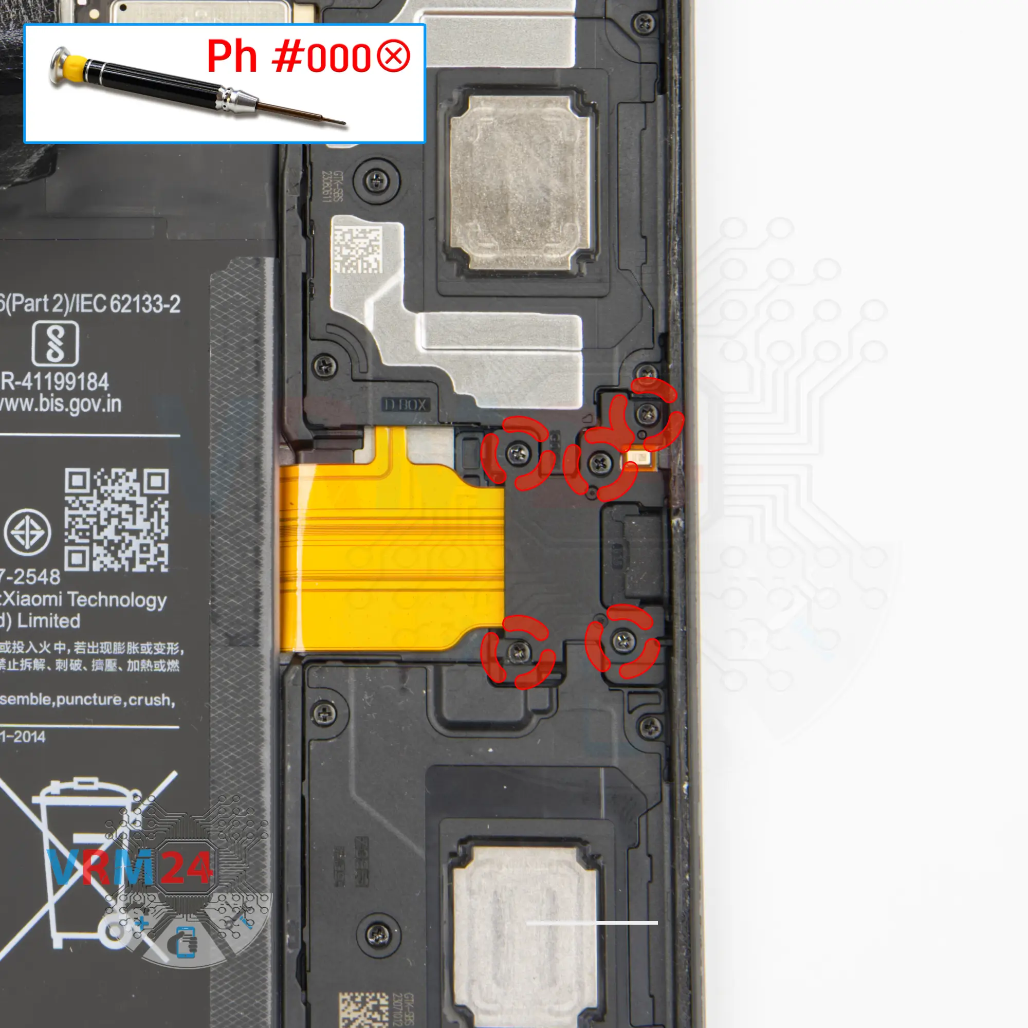
Unscrew the screws
Using a screwdriver Phillips 1.5 mm (PH#000), unscrew the five screws securing the charging port.
Step 9.
Open the cover
Carefully remove the cover hiding the small board with a charging port.
Step 10.
Unscrew the screws
Using a screwdriver Phillips 1.5 mm (PH#000), unscrew the five screws securing the loudspeaker.
Step 11.
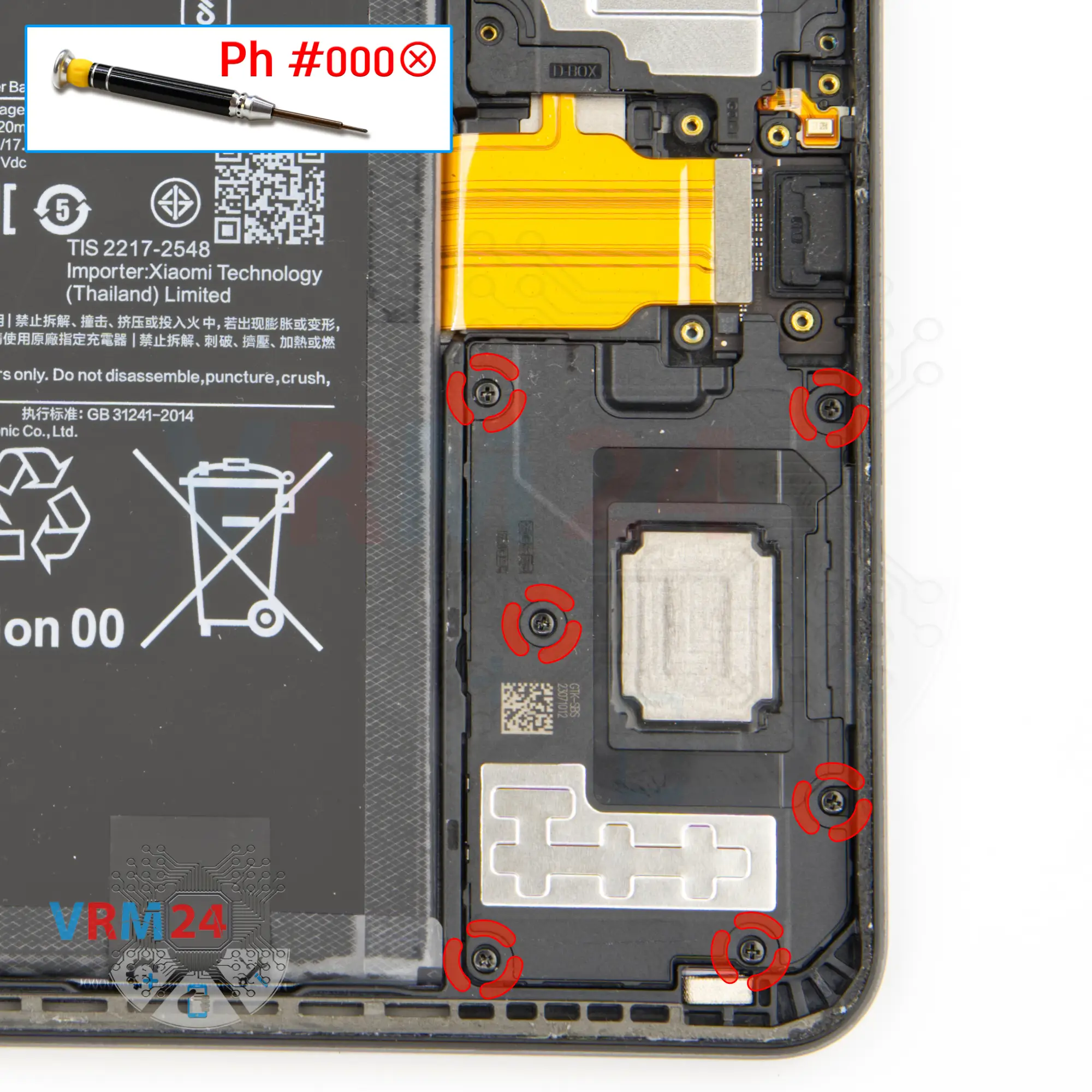
Unscrew the screws
Using a screwdriver Phillips 1.5 mm (PH#000), unscrew the six screws securing another loudspeaker.
Step 12.
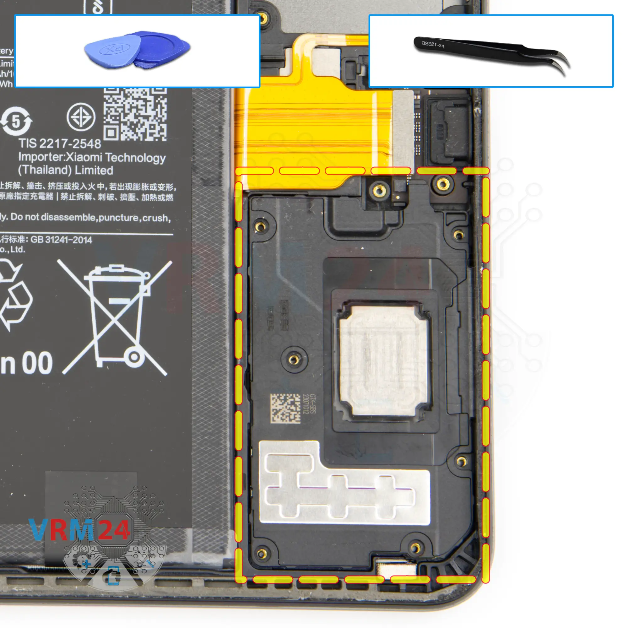
Remove the loudspeaker
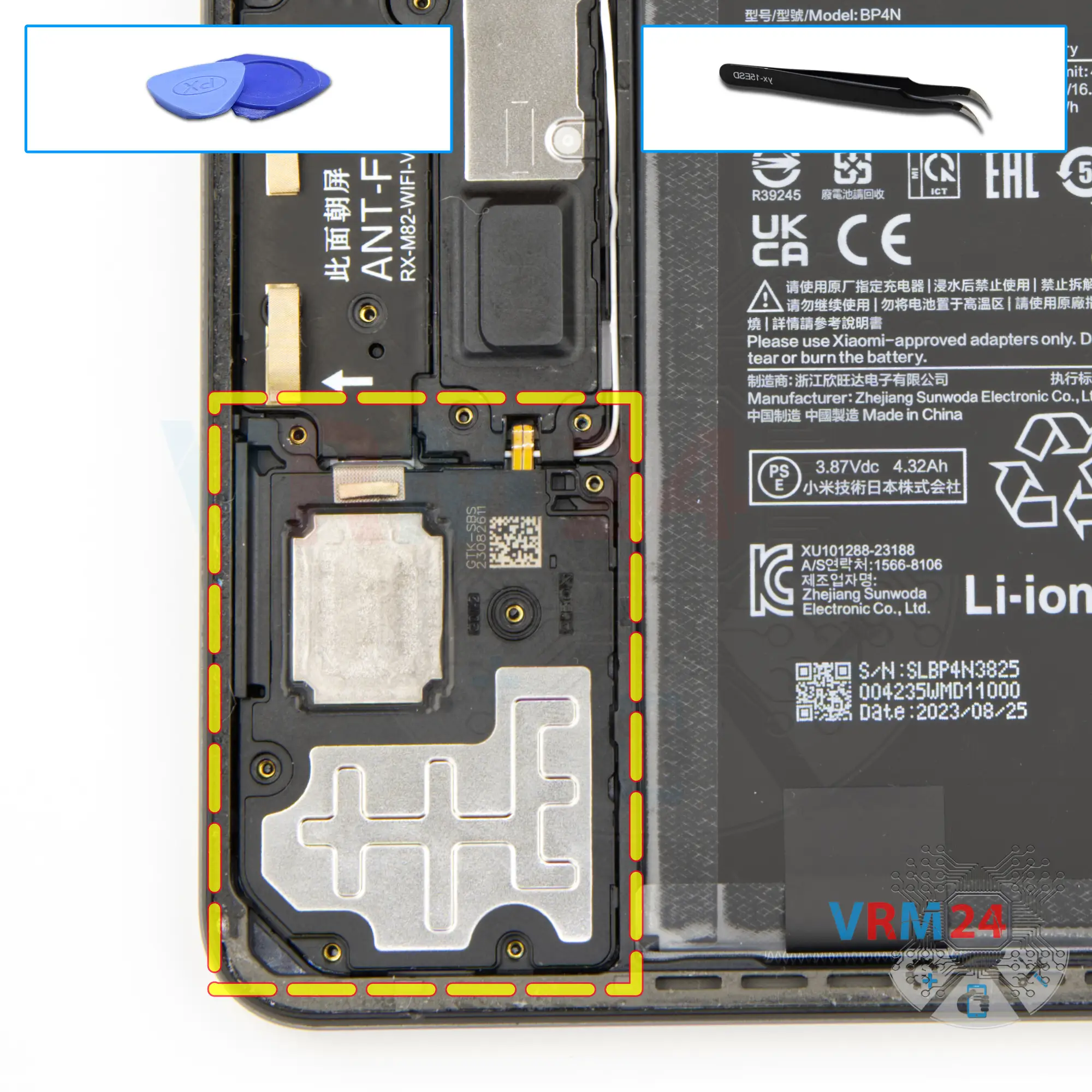
So, we can detach the first loudspeaker. Gently hook it at the edge and lift the speaker out.
Step 13.
Remove the loudspeaker
We remove the second speaker in the same way. Gently hook it at the edge and lift the speaker out.
Step 14.
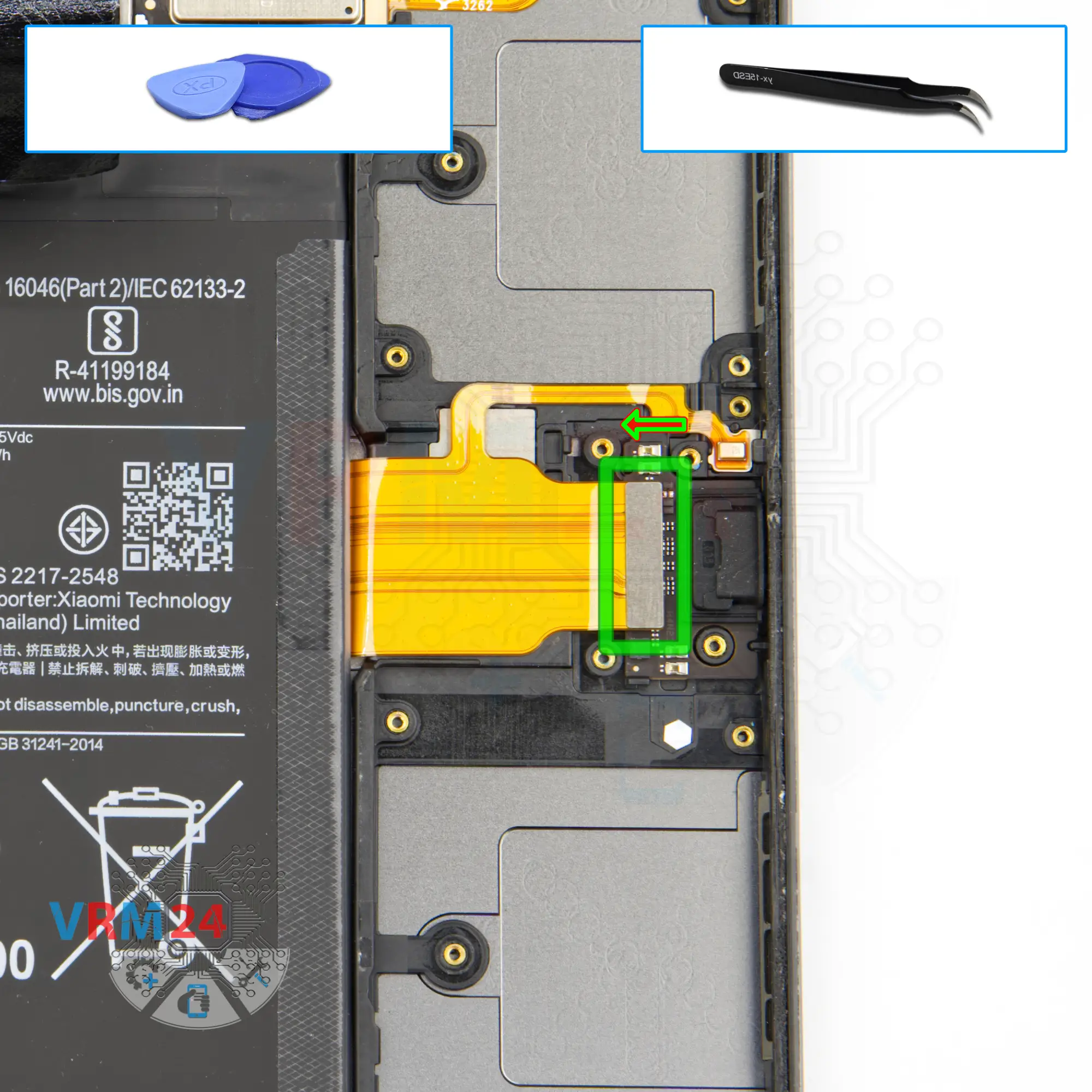
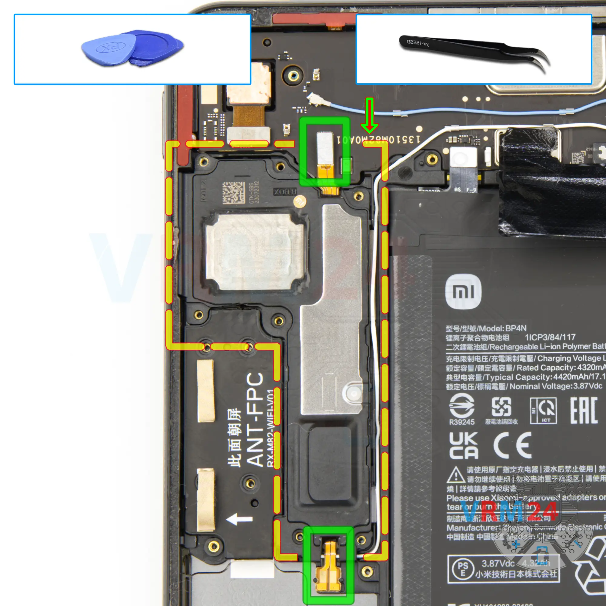
Disconnect the connector
Disconnect the inter-board cable connector.
Step 15.
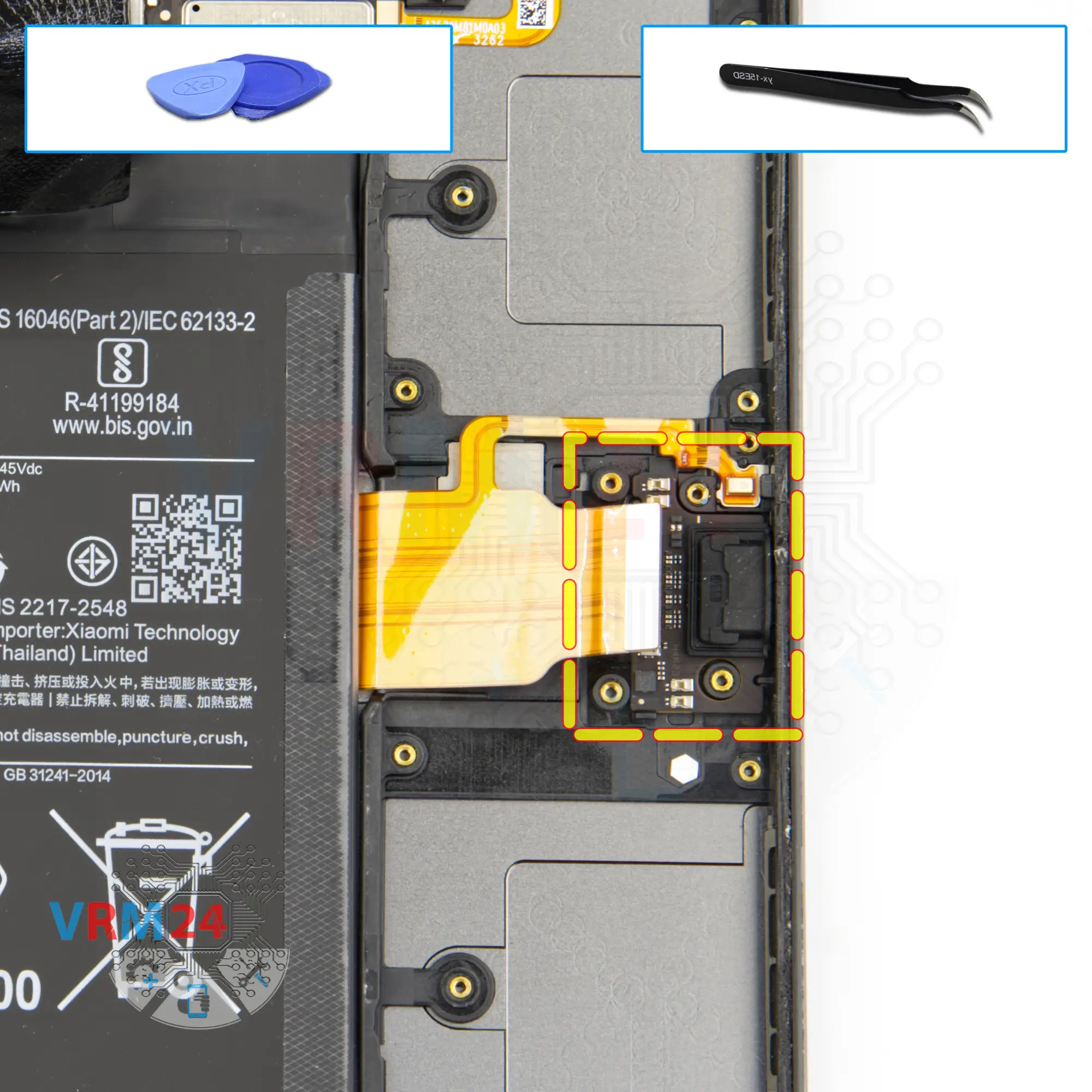
Remove the charging port
We move on to detach the small board with the charging port. Carefully lift it by the edge and try to pull out the board.
The board is slightly recessed and inserted into the screw bases.
Step 16.
Unscrew the screws
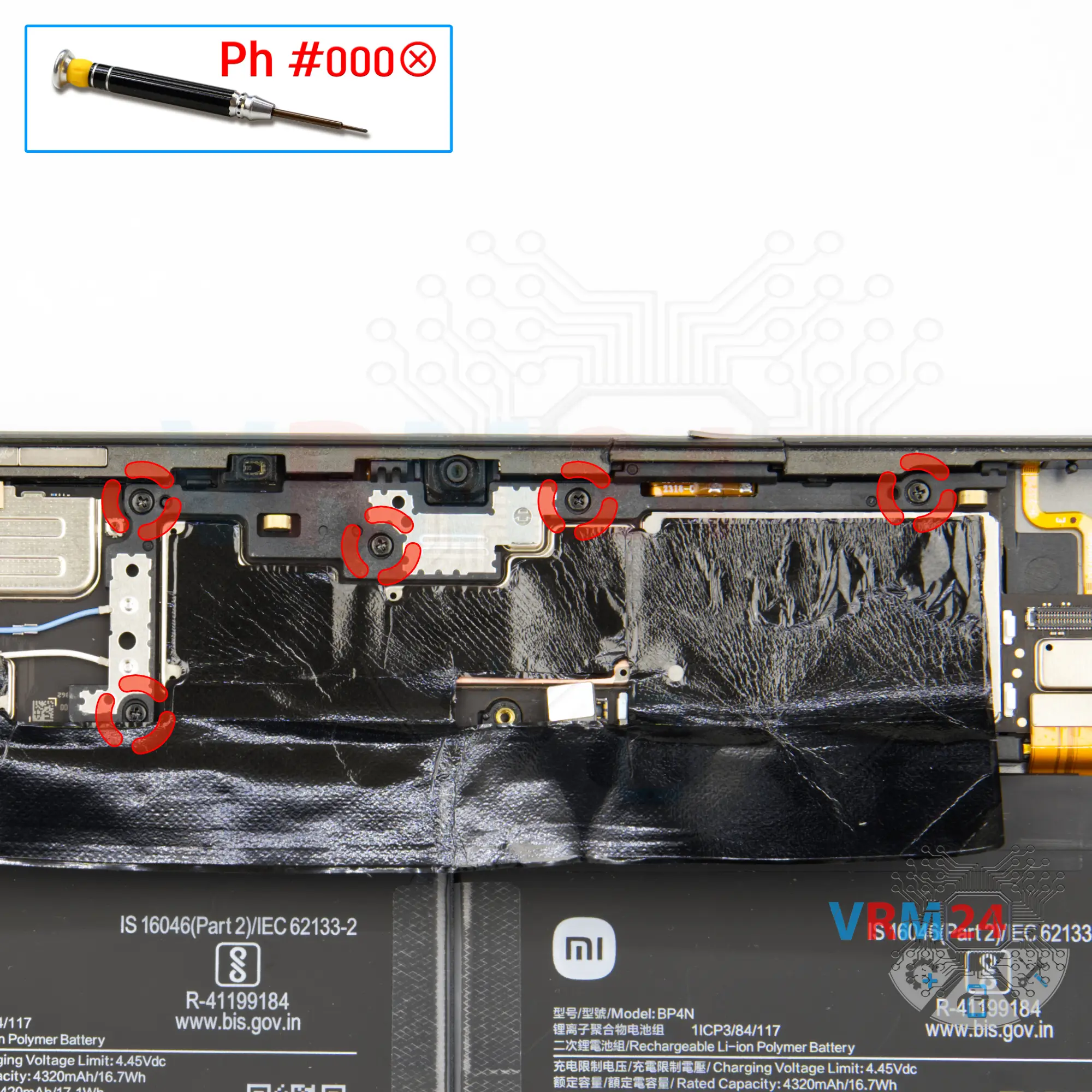
Using a screwdriver Phillips 1.5 mm (PH#000), unscrew the seven screws.
Step 17.
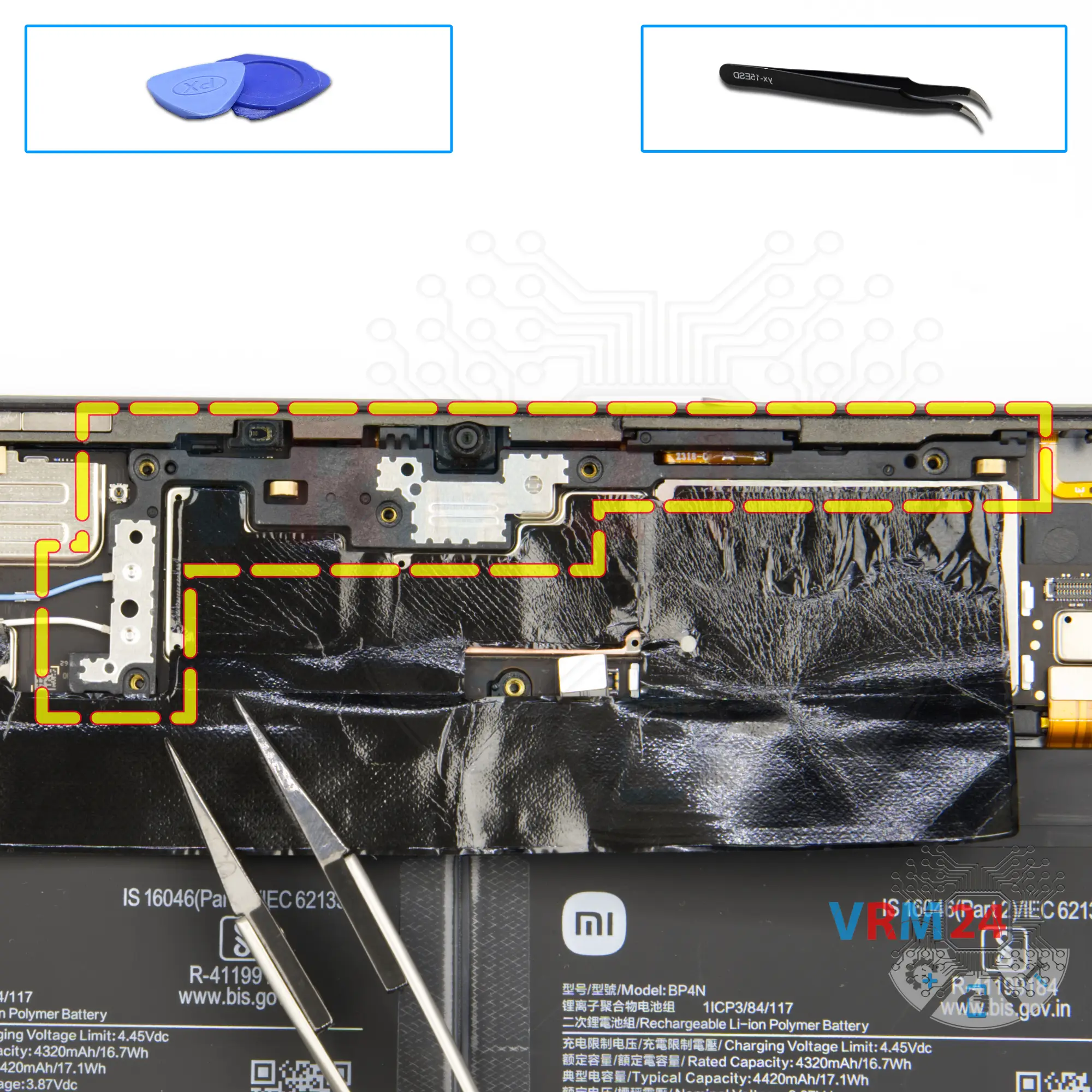
Open the cover
Let's move on to detaching the cover that hides the rear camera. The cover also secures the motherboard.
Step 18.
Unscrew the screws
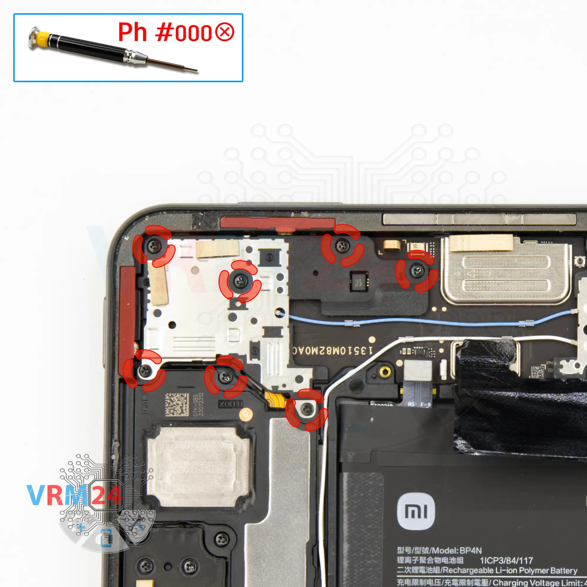
Using a screwdriver Phillips 1.5 mm (PH#000), unscrew the thirteen screws securing the speakers.
Step 19.
Remove the loudspeaker
And we can detach the next loudspeaker. Gently pry up the edge and remove the speaker.
Step 20.
Remove the loudspeaker
Then we need to unglue the connector pad, disconnect a connector on the other side and detach the last loudspeaker.
Step 21.
Unscrew the screws
Next, we have to unscrew the five screws on the motherboard that hold the motherboard and the small frame.
Step 22.
Open the cover
Remove the small frame that holds the connectors.
Step 23.
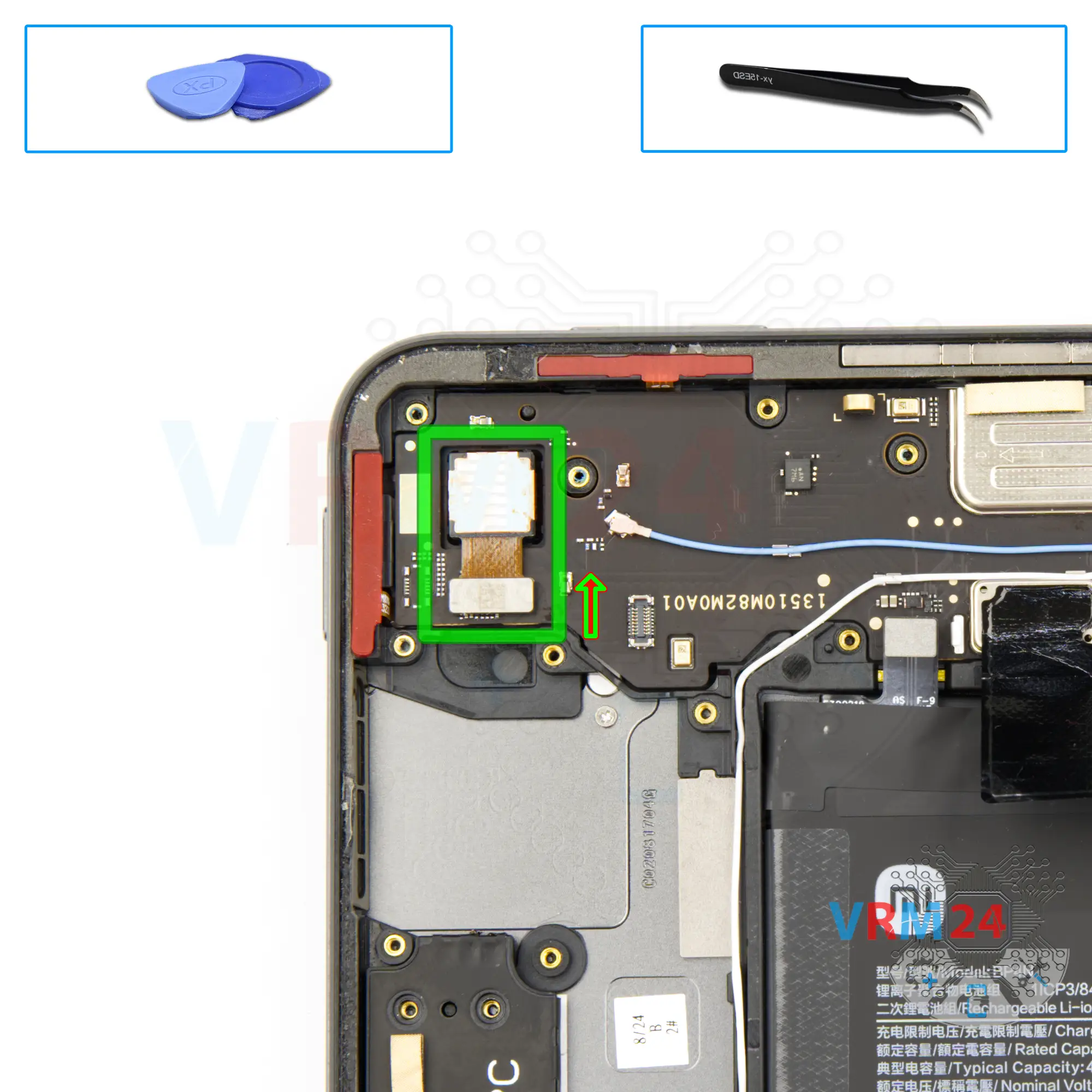
Remove the rear camera
And we can detach the rear camera.
Step 24.
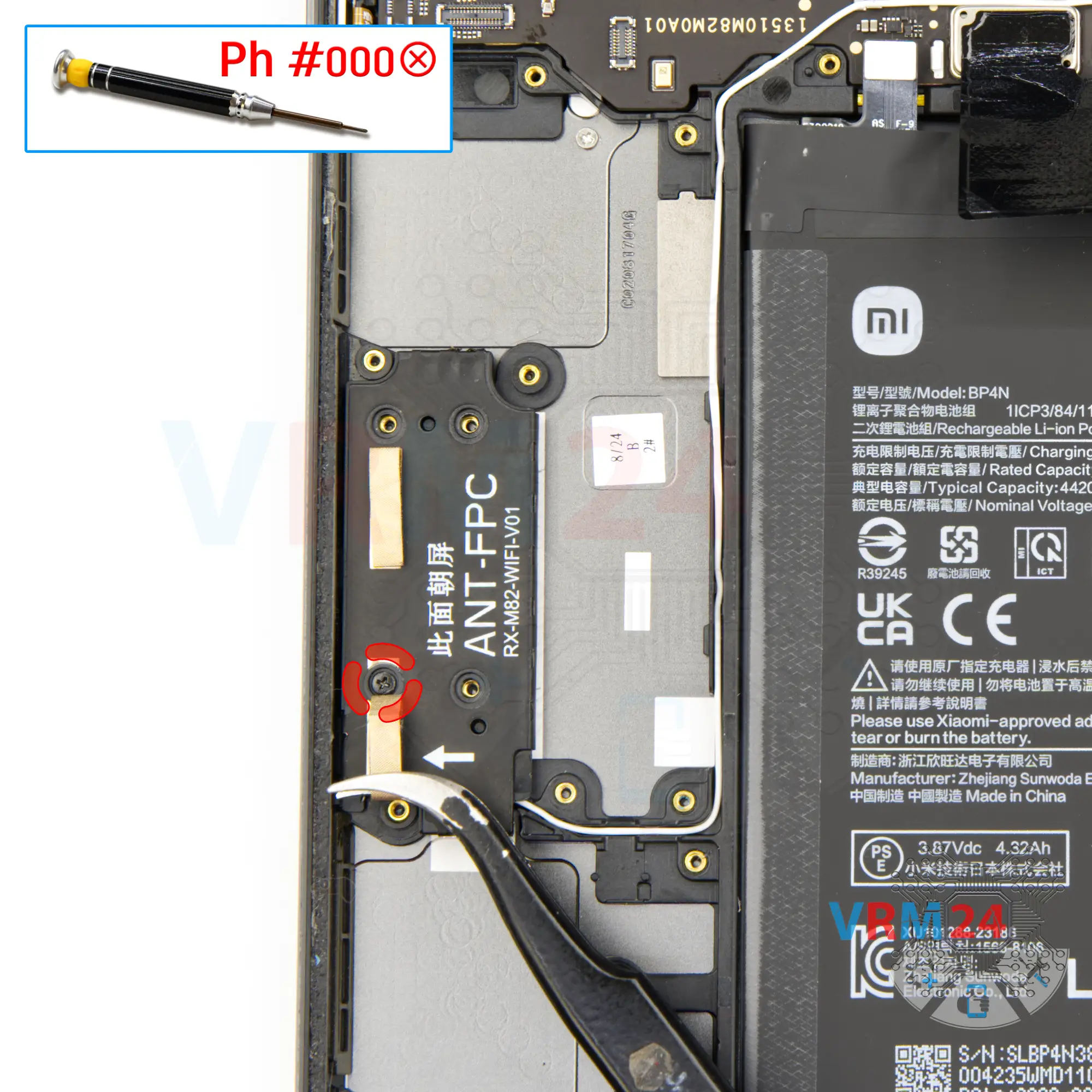
Unscrew one screw
So, we're going back to the cover.
We find a screw under the brown gasket and check that there are no more screws and unscrew this screw with a Phillips screwdriver.
Step 25.
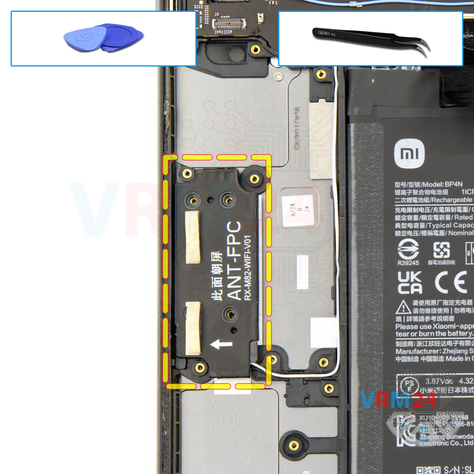
Open the cover
Now we can remove the cover easily.
Step 26.
Remove the small board
Under the cover we have a small antenna board with a coaxial cable.
We disconnect one connector on the motherboard and remove the small board and coaxial cable.
Step 27.
Disconnect the connectors
Disconnect the connectors of the front camera and inter-board cable on the motherboard.
Step 28.
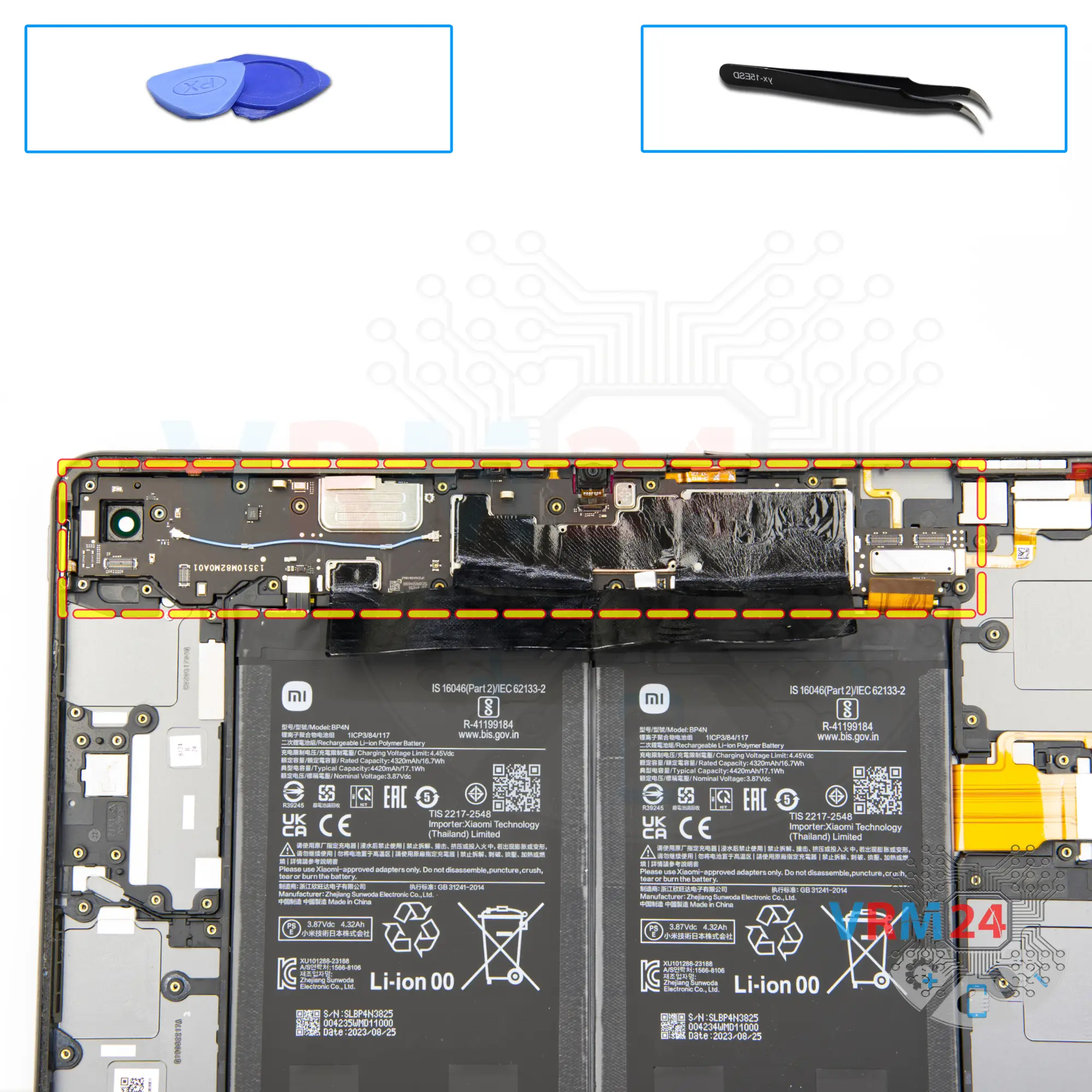
Remove the motherboard
We can try to remove the motherboard. We make sure that nothing is in our way and we remove the motherboard.
⚠️ Do not bend the circuit board when removing it or push tools under it. Unbeknownst to yourself, you can damage components or cables from the inside.
Step 29.
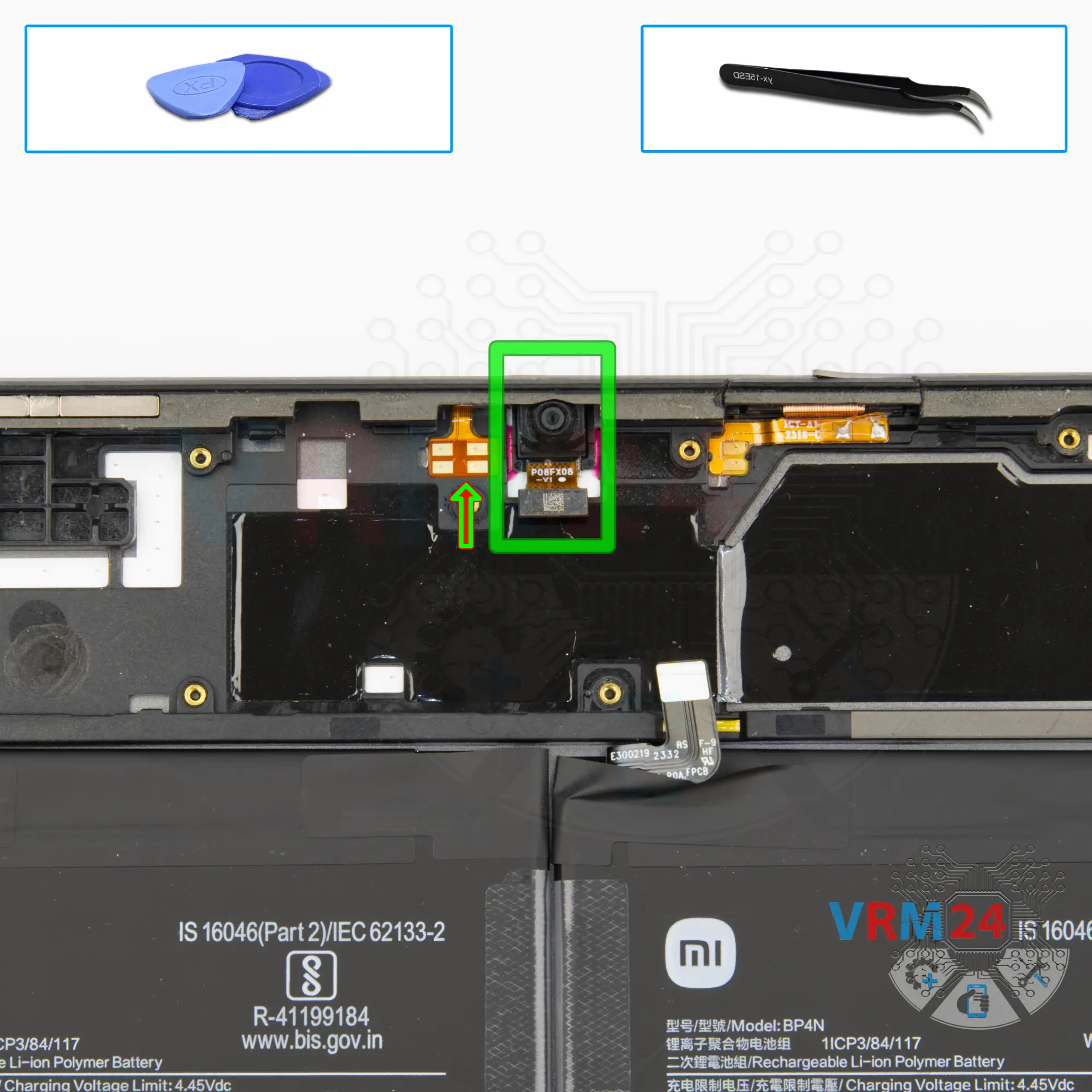
Remove the front camera
Now we need to detach the front camera. We need to carefully hook the bottom of the camera and lift it off.
The camera is taped, so we need to do everything carefully and not to damage the camera cable.
Step 30.
In the housing remained
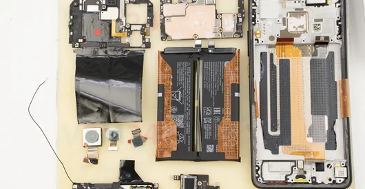
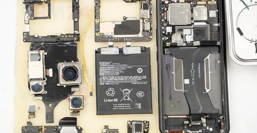
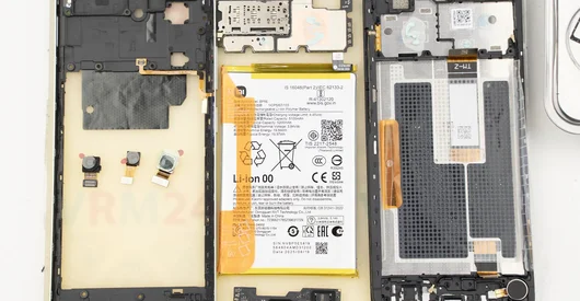
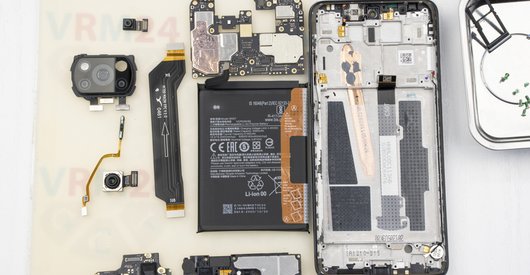
ℹ️ In the housing remained: the battery, buttons and microphones.

If you have a question, ask us, and we will try to answer in as much detail as possible. If this article was helpful for you, please rate it.

11107
Views
3
Likes
—
Share
3
Questions
Related Instructions
Related Reviews
Related Blog

Popular Questions

Xiaomi Pad 6
what are the heating surfaces brand and model you are using or can recommend
alexander7
Xiaomi Pad 6
is there a insulation layer between the back case and the cpu?
alexander7
J
Xiaomi Mi 5
Hello i need to replace home button how to do after ? Thanks
Julien Claudio2
Xiaomi Redmi Note 9 Pro
I need a Main boards Xiaomi Redmi Note 9 Pro can you help me please
kp_praveen
M
Xiaomi Mi 5S Plus
Where can I find the "Termistor"?
Macarena Gonzalez15Top instructions
Check our
Top Xiaomi instructions most liked by readers
New instructions
Check our
New Xiaomi brand instructions on vrm24.com