⚠️️ Before disassembling, do not forget to turn your phone off.
Moderate
Recommended tools


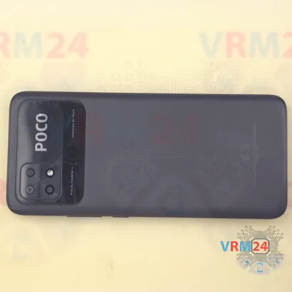
Disassembly/Repair of the mobile device Xiaomi POCO C40 (Xiaomi POCO C40 220333OPG) with each step description and the required set of tools.

Maxim Sivolap
Tech specialist, author
A longtime technician, the author.
Step 2. Remove the tray
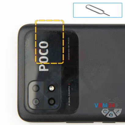
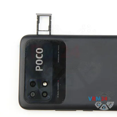
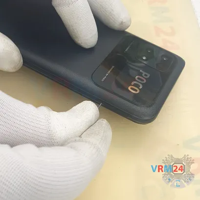
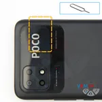
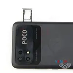
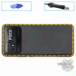
At the very beginning we need to remove the card tray for this we take a special tool, insert it into the hole and push out the combined tray for sim cards and memory cards.
Step 3. Open the back cover
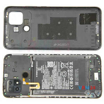
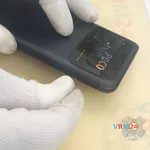
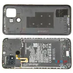
Then we move on to removing the back cover.
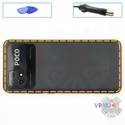
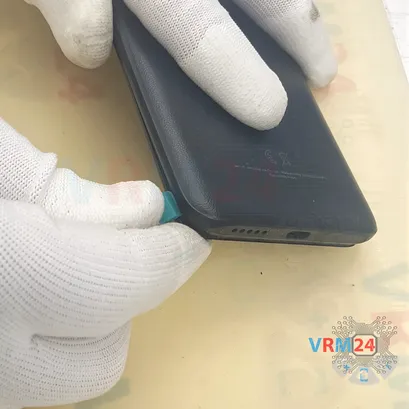
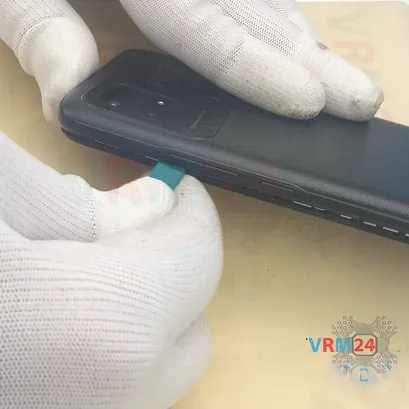
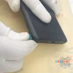
First we use a thin plastic film, insert it into the gap between the back cover and the display frame and carefully detach a few clips.
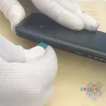
After that we can use a thicker tool. We run the tool along the edge to detach the back cover.
We always have to be careful on the corners, because there the cover is held especially tight.
And we also need to be careful around the side buttons, because they are physically located there.
⚠️️ This cover may be taped on the side, sometimes it is nesessary to heat sides a little with heat gun.
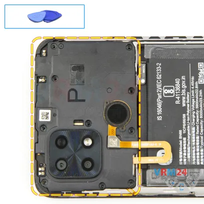
Step 4. Unscrew the screws
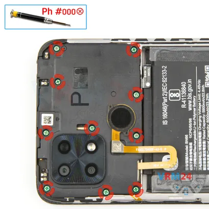
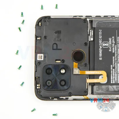
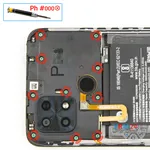
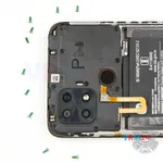
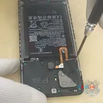
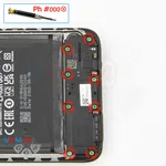
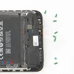
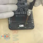
After that we need to unscrew the ten screws at the top, we use a 1.5mm Phillips screwdriver or #000.
If the screws do not come out well we can additionally use a magnetizer.
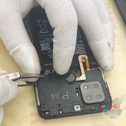
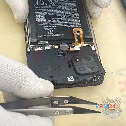
If the screws get stuck we can use tweezers to carefully remove the screws.
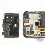
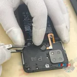
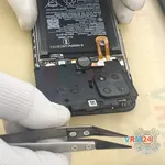
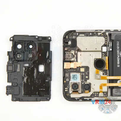
Step 5. Open the cover
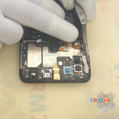
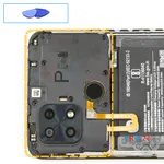
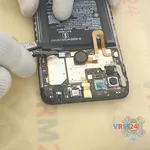
And we move on to detaching the cover. We have to be careful not to damage the fingerprint sensor cable.
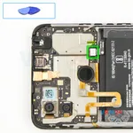
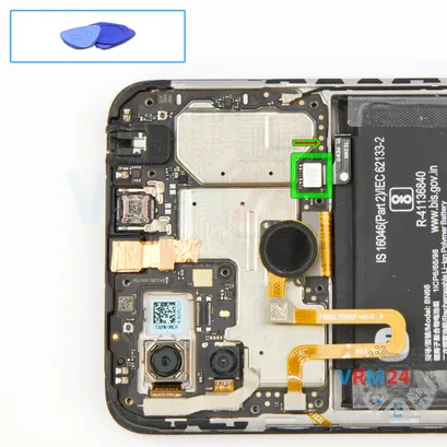
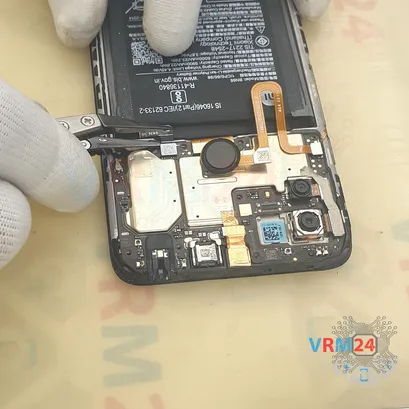
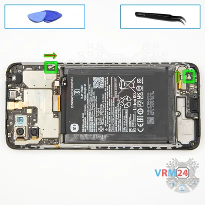
Step 6. Disconnect the battery connector
Disconnect the battery connector as soon as you can. Use a non-metallic or plastic tool to avoid any damage.
ℹ️️ The Xiaomi POCO C40 220333OPG model has a battery BN66 with a capacity of 6000 mAh (also known as a rechargeable battery).
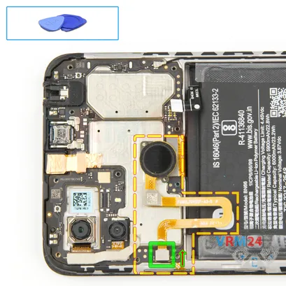
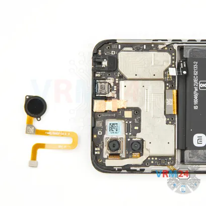
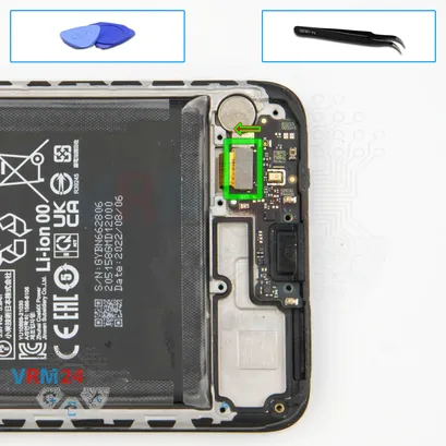
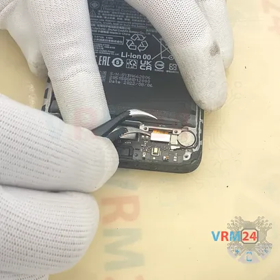
Step 7. Remove the fingerprint sensor
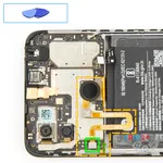
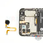
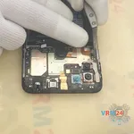
We disconnect the connector and remove the fingerprint sensor cable.
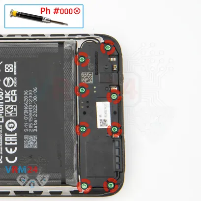
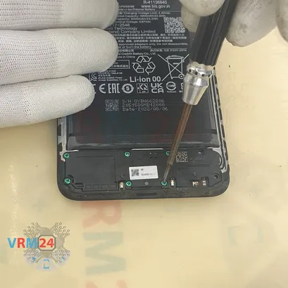
Step 8. Unscrew the screws
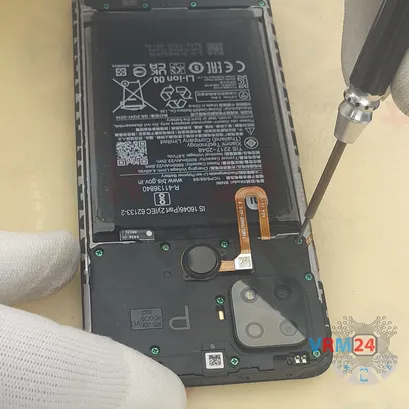
Then we move on to unscrewing the eight screws at the bottom for this we use the same Phillips screwdriver.
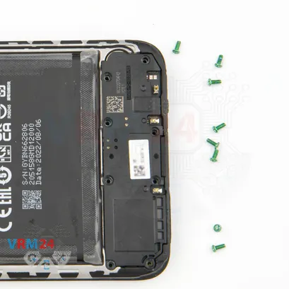
It looks like all the screws are the same, but we still recommend placing them in a certain order just in case.
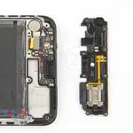
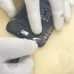
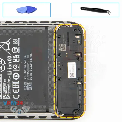
Step 9. Remove the loudspeaker
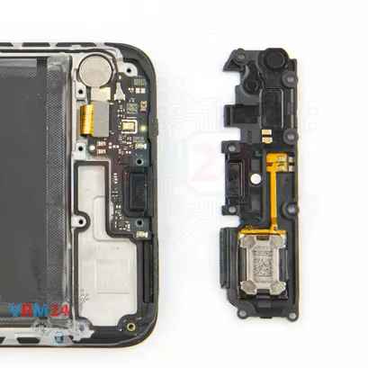
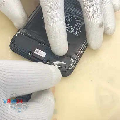
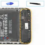
And we can detach the cover with the loudspeaker.
Find the right and convenient place to pry the cover off. Gently hook the cover, lift and remove it.
The loudspeaker is located on the inside of the cover.
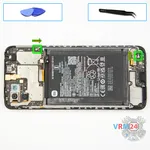
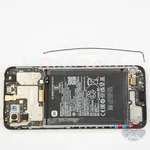
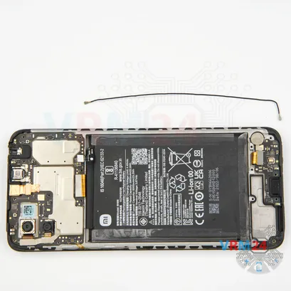
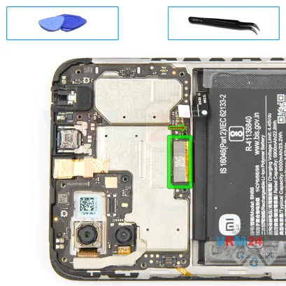
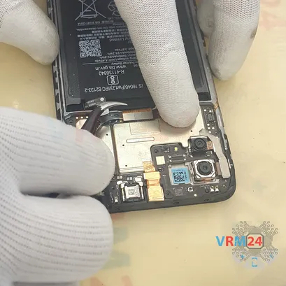
Step 10. Remove the coaxial cable
We disconnect the connectors on the both boards and remove the coaxial cable.
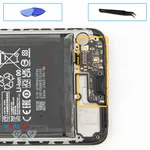
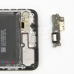
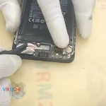
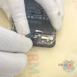
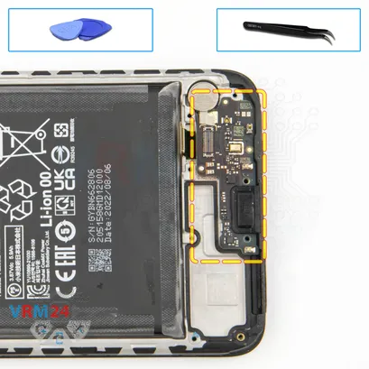
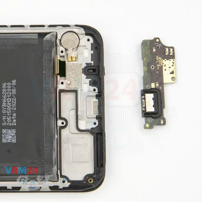
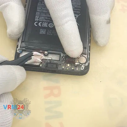
Step 12. Remove the sub-board
And we moving on to removing the sub-board.
First we need to peel off the heat dissipating foil that is taped on the sub-board and vibration motor.
On the sub-board are located charging port, microphone and other elements on the back side.
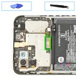
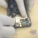
Step 13. Disconnect the connector
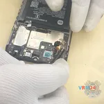
We disconnect the inter-board cable connector to the display on the motherboard.
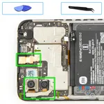
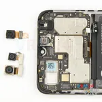
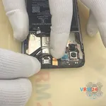
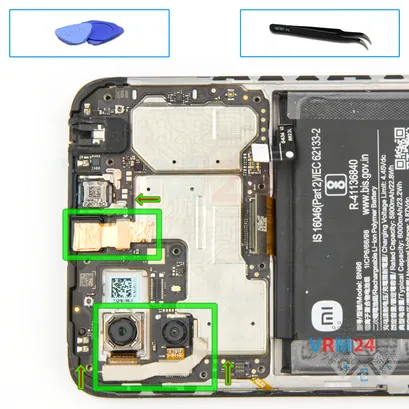
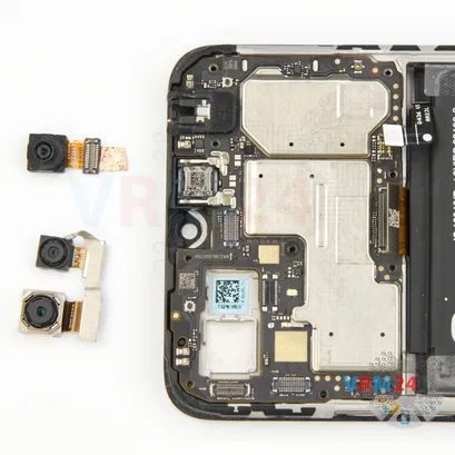
Step 14. Remove the cameras
And we move on to remove the cameras.
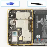
First, we have to peel back the heat dissipating foil and detach the front camera.
Then we detach the two rear cameras. It's better to hold the cameras so that they don't fall out and damage the lenses.
Step 15. Remove the motherboard
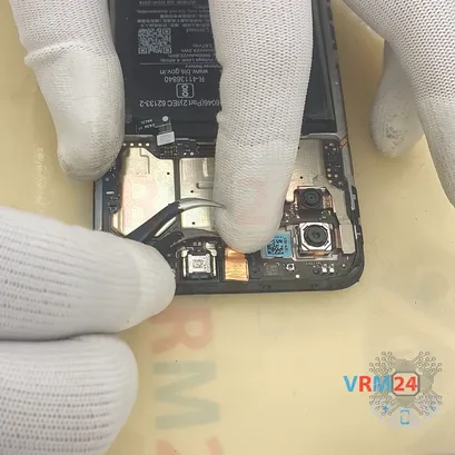
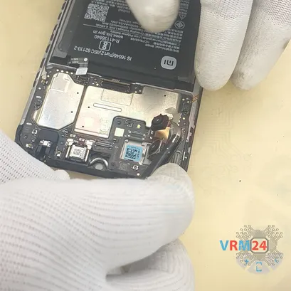
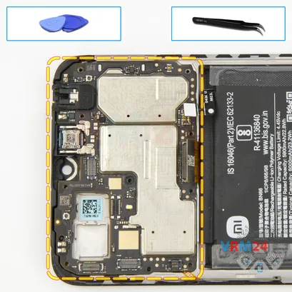
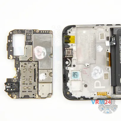
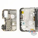
Now, we can detach the motherboard. Find the right place to hook, lift and remove the motherboard.
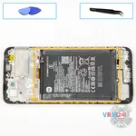
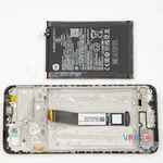
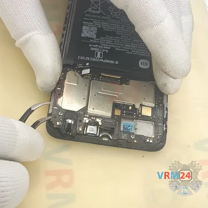
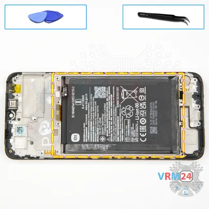
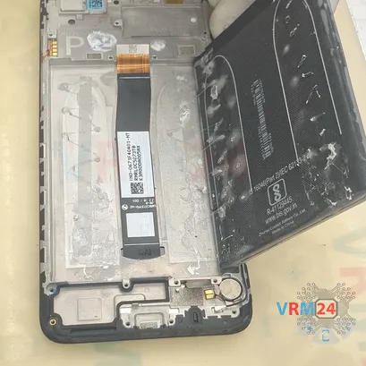
Step 16. Remove the battery
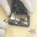
Finally, we move on to detaching the battery.
The battery in our case is glued on sealant, instead of the original adhesive. The battery has been previously separated or changed.
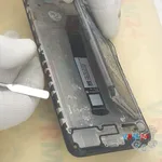
We start by using thin plastic film, carefully going over the edge cutting off the adhesive.
Then we can try to pry up the battery and see how firmly it holds.
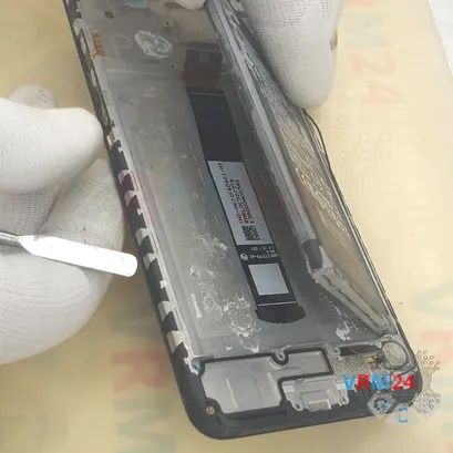
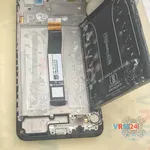
It is really important not to force it, otherwise we can damage the battery shell or the cable under the battery in the middle. Carefully lift the battery and use the plastic film to cut off the adhesive layer.
Then hold the battery and slip the tool behind the display cable and cut off the adhesive on the far side. The sealant is applied unevenly in small drops, so it is not difficult to cut it off. Anyway, we need to be extremely careful not to damage the cable.
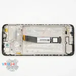
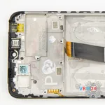
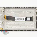
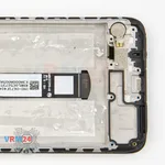
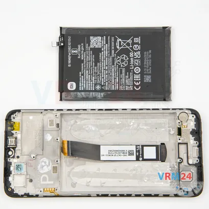
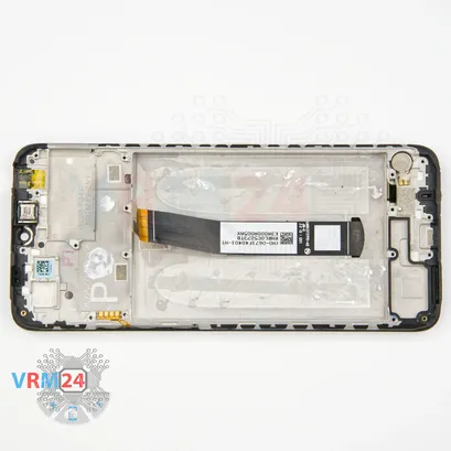
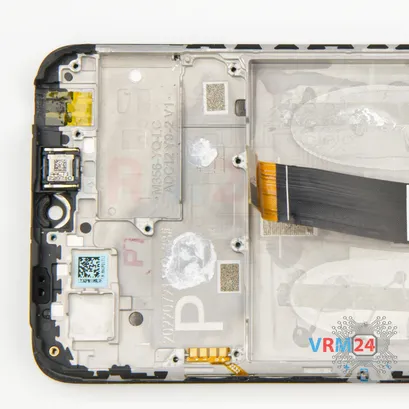
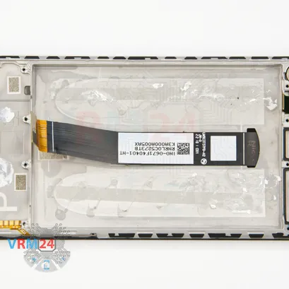
Step 17. In the display frame remained
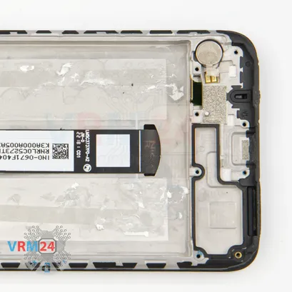
ℹ️️ In the display frame remained: the earpiece speaker, vibration motor.
Detailed disassembly instructions of Xiaomi POCO C40 in the video, made by our mobile repair & service center:
If you have a question, ask us, and we will try to answer in as much detail as possible. If this article was helpful for you, please rate it.

Evgenii Kuzmin
Senior maintenance service and repair engineer
Back to the list

