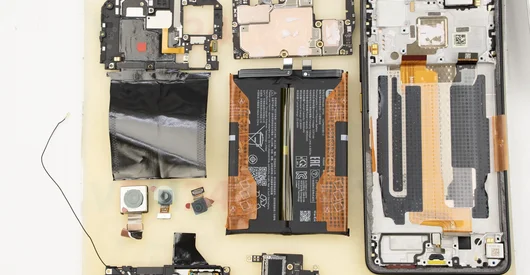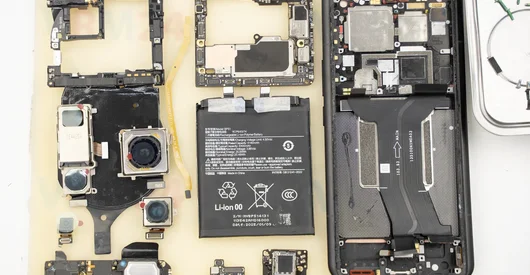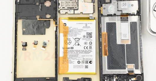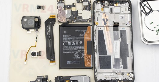
Recommended tools
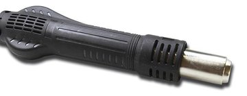
Heat gun
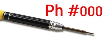
Screwdriver Phillips #000
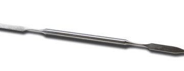
Opening tool / Spudger
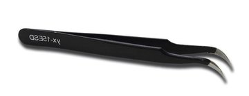
Tweezers
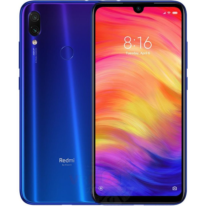
Disassembly/Repair of the mobile device Xiaomi Redmi Note 7 (Xiaomi Redmi Note 7 M1901f7G) with each step description and the required set of tools.
81112
Views
37
Likes
—
Share
5
Questions

Step 1.
Open the back cover
We recommend using a special heating device such as a separator machine, heat gun, or heating mat. It will simplify the process. You can use a home hairdryer, but you will have to make a nozzle by hand or have a suitable one in the kit to gently heat and concentrate the heat flow in the right place.
ℹ️ The surface of the back cover must be heated to soften the adhesive underneath. The approximate heating temperature is 50° C / 125° F.
Use a thin plastic film or pick for separation. To facilitate the process, you can use isopropyl alcohol. It is often most difficult to pass the tool between the parts to be divided. Choose the far edge from the FFC cables or buttons.
Do not use a lever or any force for separation that could damage the elements inside.
⚠️ Pay attention to the fingerprint sensor cable connected to the back cover from the inside.
After, we opened the back cover. Gently flip the cover over to disconnect connector fingerprint sensor.
Step 2.
Disconnect the connector
Carefully peel off the protective film. Disconnect the fingerprint sensor connector and remove the back cover.
⚠️Try to use non-metal or plastic tools to avoid short-circuits because the smartphone is still battery-powered.
Step 3.
Disconnect the connectors
Using a screwdriver (Phillips 1.5 mm PH000), unscrew 3 screws and remove the bracket holding the connectors.
Step 4.
Disconnect the battery connector
Disconnect the battery connector as soon as possible.
ℹ️ The Xiaomi Redmi Note 7 M1901F7G model has a battery BN4A with 4000 mAh capacity (aka rechargeable battery).
⚠️ It is highly recommended to disconnect the connector to avoid possible short circuits during disassembly.
Also, try not to use a metal tool to disconnect the rechargeable battery connector or do it carefully.
Step 5.
Unscrew the screws
Using a screwdriver (Phillips 1.5 mm PH000), unscrew 8 screws.
Step 6.
Remove the loudspeaker
Remove the loudspeaker assembly with antennas.
Step 7.
Unscrew one screw
Using a screwdriver (Philips 1.5 mm PH000), unscrew one screw securing the sub-board.
Step 8.
Remove the interconnect cable
Carefully, preferably from the edge, disconnect the connectors and remove the inter-board cable connecting the mainboard to the daughterboard (also known as the sub-board).
⚠️ Be careful when removing the cables from the connectors. The cables are pretty thin, and it is easy enough to break them or damage the contact tracks inside.
ℹ️ An arrow on the FFC cable (flexible flat cable) indicates its correct position.
Step 9.
Disconnect the connector
Disconnect the coaxial cable connector.
Step 10.
Remove the sub-board
Remove the sub-board. It is glued to the frame with metalized tape, so to facilitate the process, the sub-board can be heated a bit.
ℹ️ The sub-board contains a charging port (Micro-USB), microphone, spring contacts for the speaker, and an antenna unit.
⚠️ It is not necessary to insert the tool underneath when removing the sub-board. Internal components could be damaged.
Step 11.
Unscrew one screw
Using a screwdriver (Philips 1.5 mm PH000), unscrew one screw and remove the bracket holding the connector.
Step 12.
Unscrew the screws
Using a screwdriver (Philips 1.5 mm PH000), unscrew 7 screws.
Step 13.
Open the cover
Pry around the edges. Move an opening tool along the edge detaching the clips and removing the cover. The middle cover securing the fingerprint sensor cable connector, earpiece speaker, front camera.
Step 14.
Disconnect the connector
Pry up the connector and remove the fingerprint sensor cable.
Step 15.
Remove the front camera
Peel off the passive heatsink copper film. Pry up the connector, and remove the front (selfie) camera.
Step 16.
Disconnect the connectors
Pry up the connectors of the display module cable, coaxial cable.
⚠️ Be careful when removing the cables from the connectors. The cables are pretty thin, and it is easy enough to break them or damage the contact tracks inside.
Step 17.
Remove the motherboard
Carefully remove the printed circuit board. There is no need to use a lever or try to reach the circuit board by force. Make sure that nothing is getting in the way or holding the circuit board.
⚠️ Do not bend the circuit board when removing it or push tools under it. Unbeknownst to yourself, you can damage components or cables from the inside.
Step 18.
Remove the rear camera
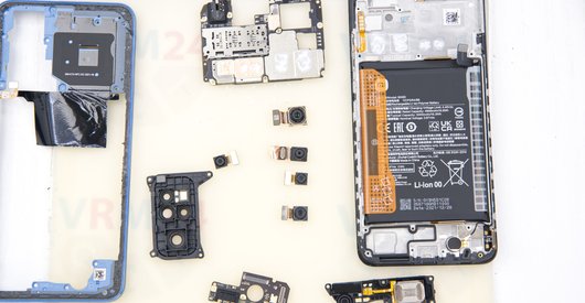
Pry up the connectors and remove the two rear cameras assembly.

If you have a question, ask us, and we will try to answer in as much detail as possible. If this article was helpful for you, please rate it.

81112
Views
37
Likes
—
Share
5
Questions
Related Instructions
Related Reviews
Related Blog
Popular Questions
G
Xiaomi Redmi Note 7
Unfortunately my Note 7 fell in the water and right now it's at the repair shop, I hope it can be fixed and I decided to watch this video to see how …
Gustavo Mendonça5
M
Xiaomi RedMi 5 Plus
Could i perform this without the glue? if not please tell me where to buy it
mZynths sam7
Xiaomi Redmi Note 11S
What is the actual length of coaxial cable?
dachou
J
Xiaomi RedMi Note 2 Prime
Data is deleted from the phone?
Javi Belda13
Xiaomi Pad 6
is there a insulation layer between the back case and the cpu?
alexander7Top instructions
Check our
Top Xiaomi instructions most liked by readers
New instructions
Check our
New Xiaomi brand instructions on vrm24.com