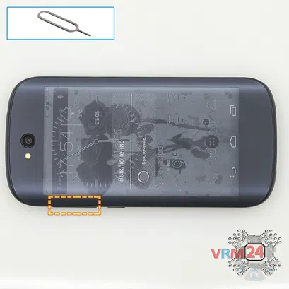

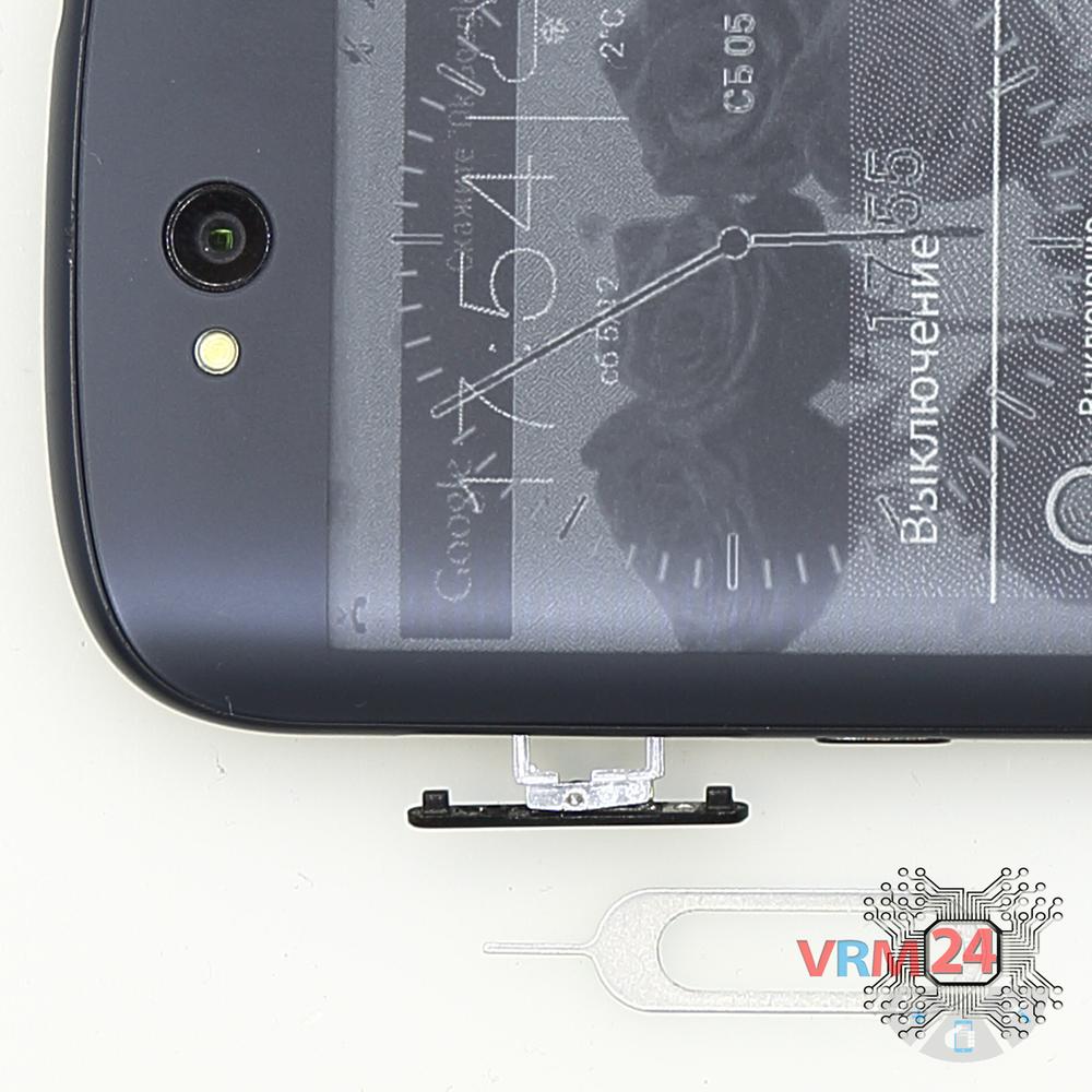
Use the ejection tool (aka Needle) or Paperclip. Push the tip all the way into the hole until the tray ejects, and then pull the tray of SIM card out.
Teardown difficulty:
Moderate
Moderate
Recommended tools


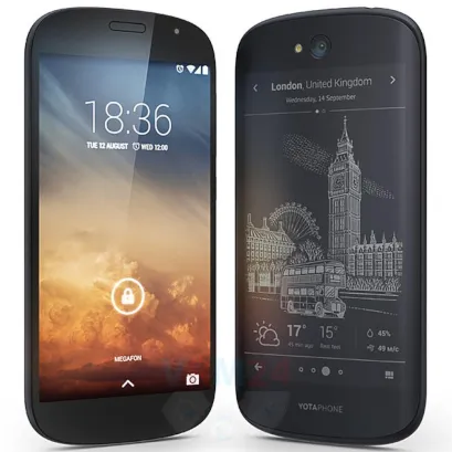
Disassembly/Repair of the mobile device Yota YotaPhone 2 YD201 (Yota YD201) with each step description and the required set of tools.

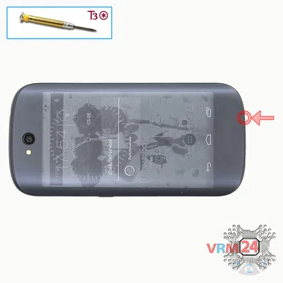

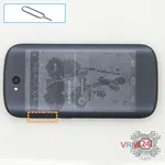
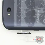
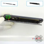
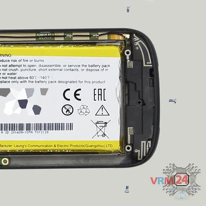
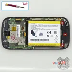
Step 2. Unscrew one screw
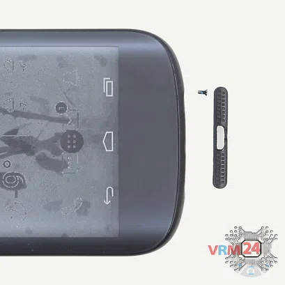
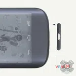
Unstick the cover at the end of the phone and remove it.
Using a screwdriver (hex T3), unscrew one screw.


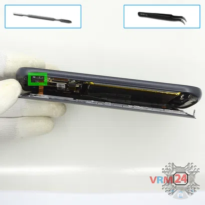
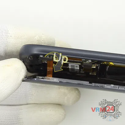
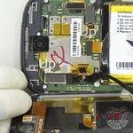
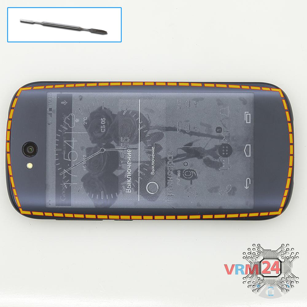
Step 3. Open the display module
⚠️️ Pay attention! Disassembly has a maximum 3rd difficulty because the process begins with the disassembly of the display module. If you have no experience or are not sure of your skills, we strongly recommend that you contact a specialized service center.
It will simplify the process. You can use a home hairdryer, but you will have to make a nozzle by hand or have a suitable one in the kit to gently heat and concentrate the heat flow in the right place.
ℹ️️ The surface of the display module must be heated to soften the adhesive underneath. The approximate heating temperature is 50° C / 125° F.
Use a thin plastic film or pick for separation. To facilitate the process, you can use isopropyl alcohol. It is often the most difficult to pass the tool between the parts to be divided. Choose the far edge from the FFC cables or buttons.
Do not use a lever or any force for separation that could damage the elements inside.
The process can be seen in our video entirely so as well as in detail, at the end of the instructions.

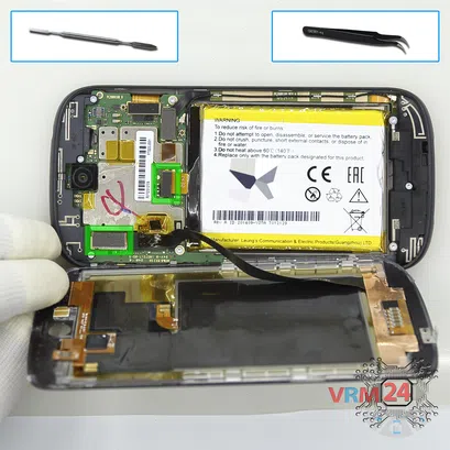
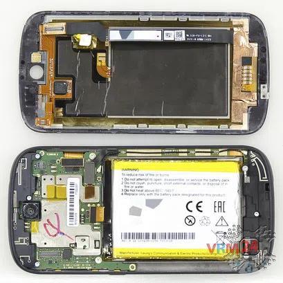
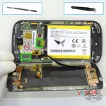
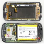
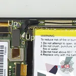
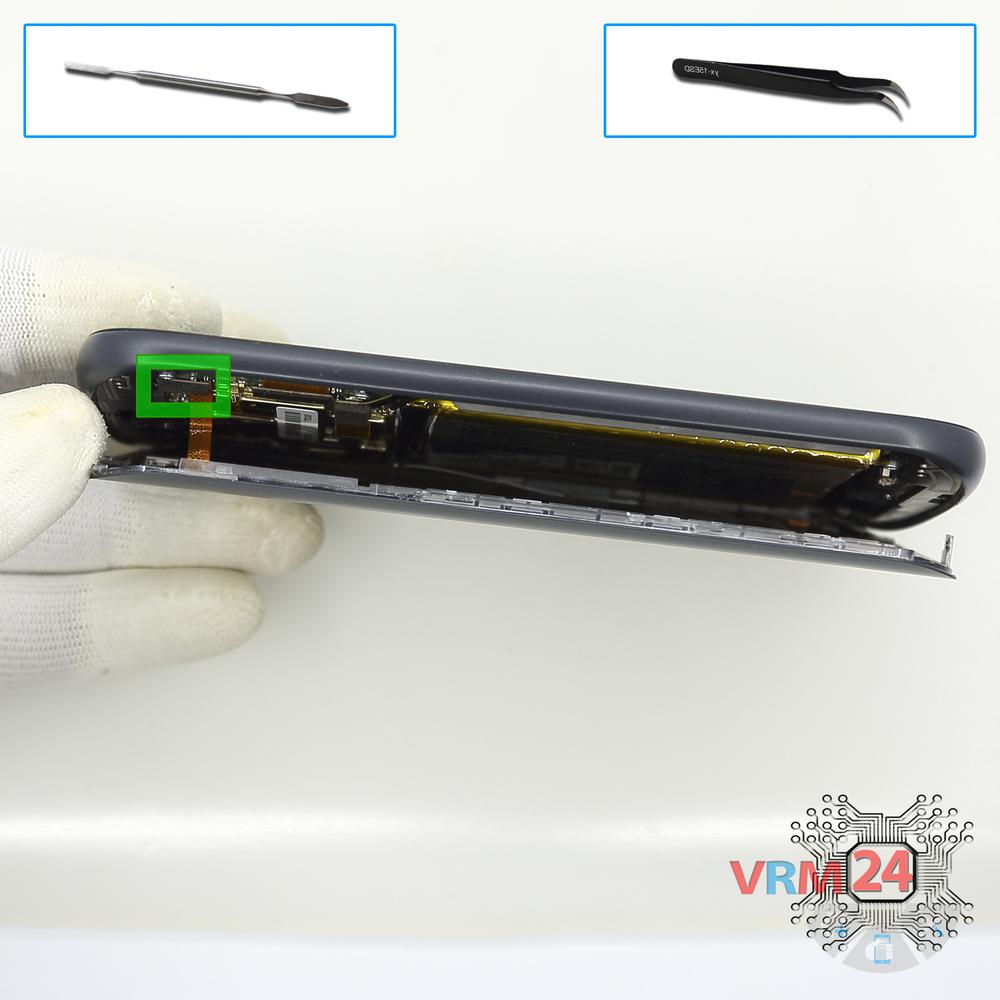
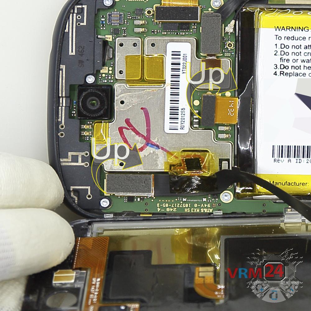
Step 5. Open the display module
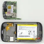
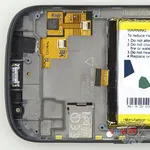
Open the cover-E-ink-display and disconnect the display cable connector on the motherboard and remove the back cover, also disconnect the battery connector.
⚠️️ Disconnect the battery connector as soon as possible. It is better to use a non-metal or plastic tool to avoid any damage.
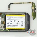
ℹ️️ The Yota YotaPhone 2 YD201 model has a battery YT0225023 with 2500 mAh capacity (aka rechargeable battery).
⚠️️ It is highly recommended to disconnect the connector to avoid possible short circuits during disassembly.


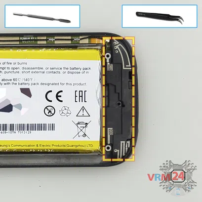
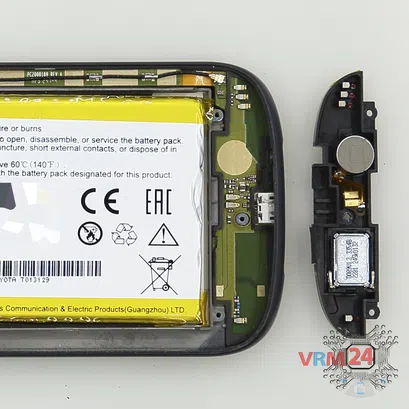
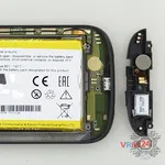
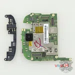
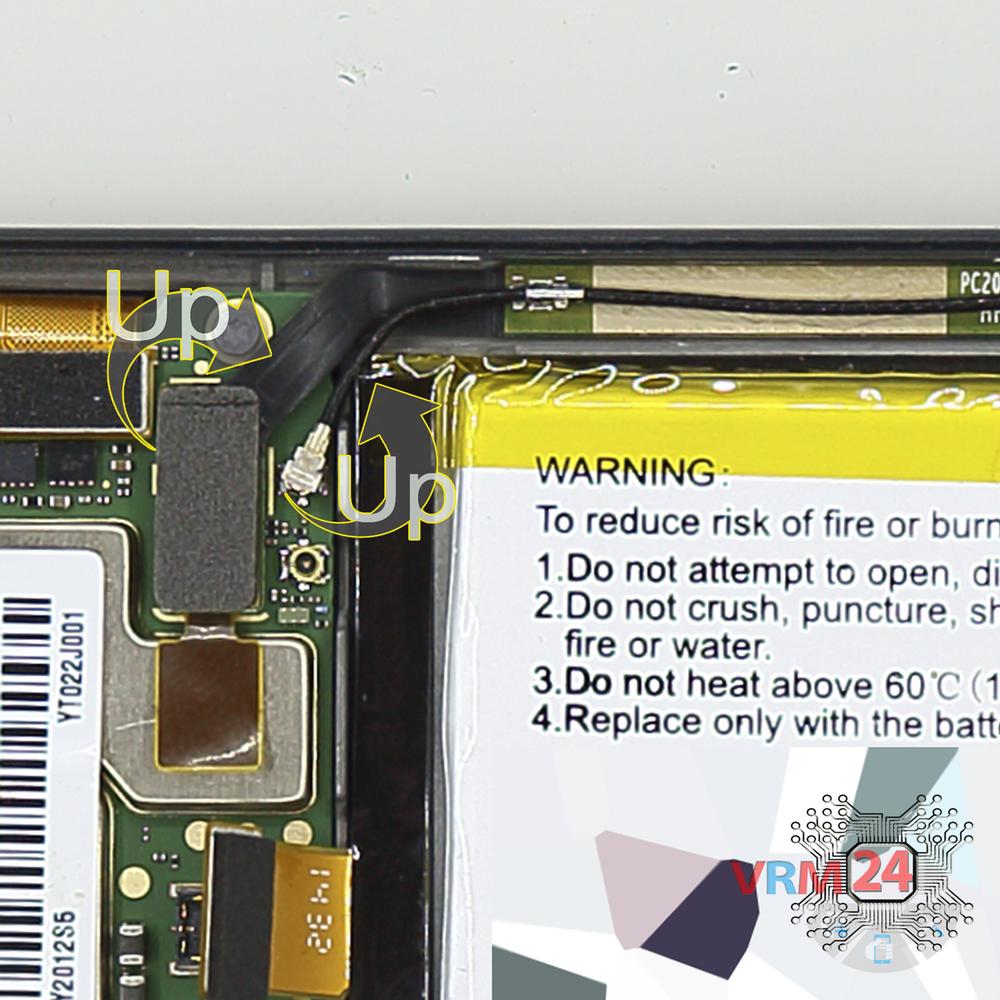
Step 7. Remove the loudspeaker
Pry over the edge and remove the assembly of the loudspeaker and vibration motor.


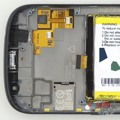
Step 8. Remove the sub-board
Disconnect the coaxial cable connector, inter-board sub-screen cable on the daughterboard.
Remove the sub-board. It may be glued to the frame with metalized tape, so to facilitate the process, the sub-board can be heated a bit.
The sub-board, also, may be attached with attachments like latches or hooks, be careful.
ℹ️️ The sub-board contains a charging port (Micro USB), microphone, inter-board cable, spring contacts for the speaker, vibration motor, and an antenna unit.
⚠️️ It is not necessary to insert the tool underneath when removing the sub-board. Internal components could be damaged.
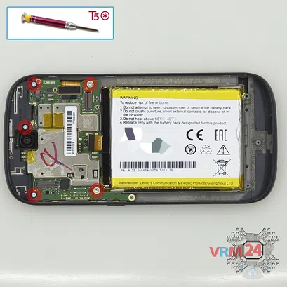


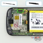
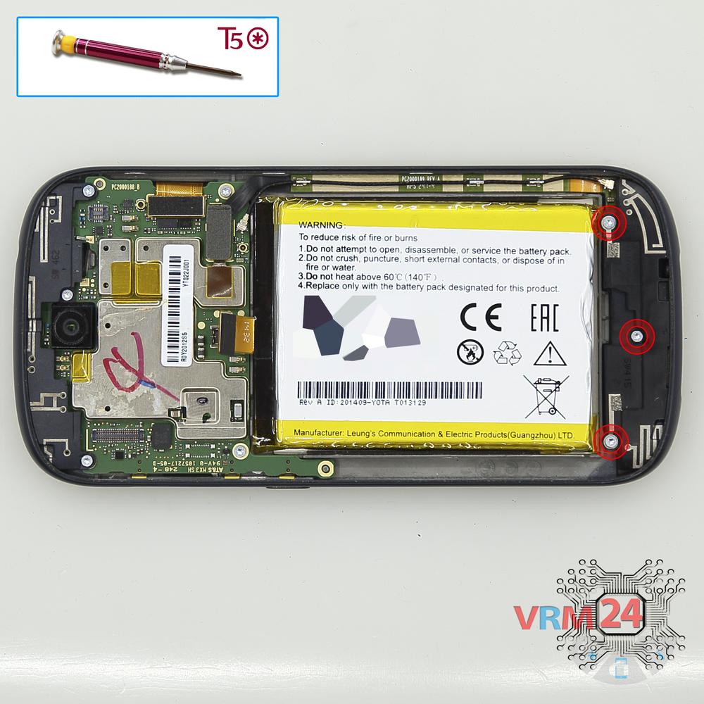
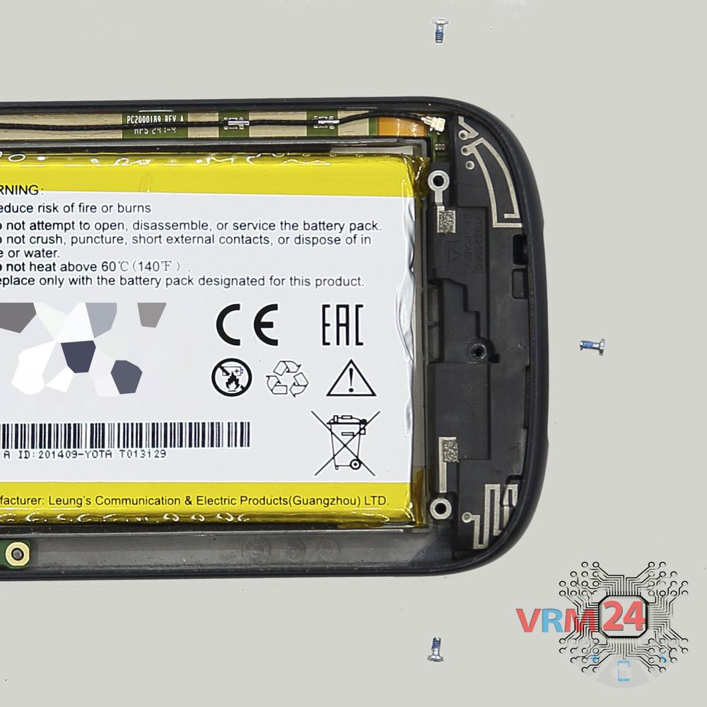
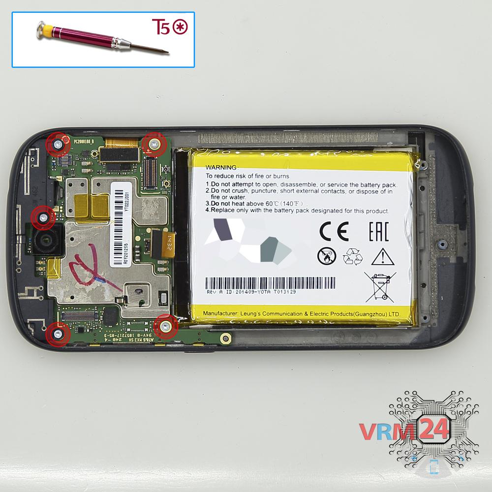
Step 9. Unscrew the screws
Using a screwdriver (hex T5), unscrew five screws securing the motherboard.
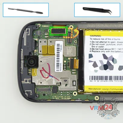
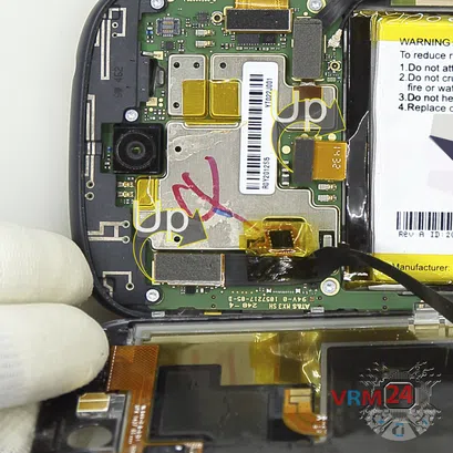
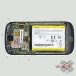
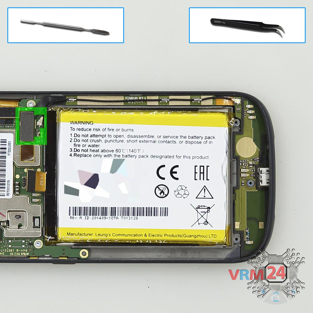
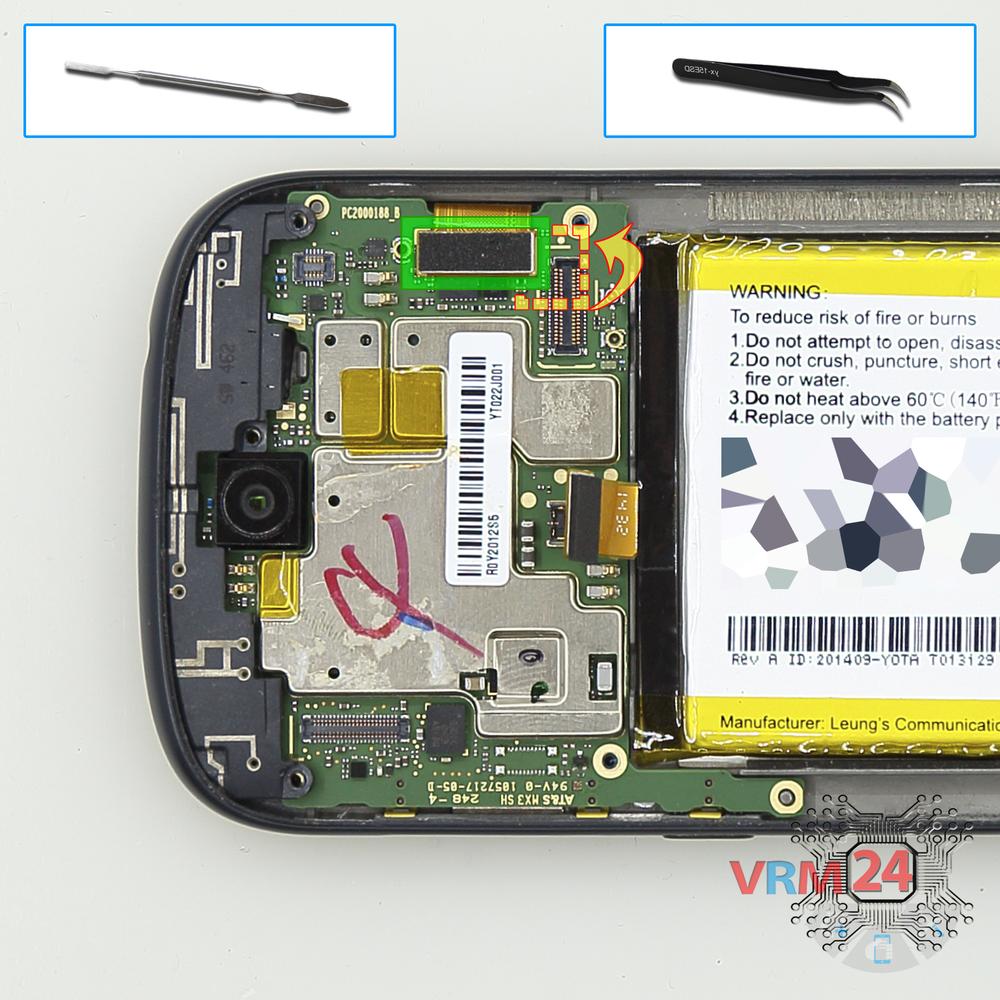
Step 10. Disconnect the connectors
Disconnect the display cable connector, and touchscreen cable connector from the inside of the motherboard.
⚠️️ Do not pull on the cable or pry it with a sharp tool, the connectors are pretty weak and break easily, or the cable falls out of the end (lug).
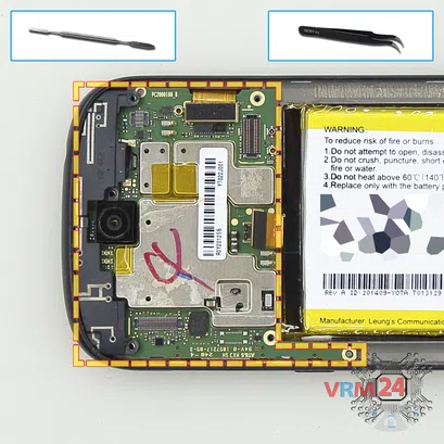
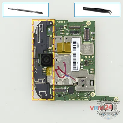
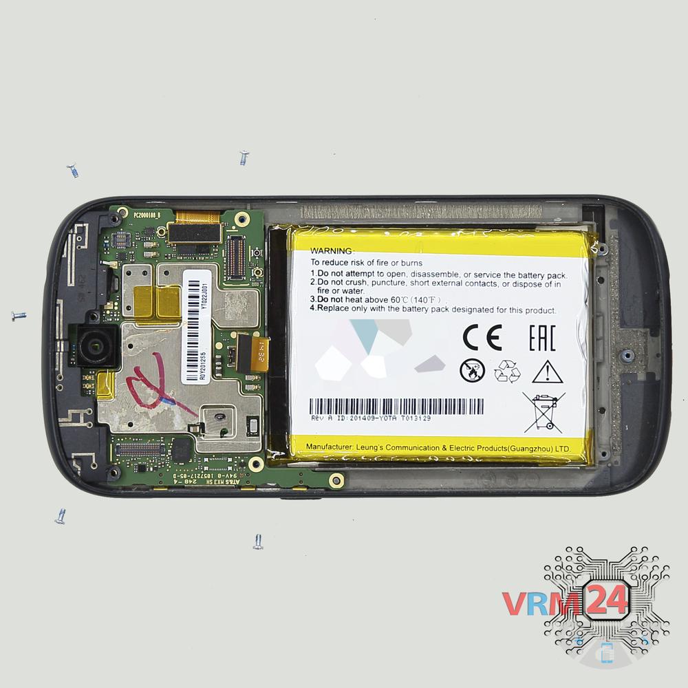
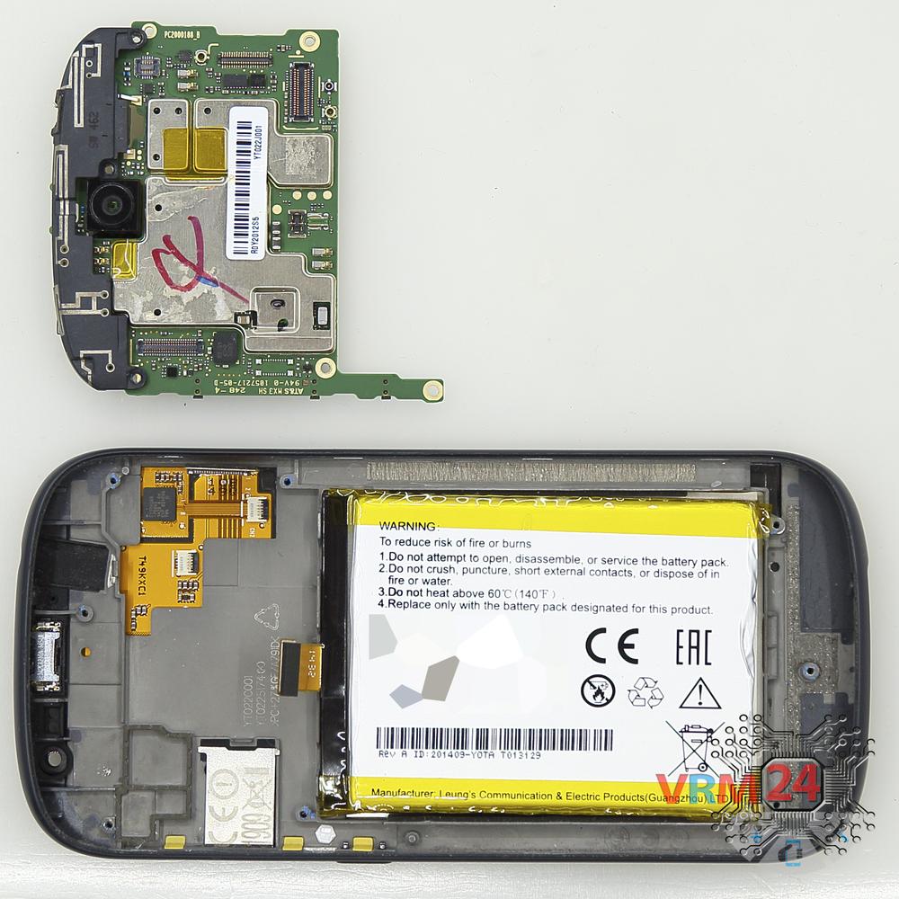
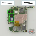
Step 11. Remove the motherboard
Carefully remove the printed circuit board. There is no need to use a lever or try to reach the circuit board by force. Make sure that nothing is getting in the way or holding the circuit board.
The motherboard, also, may be attached with attachments like latches or hooks, be careful.
⚠️️ Do not bend the circuit board when removing it or push tools under it. Unbeknownst to yourself, you can damage components or cables from the inside.
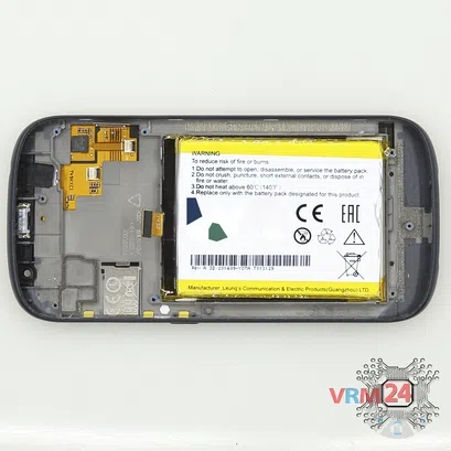

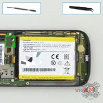
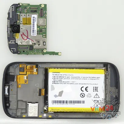
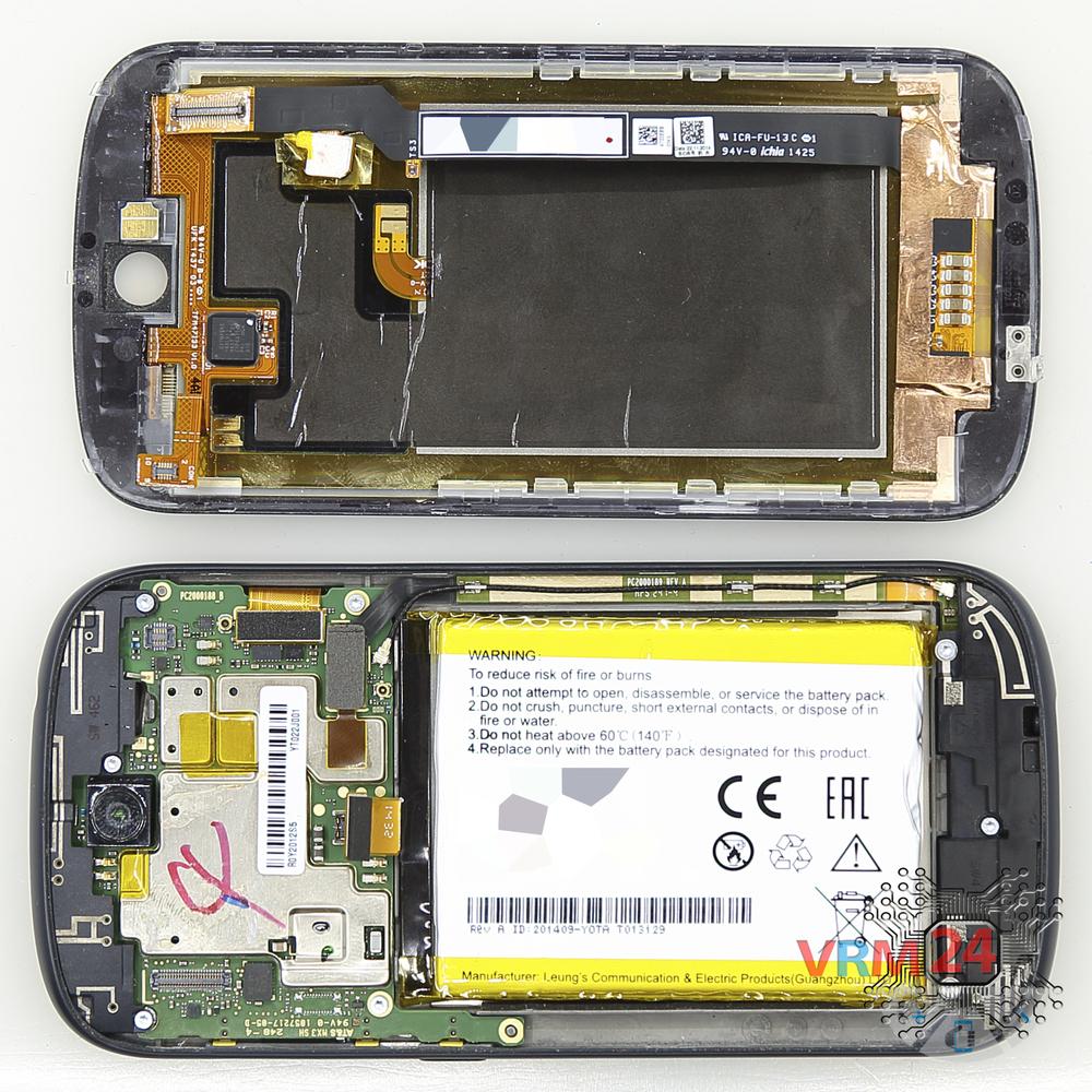
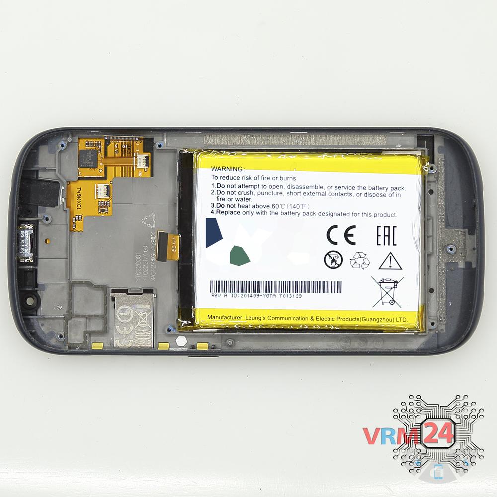
Step 12. In the display frame remained
ℹ️️ In the display frame remained: the earpiece speaker, battery.
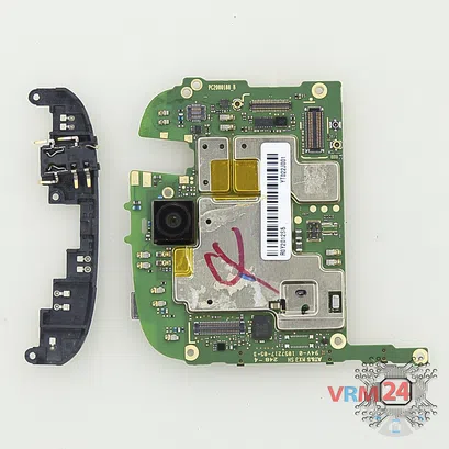
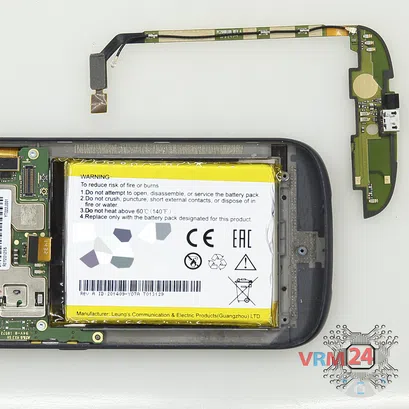
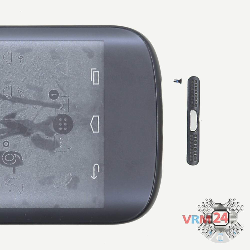
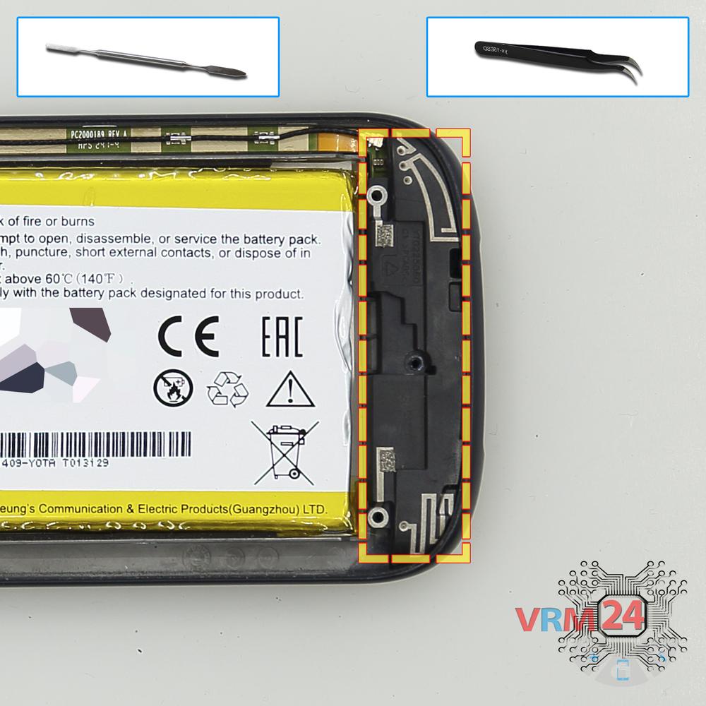
Step 13. Remove the headphone port
Pry over the edge and remove the cover with the headphone jack socket and antenna tracks and pads.

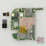
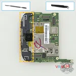
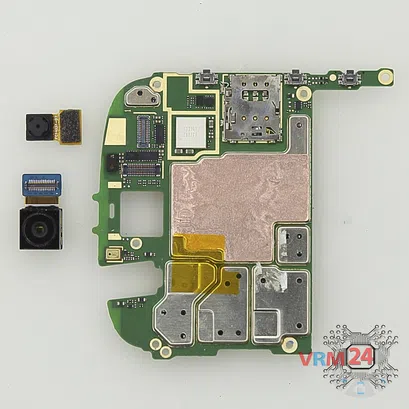
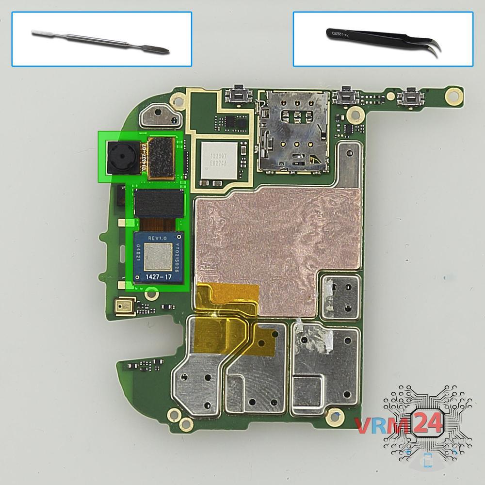
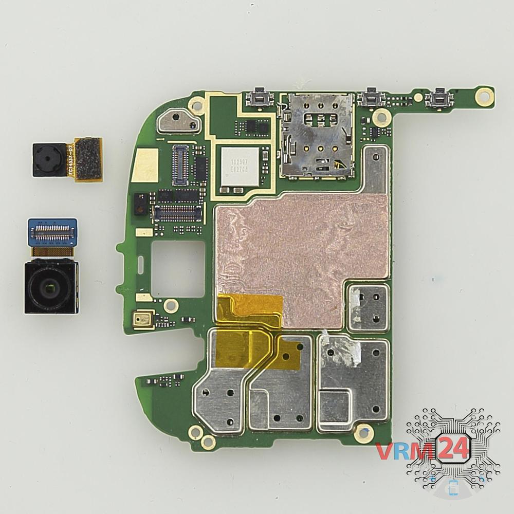
Step 14. Remove the cameras
Disconnect connectors on the motherboard and remove one rear camera and one front (selfie) camera.
Detailed disassembly instructions of Yota YotaPhone 2 YD201 in the video, made by our mobile repair & service center:
If you have a question, ask us, and we will try to answer in as much detail as possible. If this article was helpful for you, please rate it.

Disassembling\Repair has medium complexity and takes about 8 minutes in time.
Our manual is suitable for all models Yota YotaPhone 2 YD201 — Yota YD201 released for markets in different countries.
Back to the list