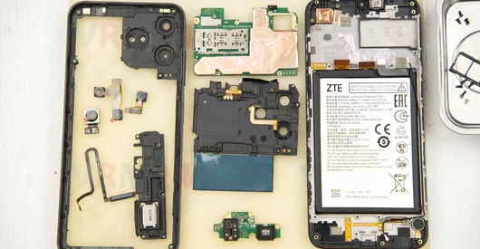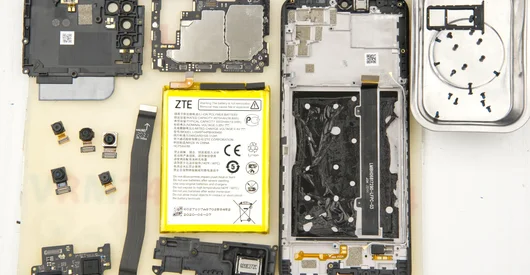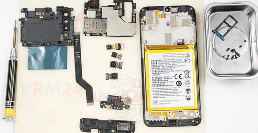

Recommended tools
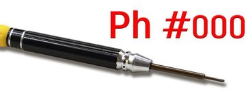
Screwdriver Phillips #000
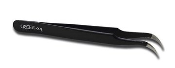
Tweezers
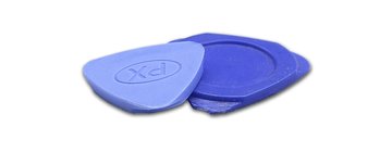
Non-metallic tool
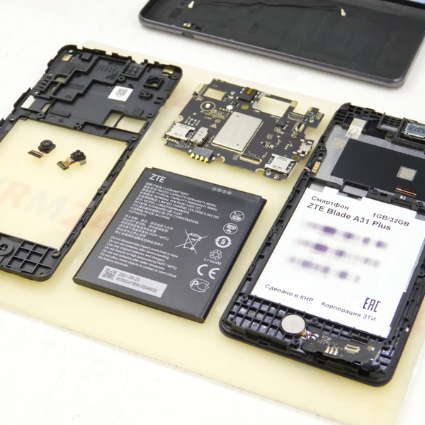
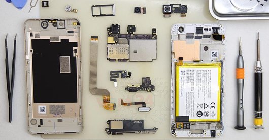
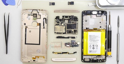
Disassembly/Repair of the mobile device ZTE Blade A31 Plus with each step description and the required set of tools.
4099
Views
6
Likes
—
Share
0
Questions

Step 1.
Before disassembling!
⚠️ Before disassembling, do not forget to turn your phone off.
Step 2.
Open the back cover
First of all, we do not need to remove the card tray and therefore we go straight to the back cover detachment - because we do not have a card tray.
We carefully go along the edge detaching the clips and the back cover itself.
Step 3.
Remove the battery
And we need to remove the battery.
There is an indentation at the end of the battery on the middle cover. Hook the battery at this point, lift it up and remove the battery.
Step 4.
Unscrew the screws
Then we move on to unscrewing the eighteen screws in the upper and lower parts. For this we use a Phillips screwdriver one and a half millimeters or Philips #000.
Carefully unscrew the screws, we place them on a special surface. It looks like all the screws are the same, but just in case they can be arranged in a certain order.
Step 5.
Open the mid-frame
We move on to detach the middle cover.
To remove the middle cover, it is better to use tweezers, because this type of cover is held not by clips, but rather by plastic hooks. Therefore, it is more convenient to pry and detach this type of fixation - with tweezers.
Step 6.
Remove the coaxial cable
We disconnect coaxial cable connectors on both boards and remove the coaxial cable.
Step 7.
Disconnect the connector
Disconnect the underscreen cable connector on the sub-board.
Step 8.
Remove the sub-board
And we can carefully detach the sub-board which is taped to the display frame.
We gently pry up the edges, rock it slightly and remove the sub-board. If we want to change the sub-board, we need to unsolder the wires of the vibration motor.
Step 9.
Remove the cameras
We move on to detach the cameras.
The rear camera has an unusual type of connector with a lock.
First, we need to release the lock and then we need to pull out the rear camera cable.
So we unclip the locks on the connector and pull the cable out of the connector and remove the rear camera.
For the front camera - we peel off the thermal dissipating tape and detach the camera itself and also carefully put it aside.
Step 10.
Disconnect the connectors
Then we move on to disconnecting the connectors of the display cable and underscreen cable.
This type of connector has a lock. First, we need to release the lock and then we need to pull out the cable.
Step 11.
Remove the motherboard
Next, we move on to detaching the motherboard. As always, we need to find the right spot that we can hook and gently lift and remove the motherboard without too much effort.
⚠️ Do not bend the circuit board when removing it or push tools under it. Unbeknownst to yourself, you can damage components or cables from the inside.
Step 12.
In the display frame remained
ℹ️ In the display frame remained: the earpiece speaker, vibration motor, and sub-board.

If you have a question, ask us, and we will try to answer in as much detail as possible. If this article was helpful for you, please rate it.

4099
Views
6
Likes
—
Share
0
Questions
Related Instructions
Related Reviews
Related Blog
Top instructions
Check our
Top ZTE instructions most liked by readers
New instructions
Check our
New ZTE brand instructions on vrm24.com