⚠️️ Before disassembling, do not forget to turn your phone off.
Teardown difficulty:
Moderate
Moderate
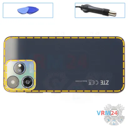
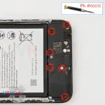
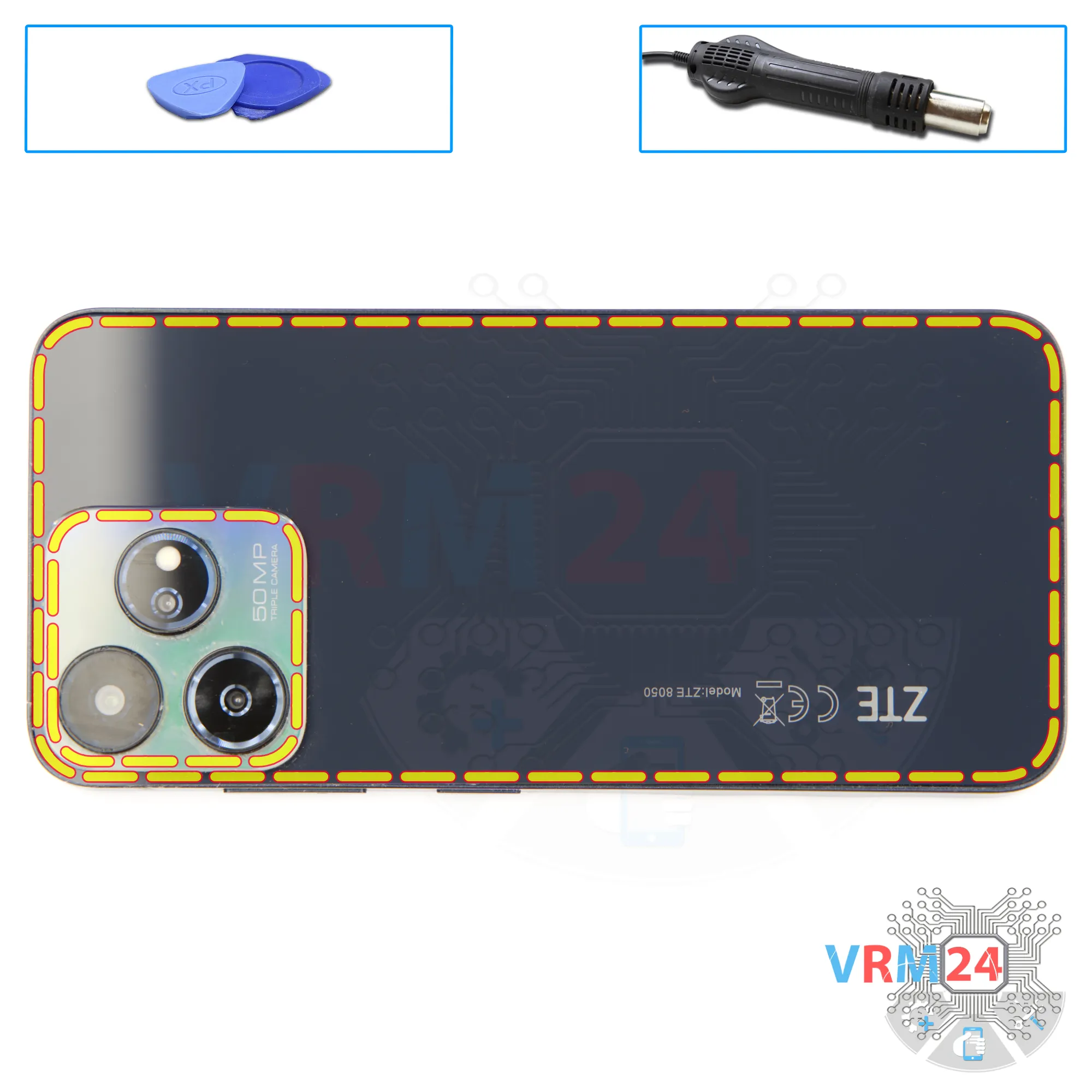
Recommended tools


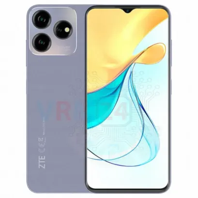
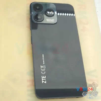
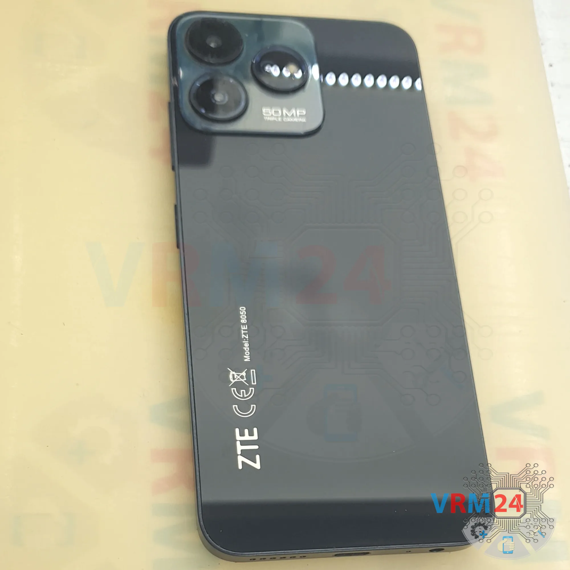
Disassembly/Repair of the mobile device ZTE Blade V50 Design (ZTE Blade V50 Design ZTE 8050) with each step description and the required set of tools.

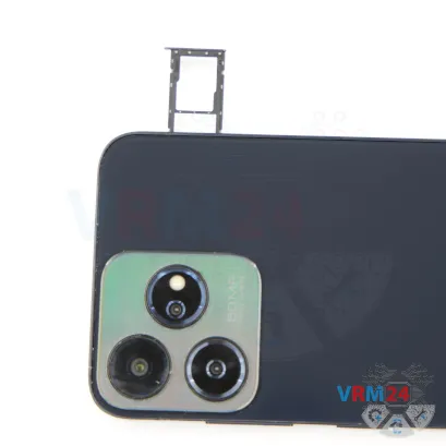
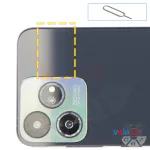
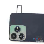

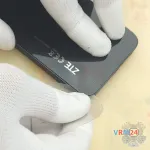
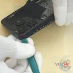
Step 2. Remove the tray
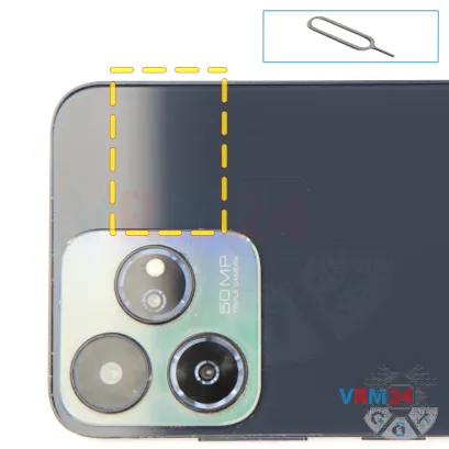
First of all, we need to remove the SIM card tray.
For this, we’ll use a special eject tool.
Insert it into the hole and carefully push the tray out.
If the tray doesn’t come out smoothly, we can also use tweezers to help pull it out.

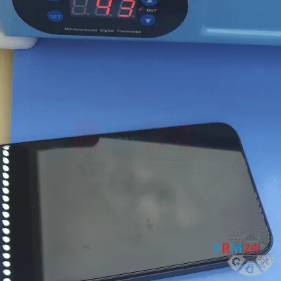


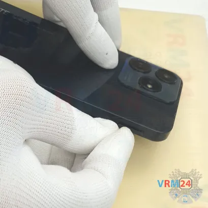
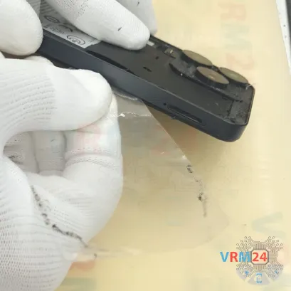
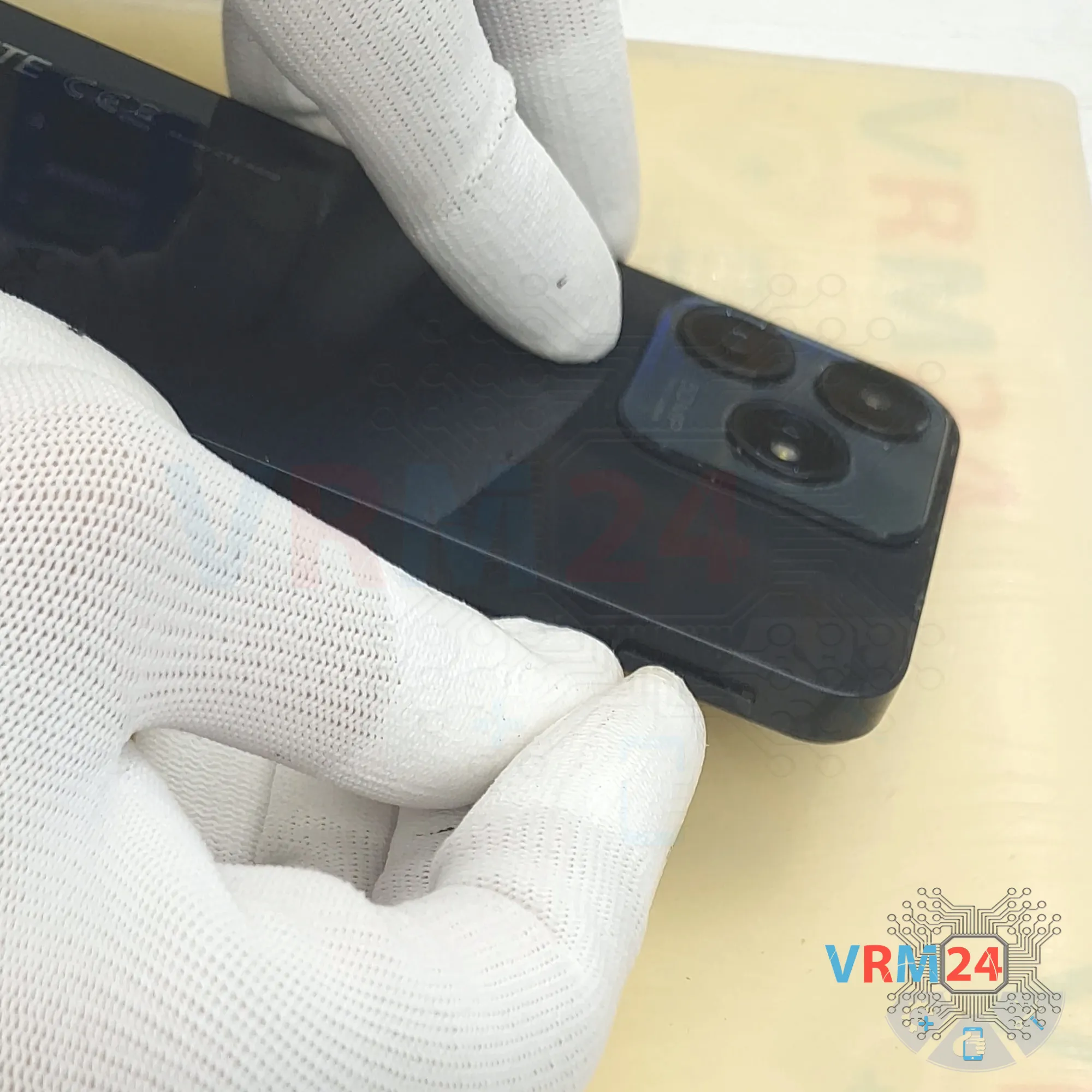
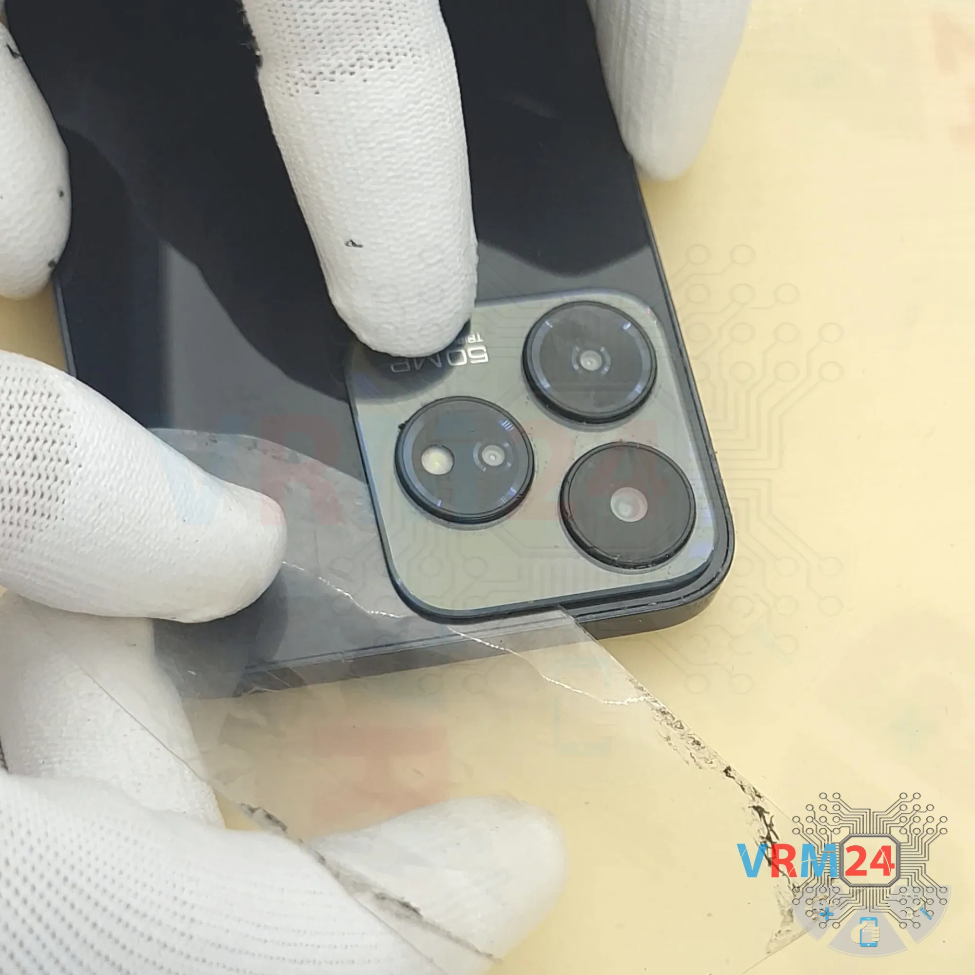
Step 3. Open the back cover
Next, we need to heat the back cover to about 70 degrees Celsius or 160 degrees Fahrenheit. For this, we’ll use a heating pad, but you can also use a heat gun or hairdryer.
Take note: on this model, the back cover is additionally glued down in the camera area. That means we also need to heat that section to make separation easier.
Now let’s move on to removing the back cover. For this, we use a thin plastic film, sliding it into the gap between the back cover and the midframe, and carefully working our way around the edge to slice through the adhesive.
Go slowly along the edge—don’t push the film too deep under the cover, since we don’t know exactly what components may be underneath.
After going all the way around, we’ll try to peel the back cover off near the camera section. Using the thin plastic film, carefully loosen the adhesive in this spot.
The cover here is glued down very firmly, so extra caution is needed.
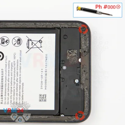
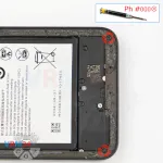

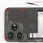
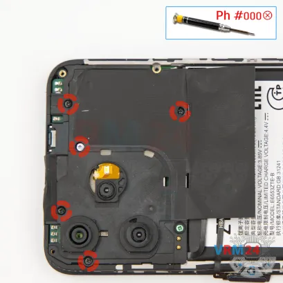
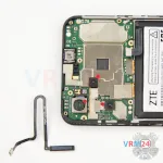
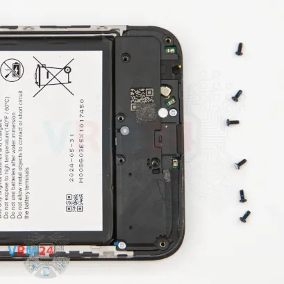
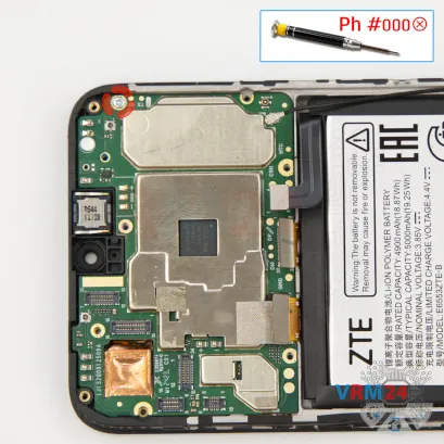
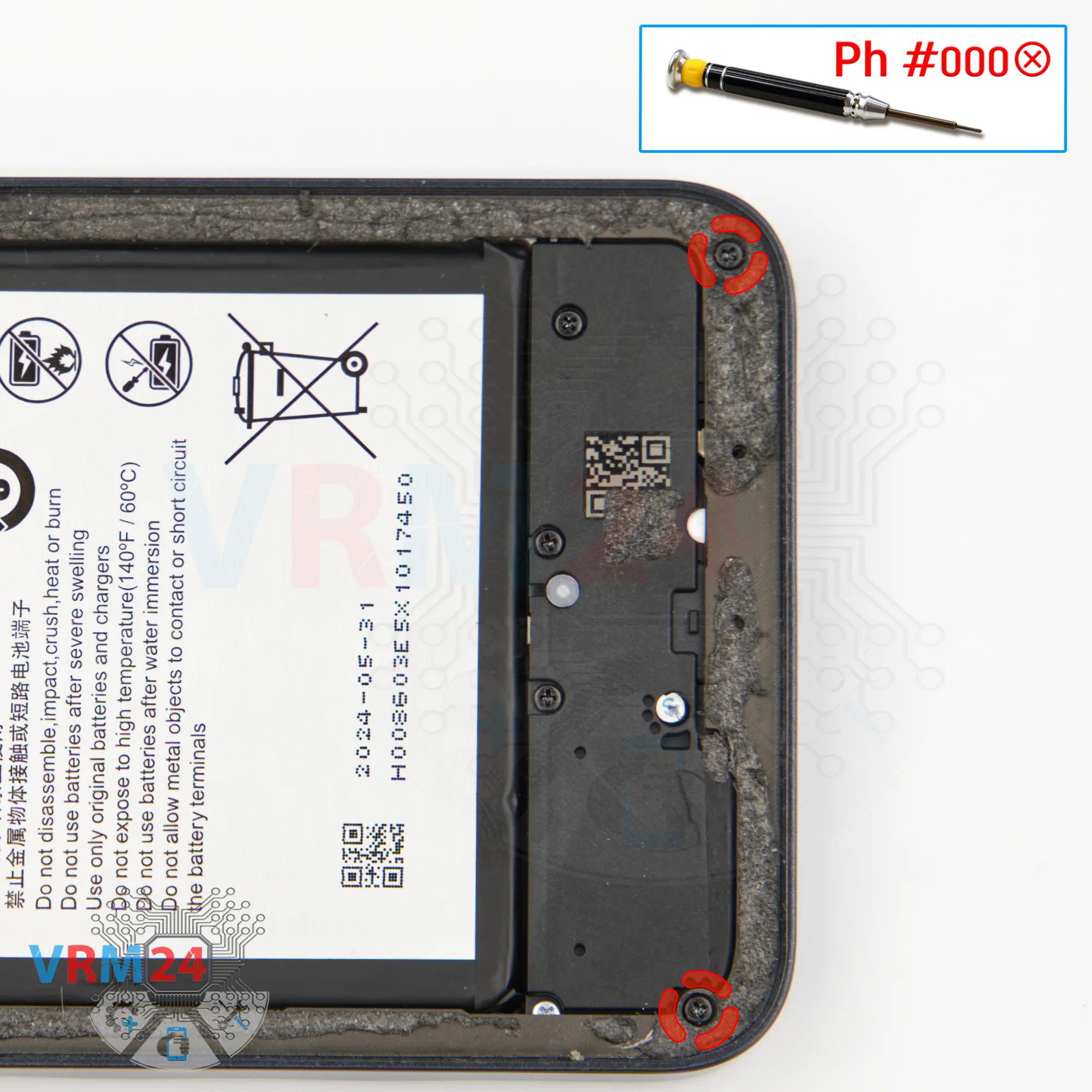
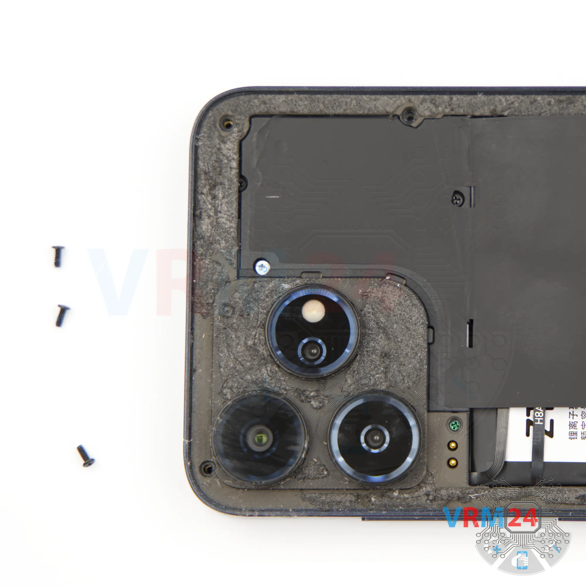
Step 4. Unscrew the screws
Next, we need to remove the screws.
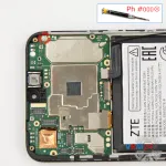
For this, we’ll use a 1.5 mm Phillips screwdriver or a Phillips #000. These screws secure the midframe.
Unscrew them carefully and place them on a dedicated surface in an organized layout, since the screws may vary in size.
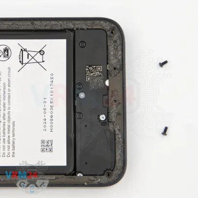
First, we unscrew the two screws at the bottom.


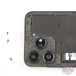
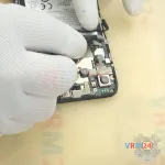
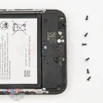
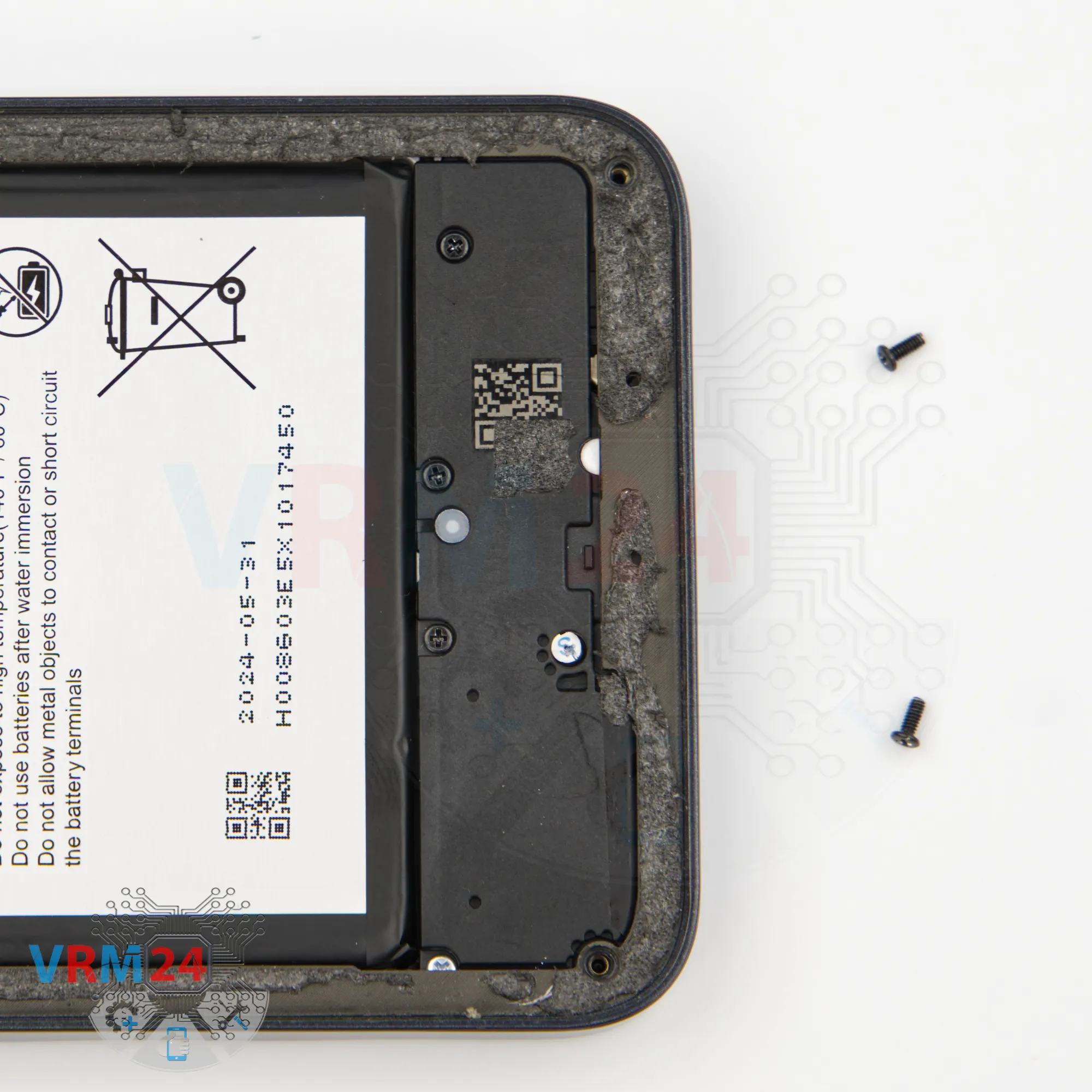
Step 5. Unscrew the screws
Using a screwdriver Phillips 1.5 mm (PH #000), unscrew the three black screws at the top.

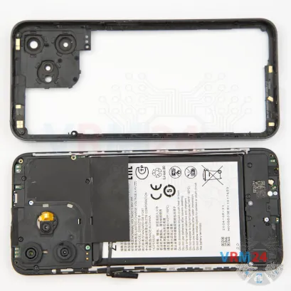


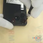
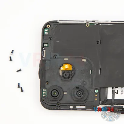
Step 6. Open the mid-frame
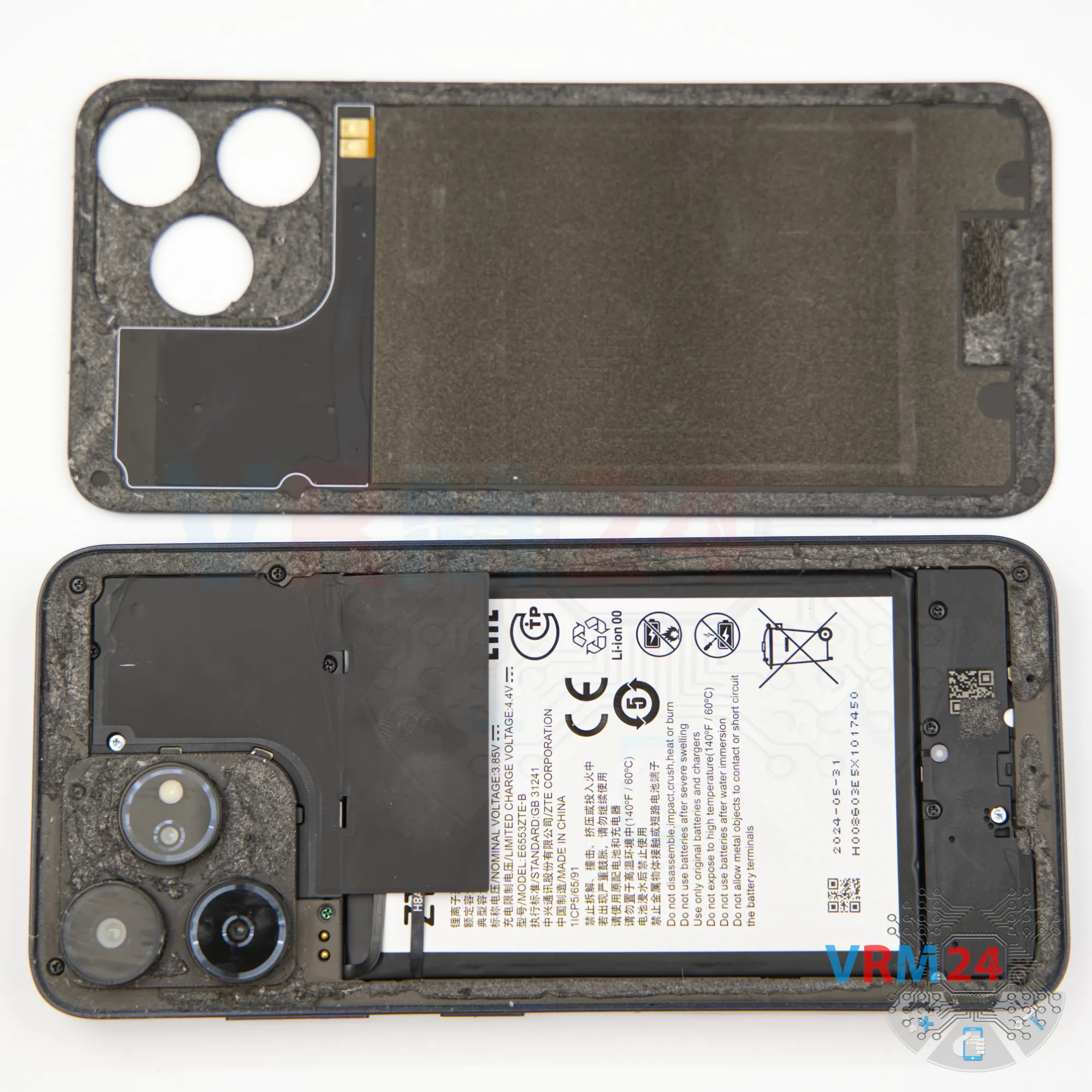
Now we move on to removing the midframe.
We start with a thin plastic film, unclipping a few catches near the SIM tray slot, then switch to a sturdier tool.
On this model, the midframe is also held in place pretty tightly, so we need to be careful. Don’t force it, otherwise we could damage the edge of the display.
In our case, the fingerprint sensor just falls out—it’s not secured to the midframe.
At this point, it’s best to cover the camera lenses. For this, we use a protective film.
Note that we stick the film onto the rim around the lenses, not directly on the glass.
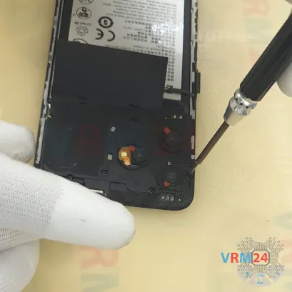

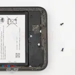
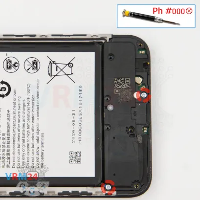
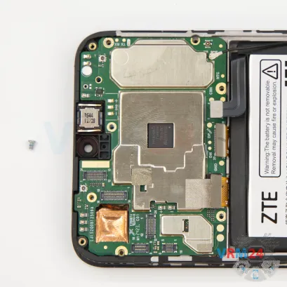
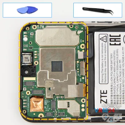
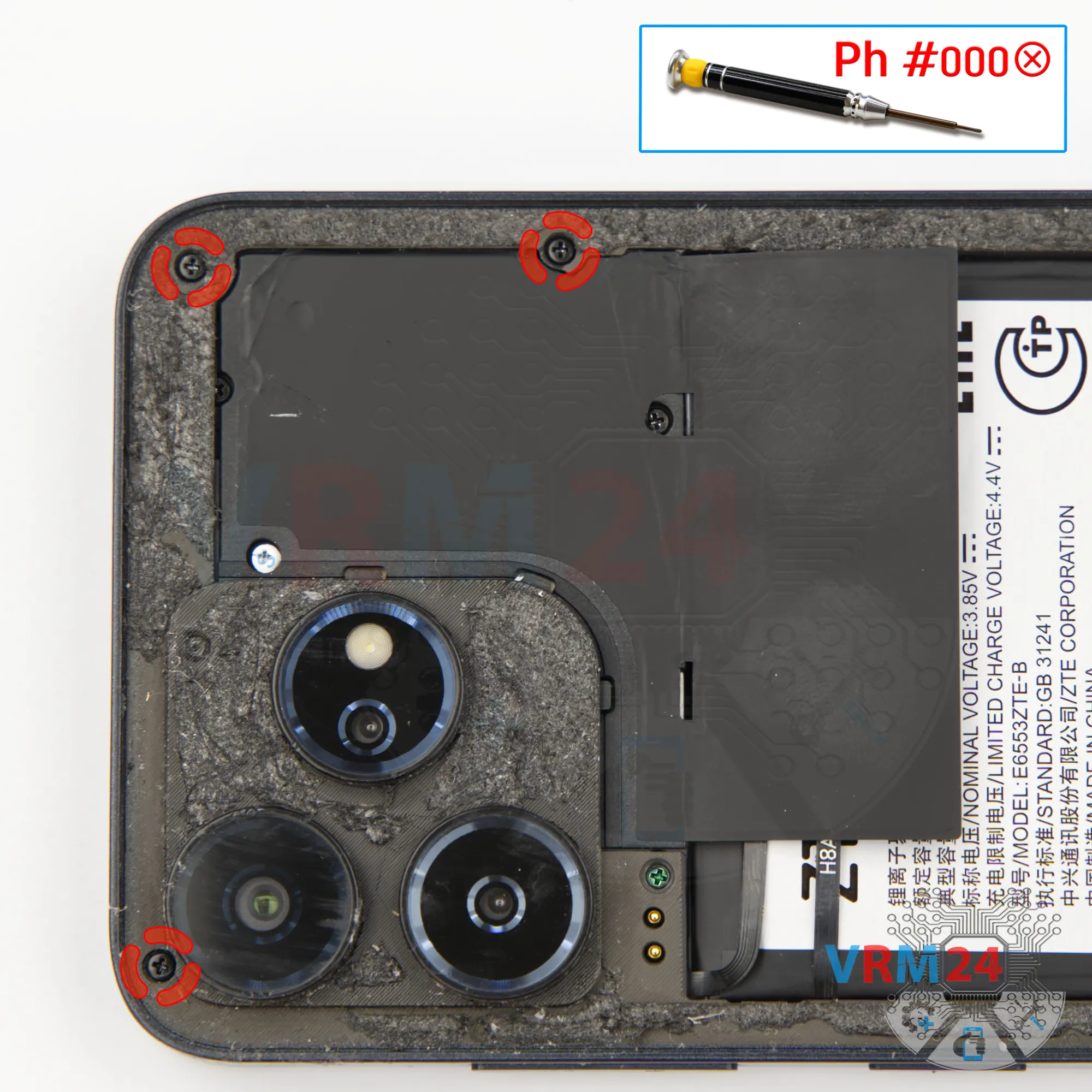
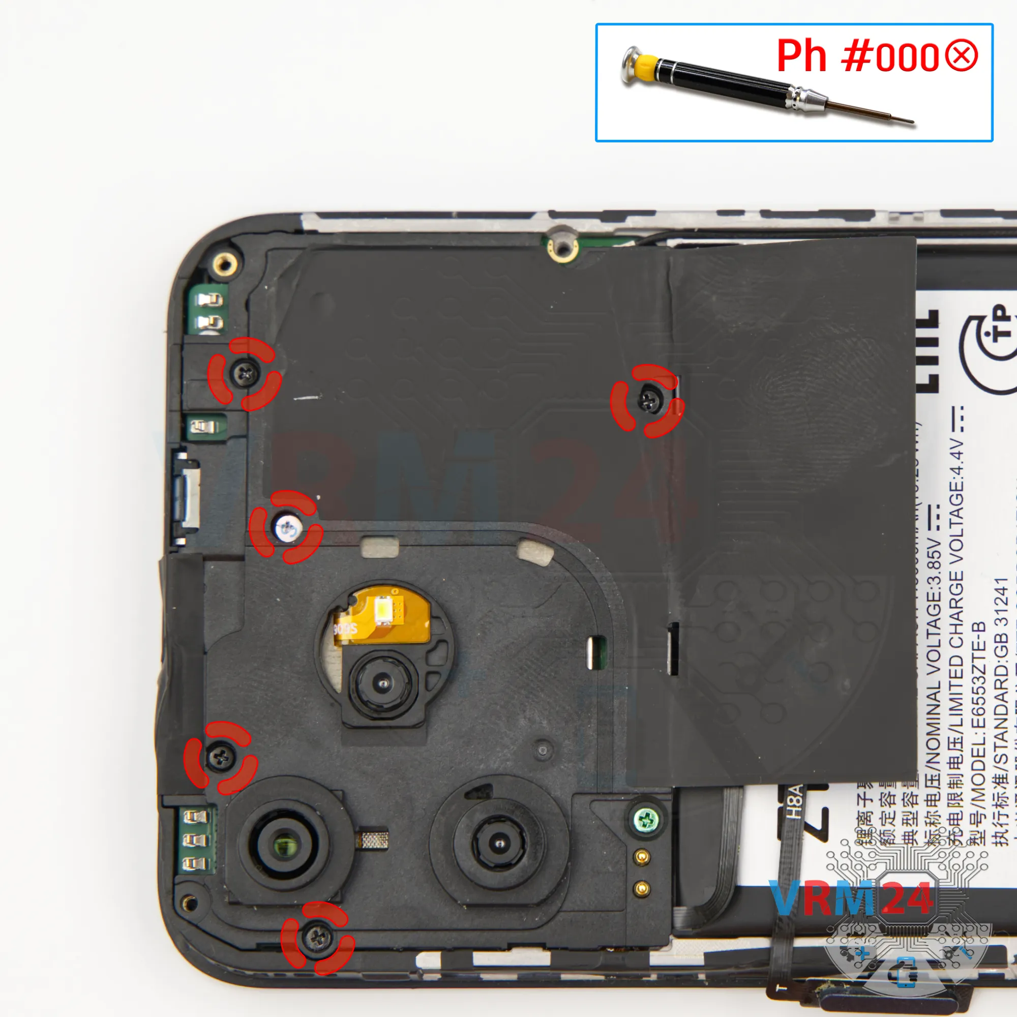
Step 7. Unscrew the screws
Using a screwdriver Phillips 1.5 mm (PH #000), unscrew the five short screws.

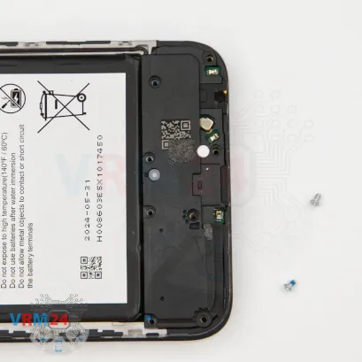
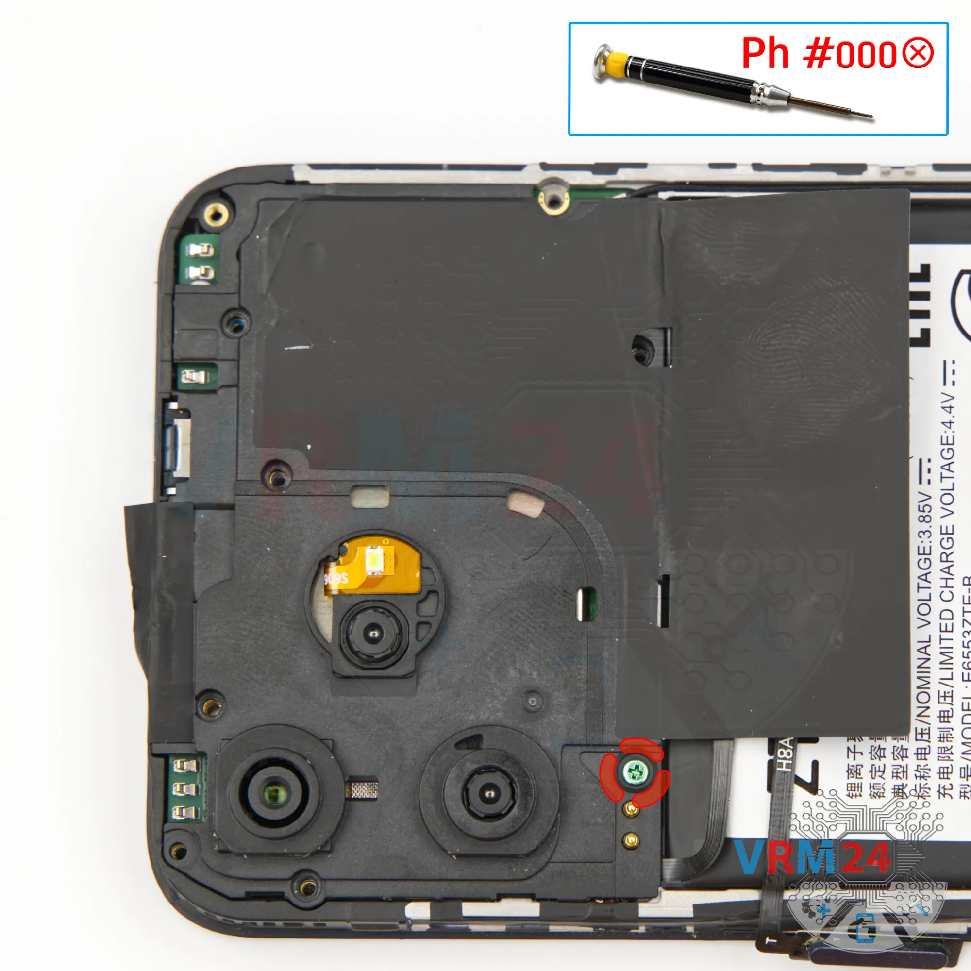
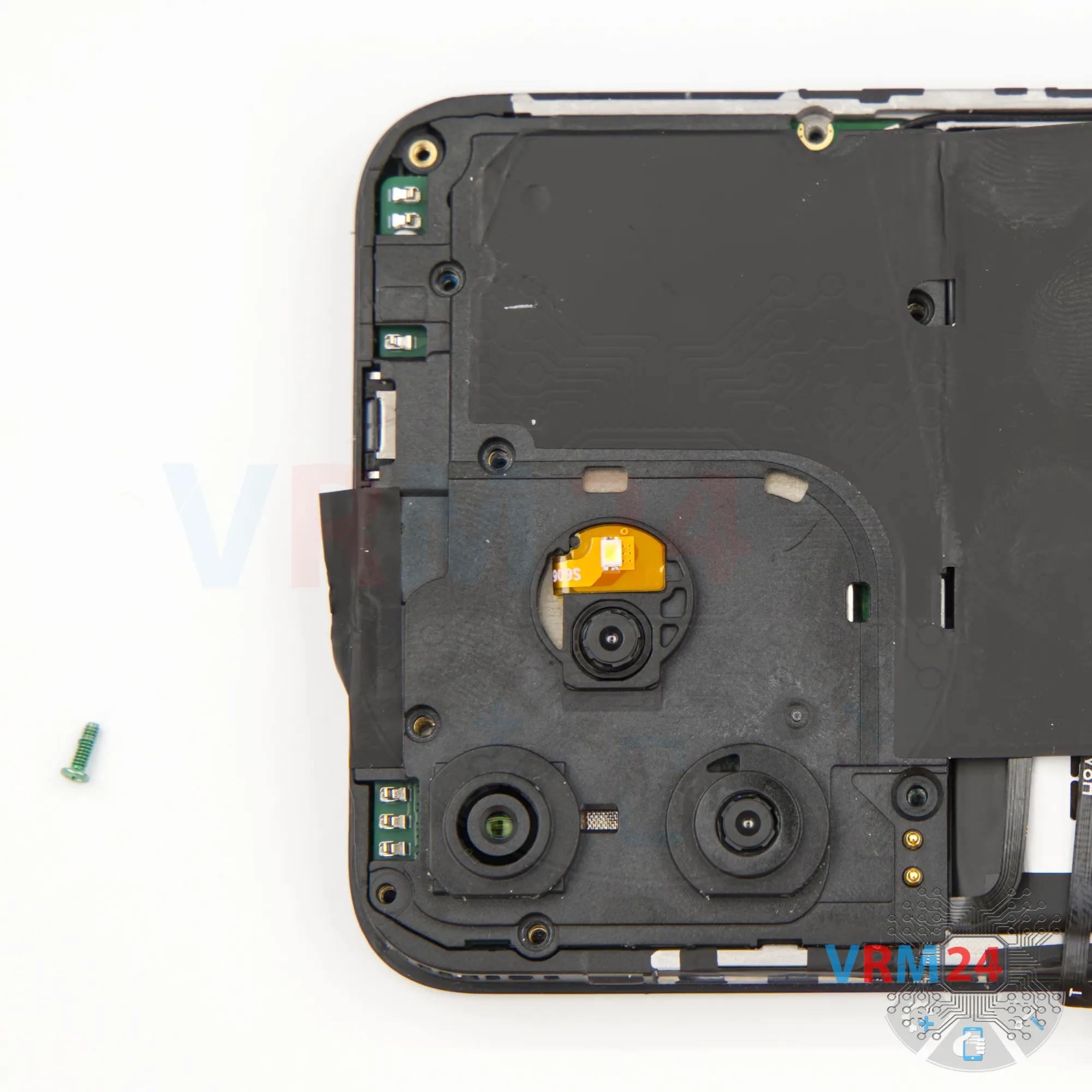
Step 8. Unscrew one screw
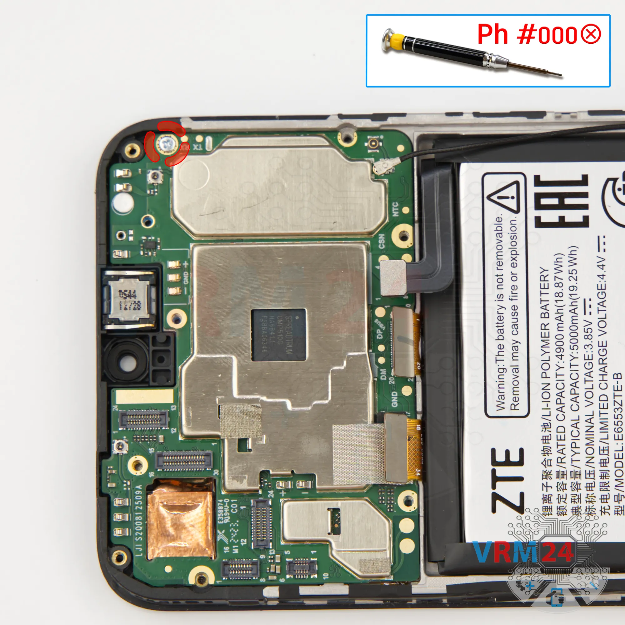
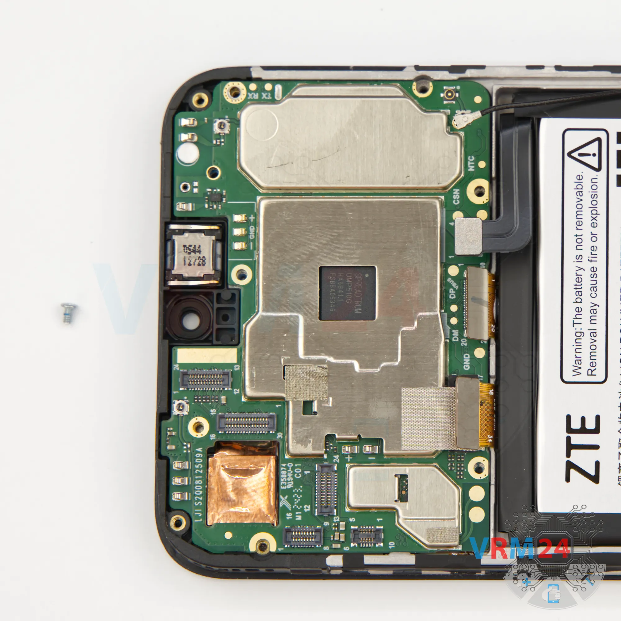
Using a screwdriver Phillips 1.5 mm (PH #000), unscrew the one silver screw.

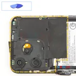

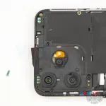
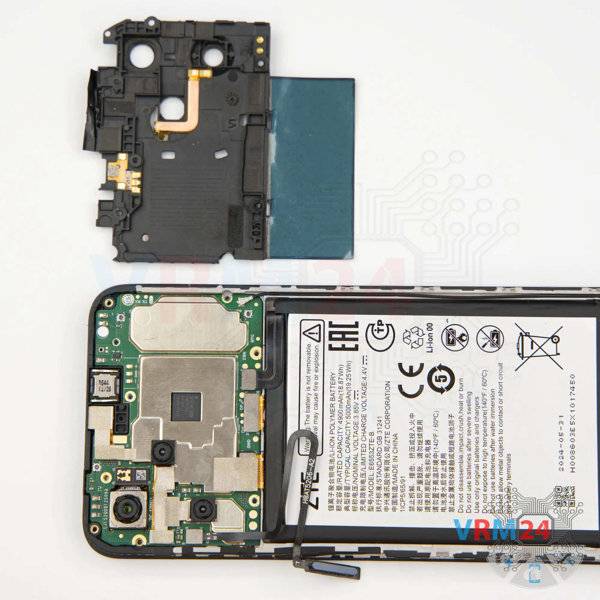
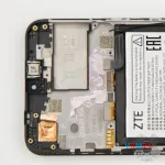
Step 9. Open the cover
Next, using a non-metal tool, we need to remove the cover.
Carefully pry it up at the edge, unclip the catches, and lift off the cover that protects the motherboard.
It may have a little adhesive at the top. Set it aside.
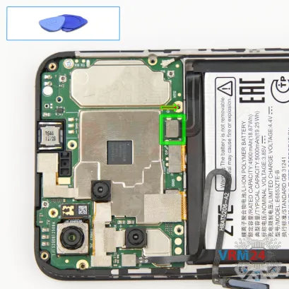

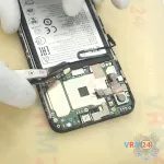
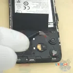
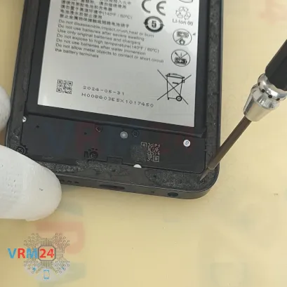
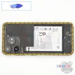
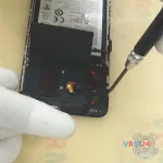
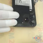
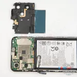
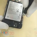
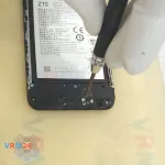
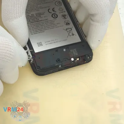
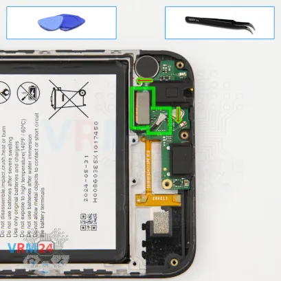
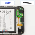
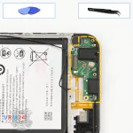
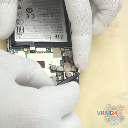
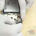
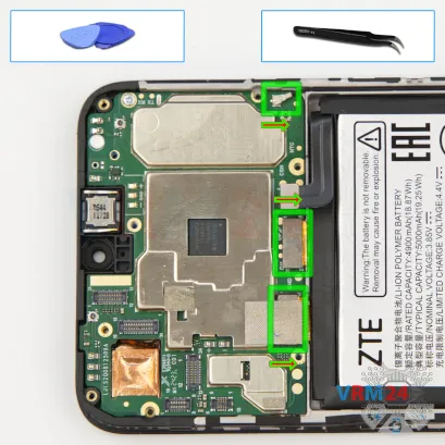
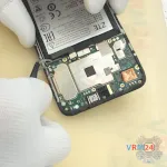
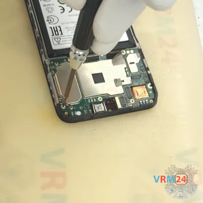
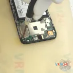
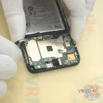
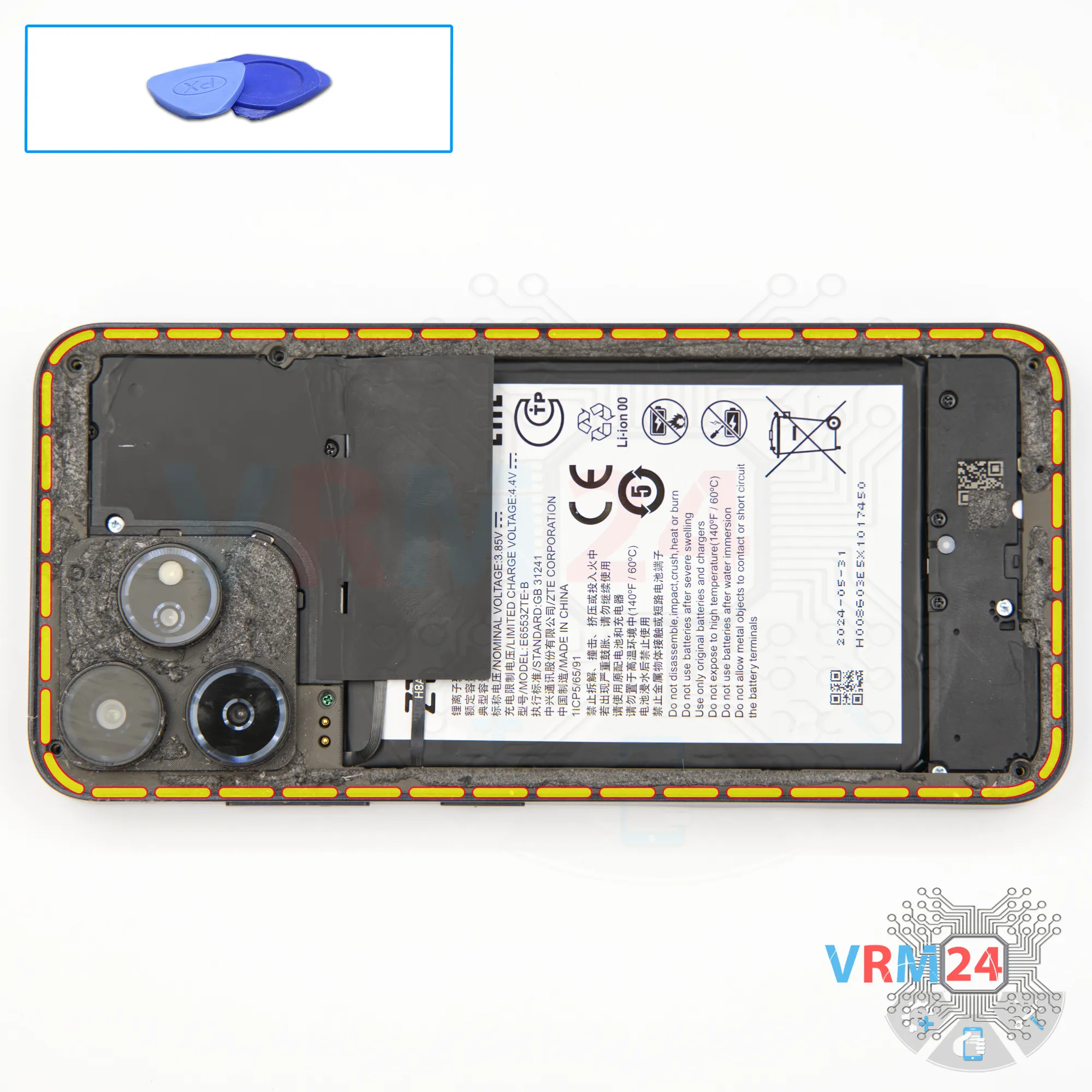
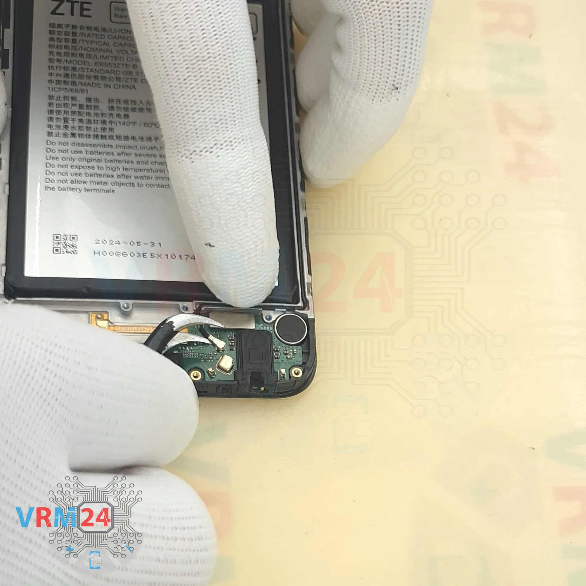
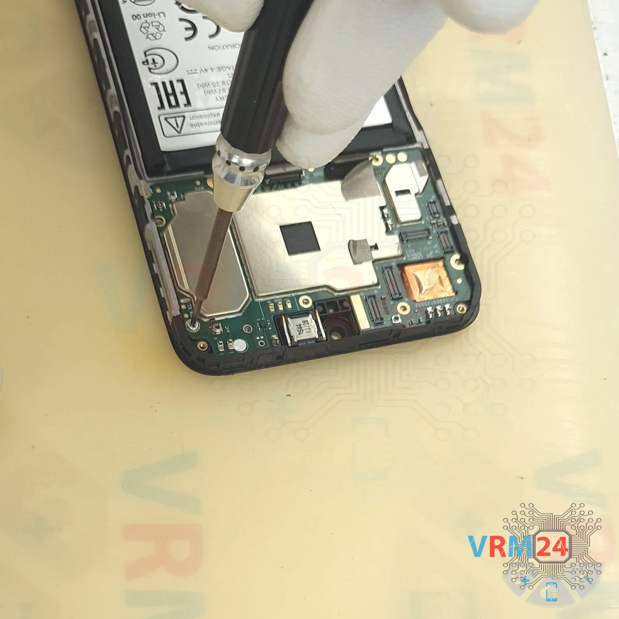
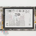
Step 10. Disconnect the battery connector
Then, using a non-metal tool, disconnect the battery connector.
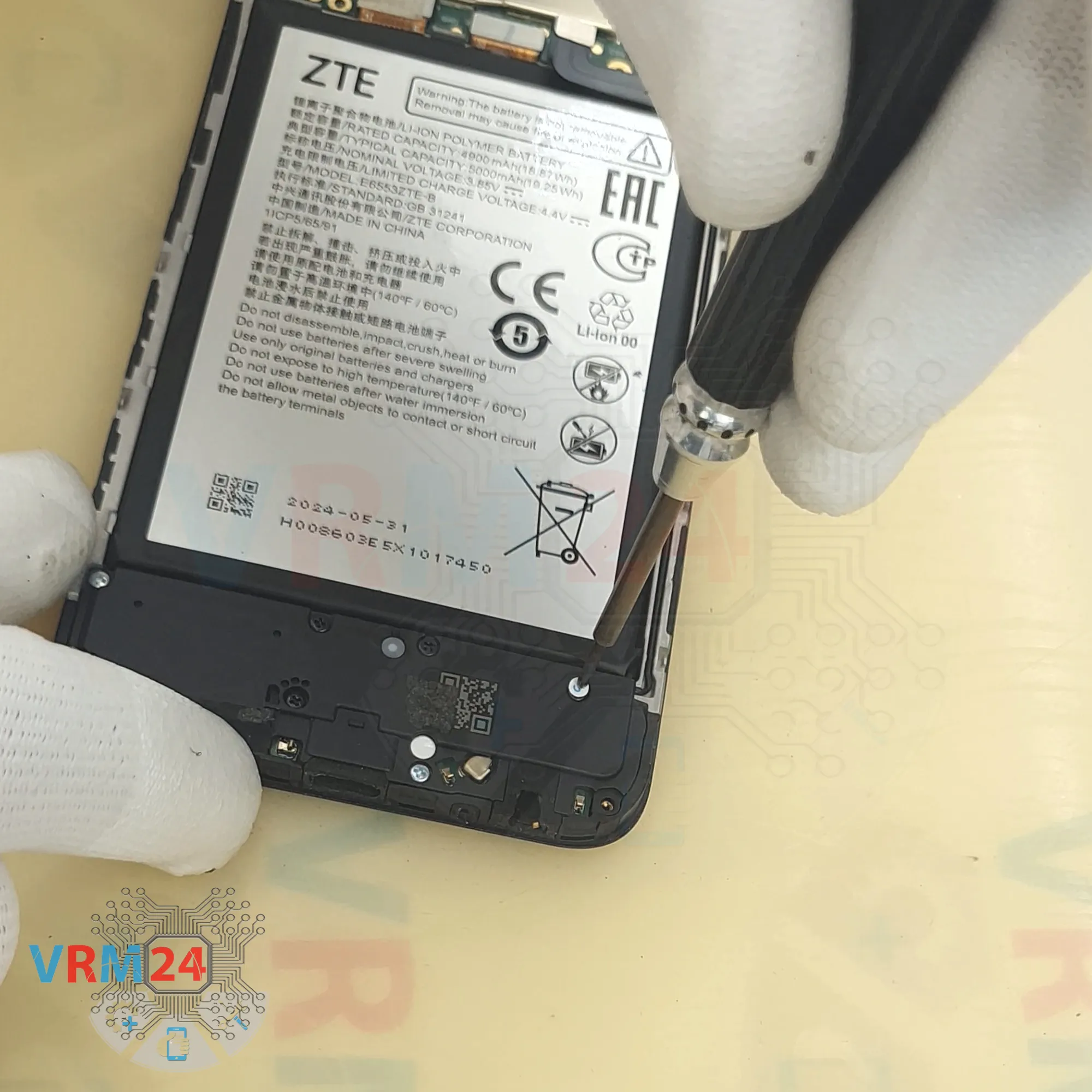
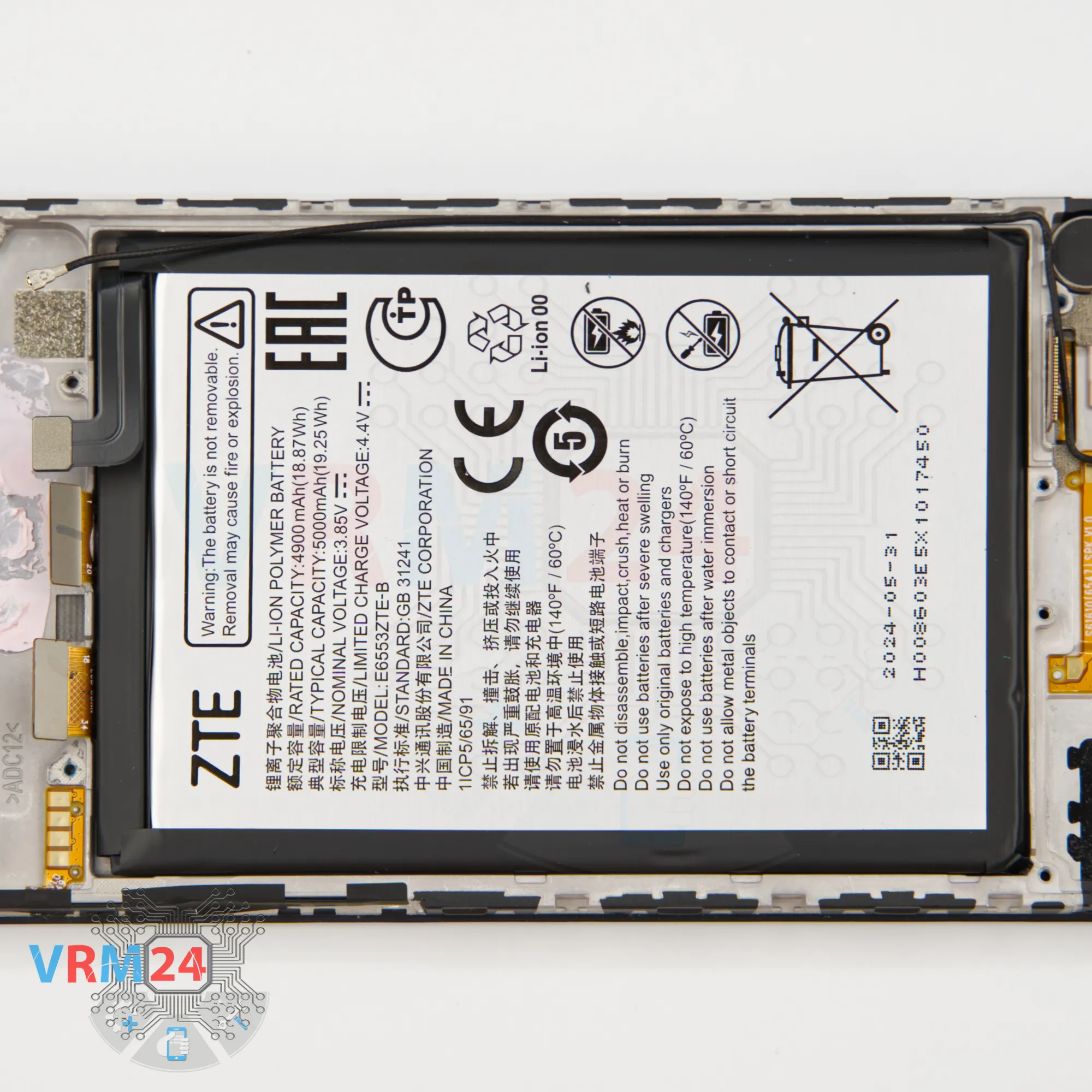
ℹ️️ The ZTE Blade V50 Design ZTE 8050 model has a battery E6553ZTE-B with a capacity of 5000 mAh (also known as a rechargeable battery).

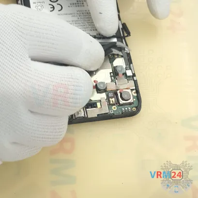

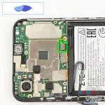
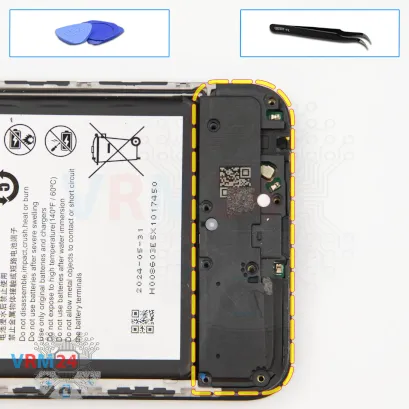
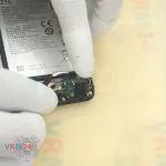
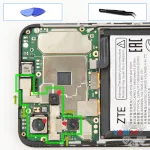
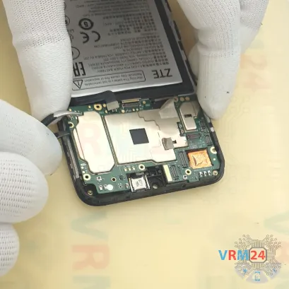
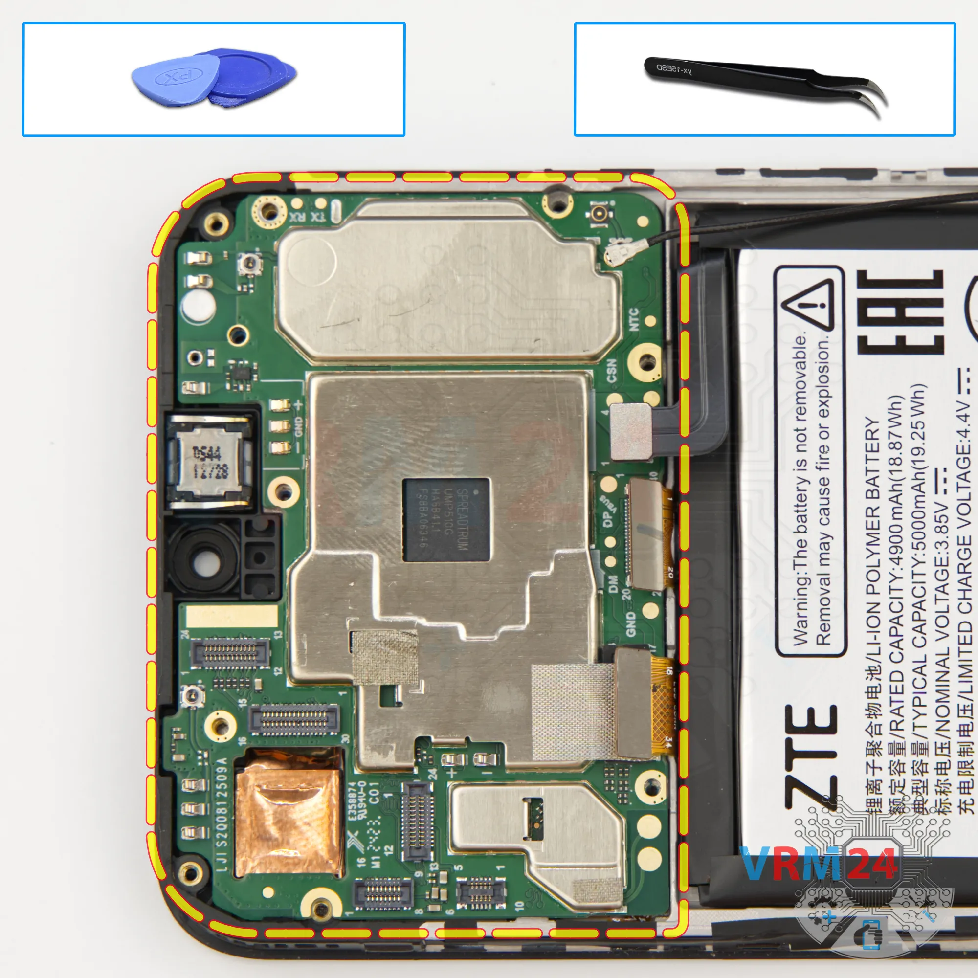
Step 11. Remove the fingerprint sensor
And we can also disconnect the fingerprint sensor flex.
Unplug the connector and gently peel off the flex cable, which is attached to the motherboard shield.
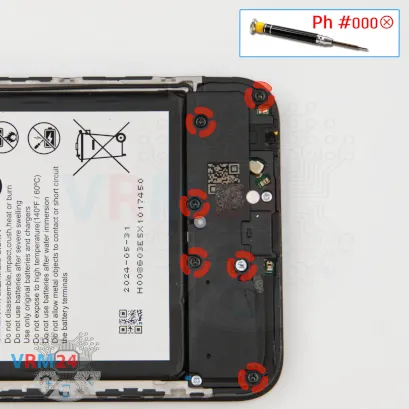

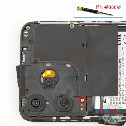
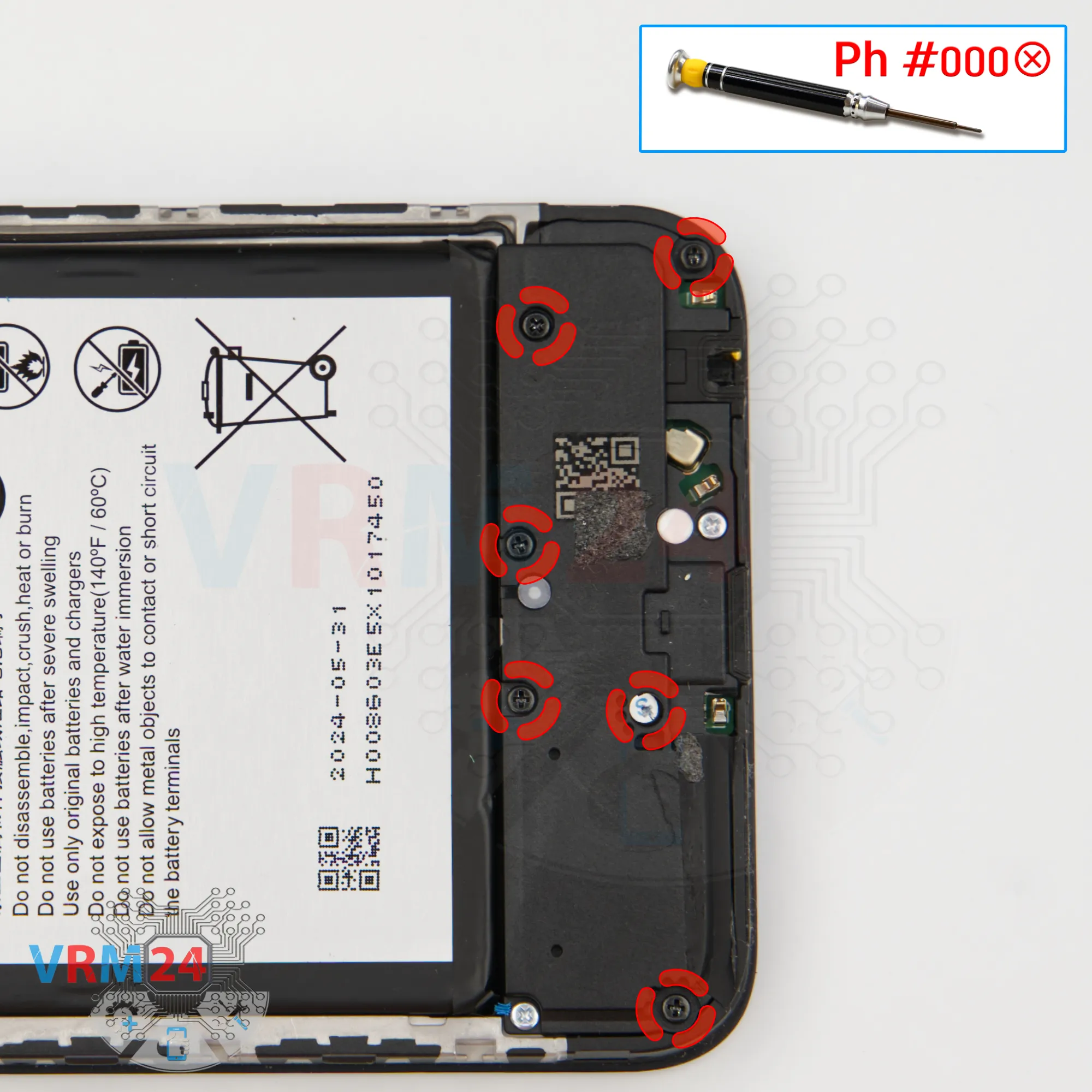
Step 12. Unscrew the screws
Now we can move down to the lower section.
Here too, we need to unscrew the six black screws.
These may also differ from the previous ones, so keep them organized separately.
We use the same 1.5 mm Phillips or #000 screwdriver.

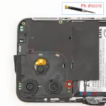
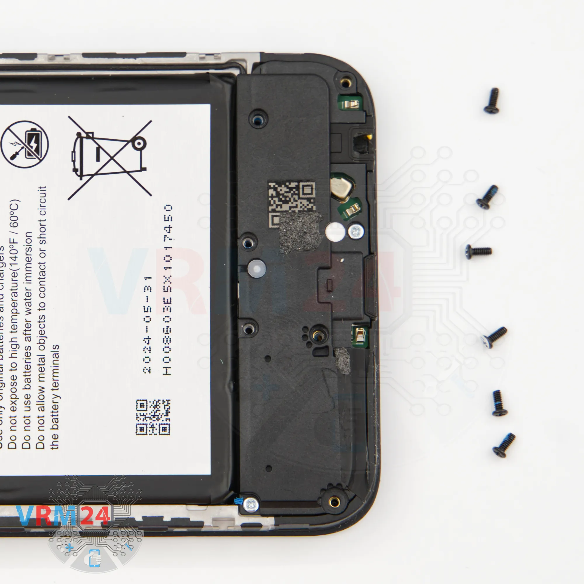
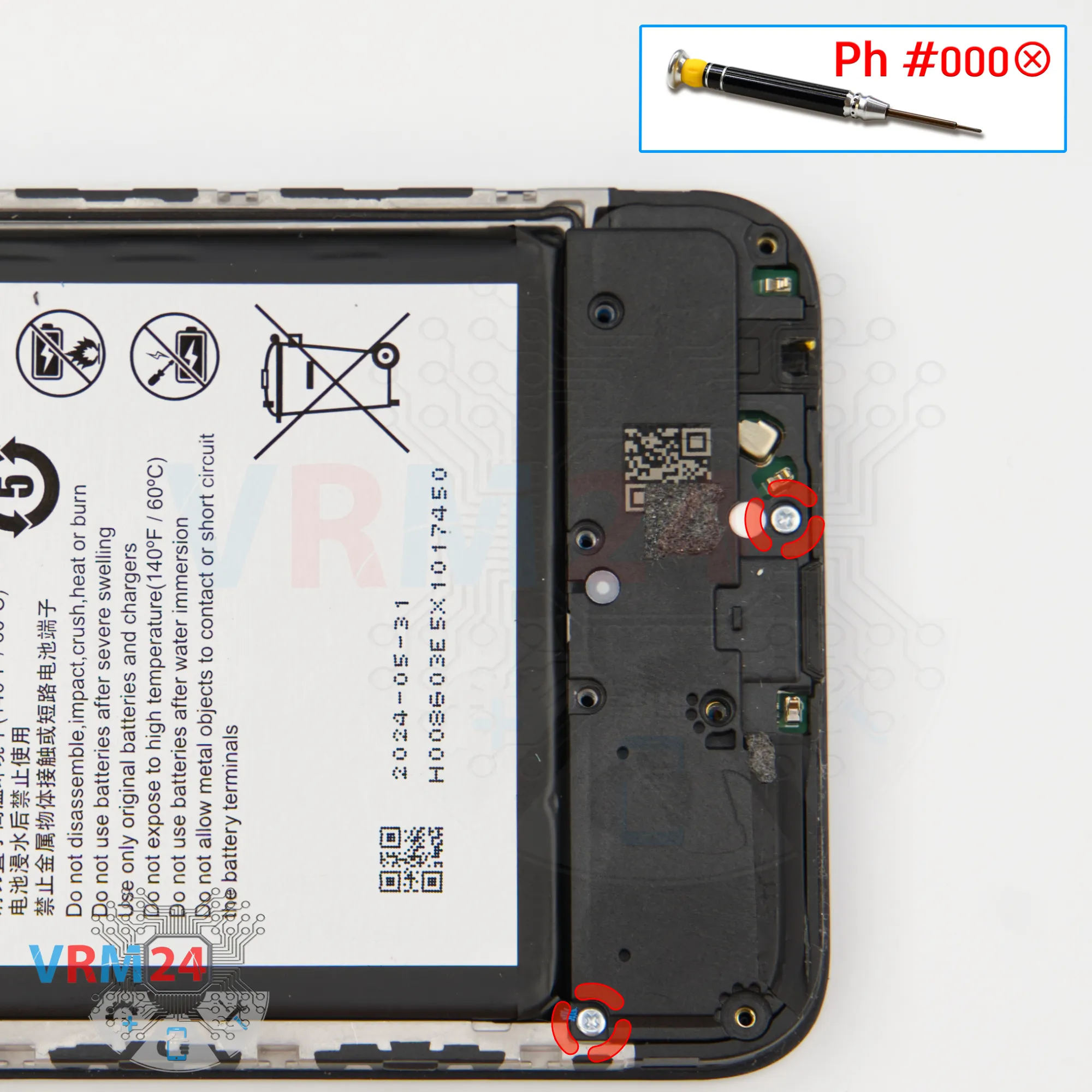
Step 13. Unscrew the screws
Using a screwdriver Phillips 1.5 mm (PH #000), unscrew the two silver screws.

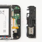
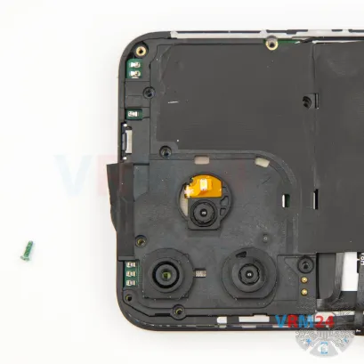
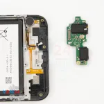
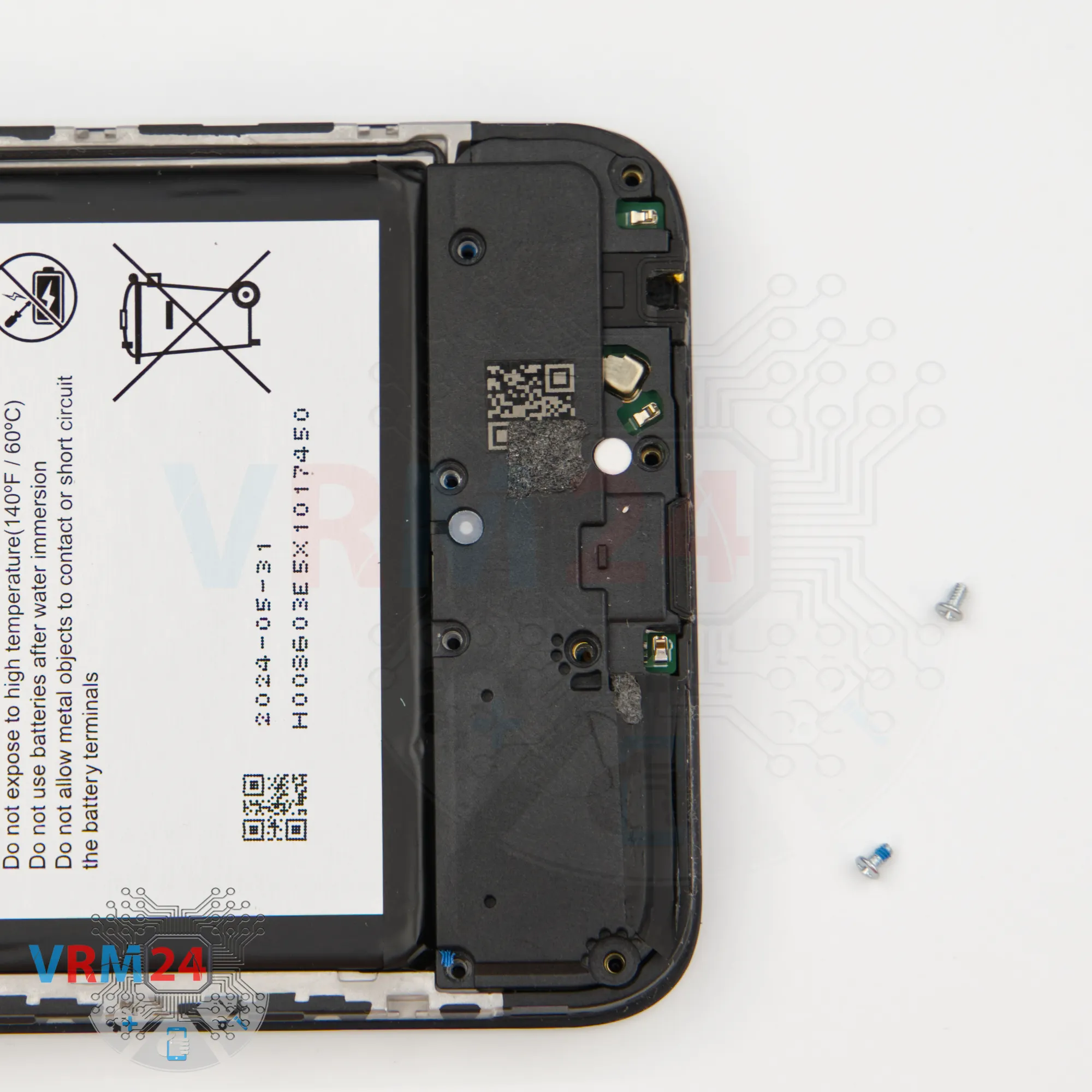
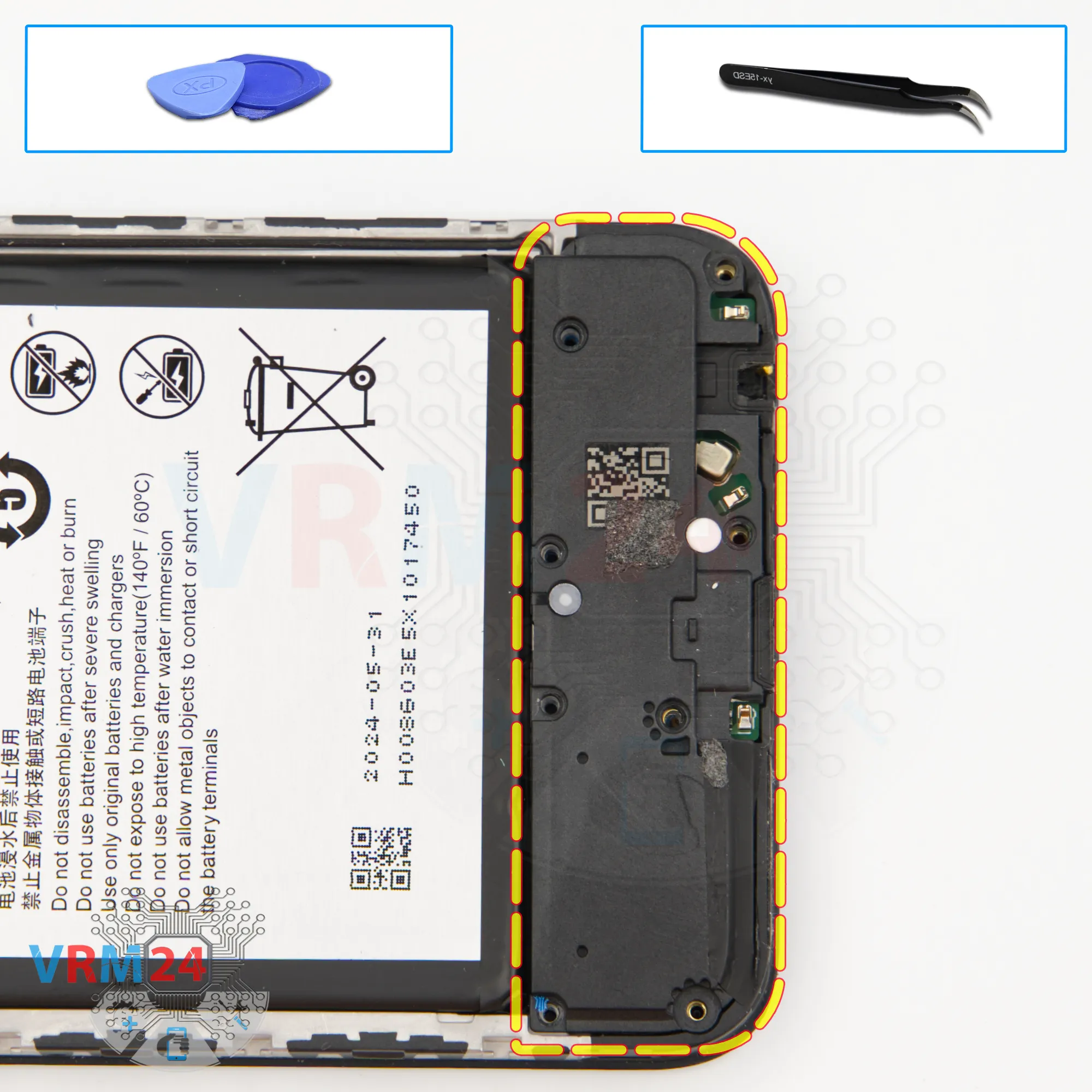
Step 14. Remove the loudspeaker
After unscrewing, we can remove the cover—this one likely includes the loudspeaker.
Find a spot to pry under, lift it up, and detach the cover. Indeed, when we flip it over, we see the speaker mounted inside.


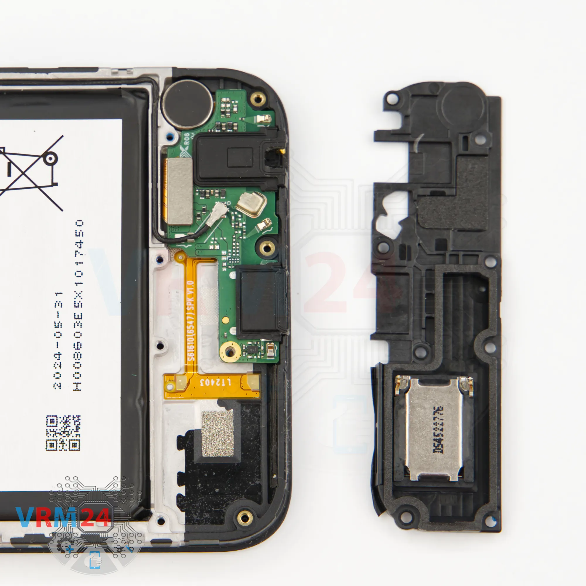
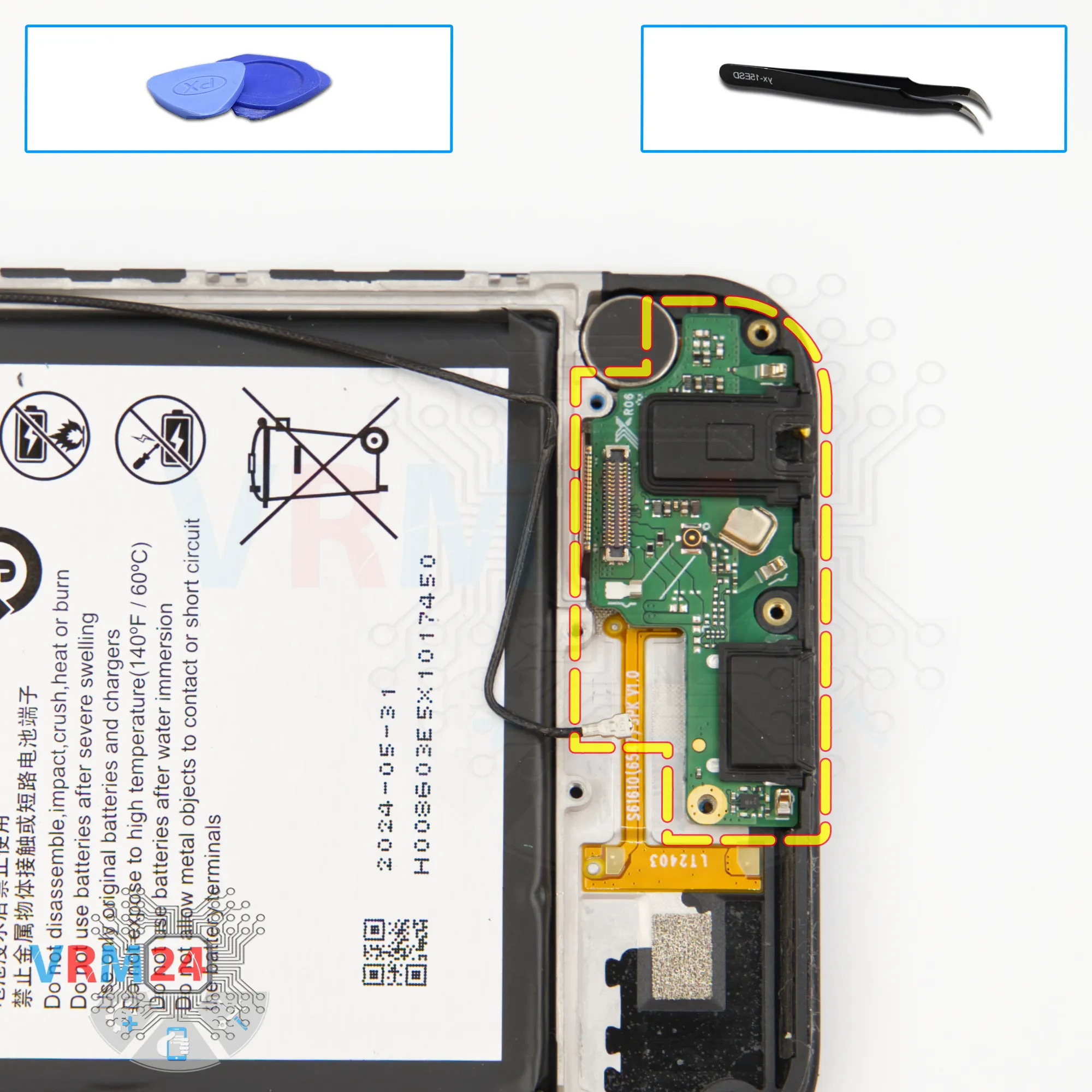
Step 15. Disconnect the connectors
Next, disconnect the coaxial cable connector, free the cable, and then disconnect the inter-board flex connector.
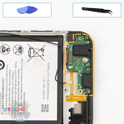


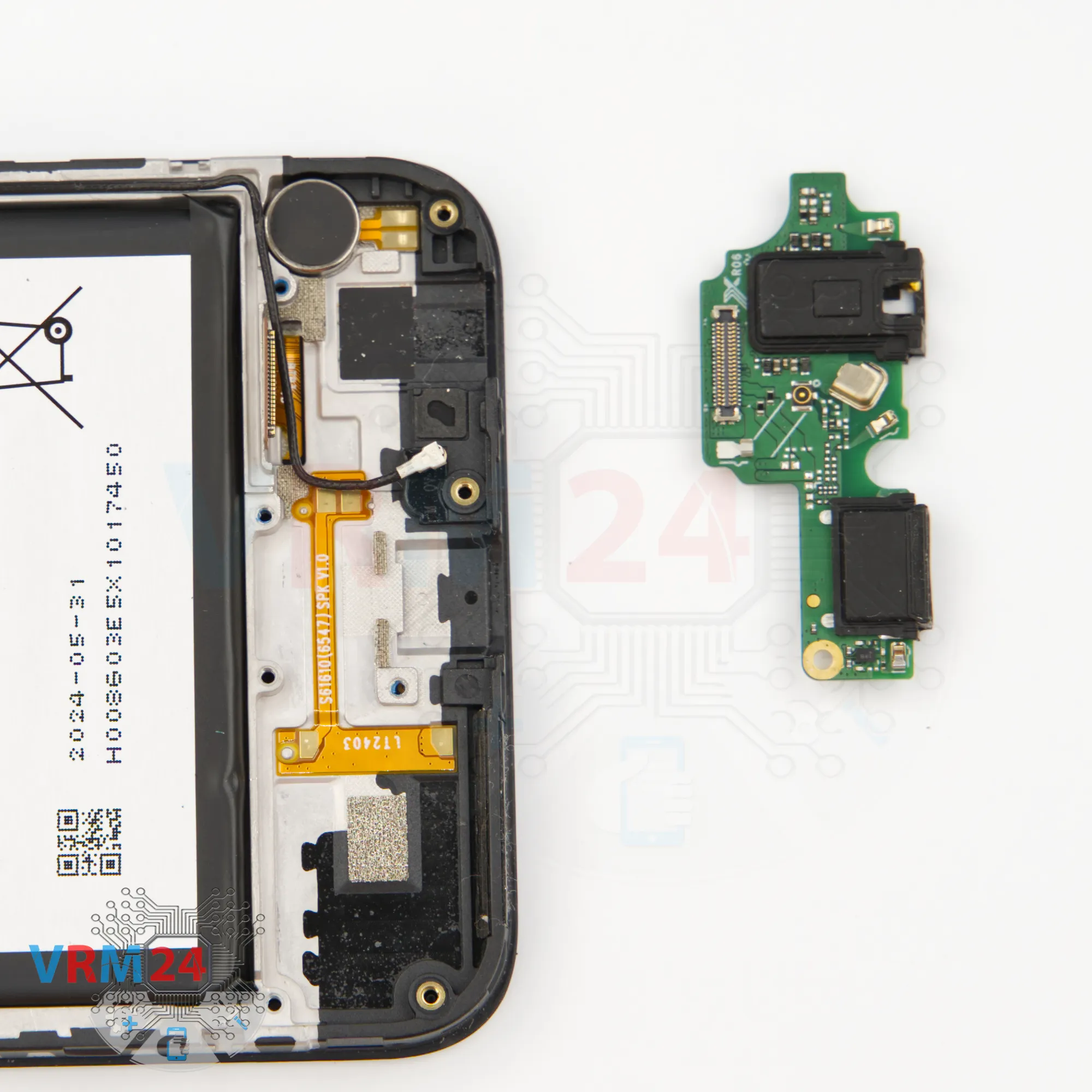
Step 16. Remove the sub-board
Now we can remove the sub-board.
As always, carefully pry it up, lift it, and take it out.
On the sub-board, we have the charging port, microphone, and headphone jack.

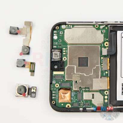
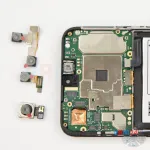
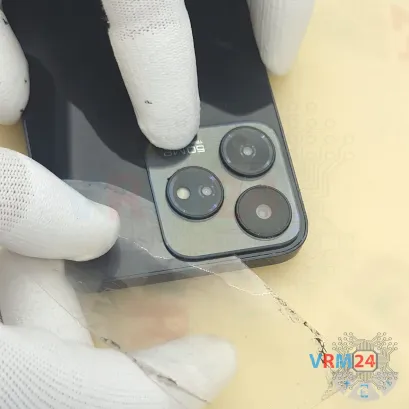
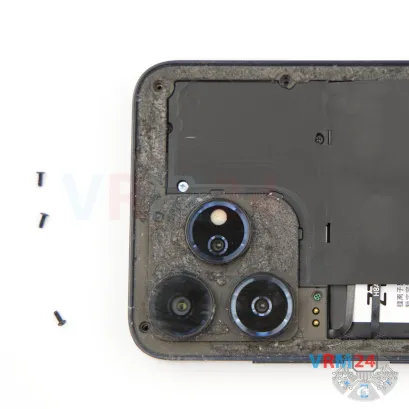
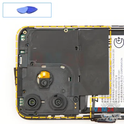
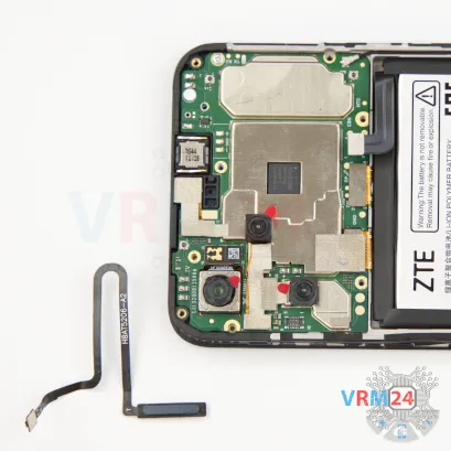
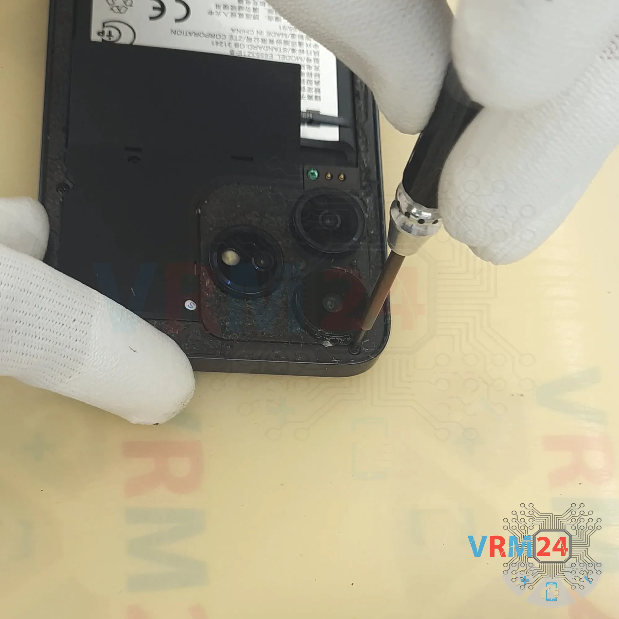
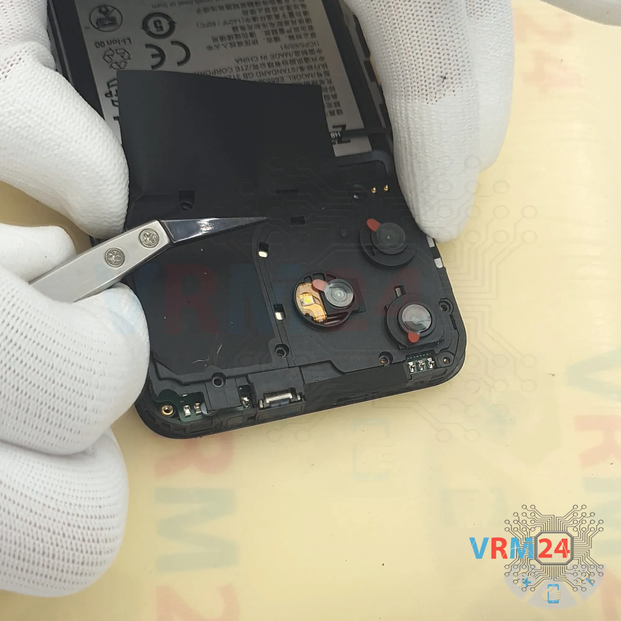
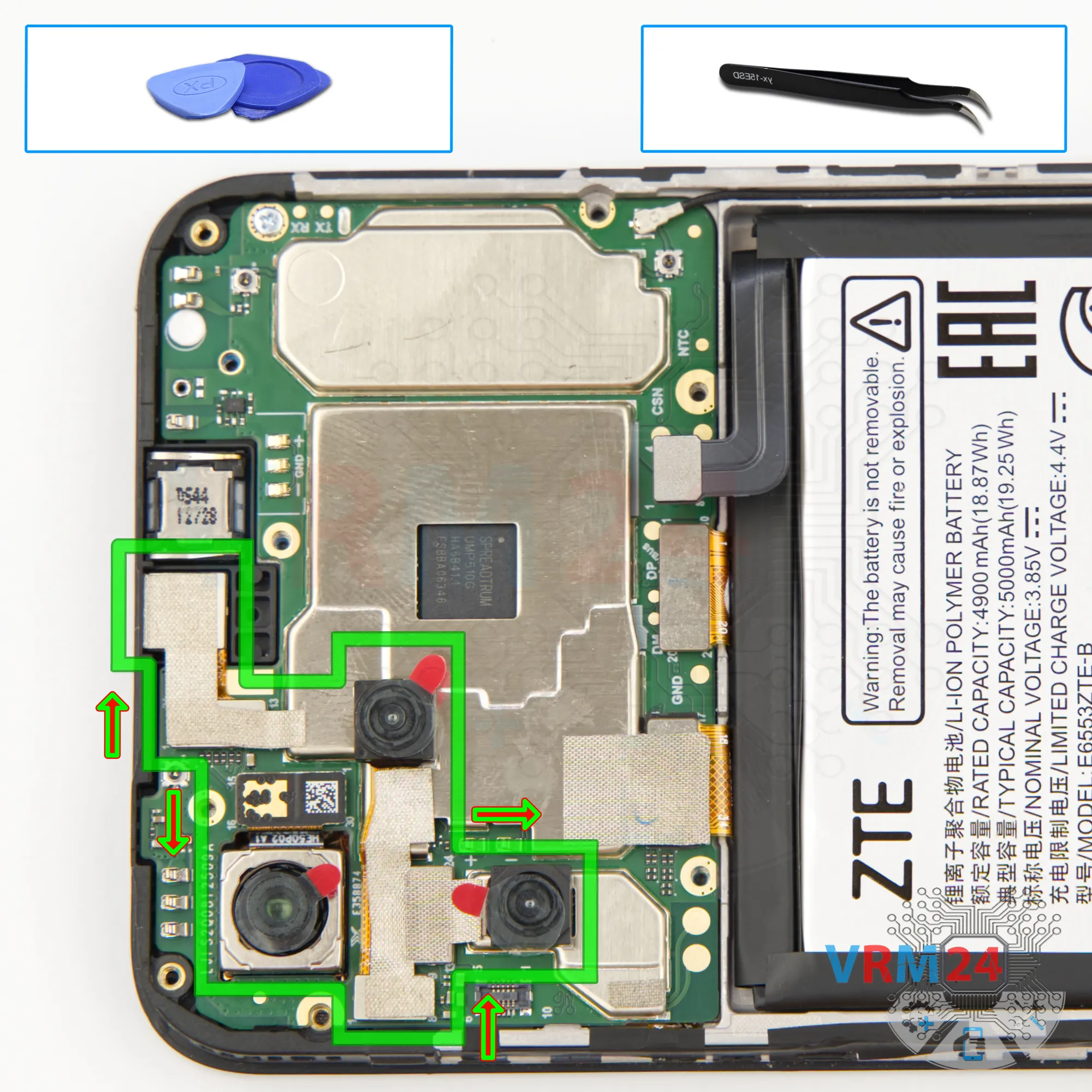
Step 17. Remove the cameras
Now we can remove the cameras.
As we can see, they are bonded together with a heat-dissipating foil. Handle them with care.
The main rear camera is also slightly glued to the display frame.
So, carefully detach the rear cameras—remember, they’re connected by that thermal foil. Don’t pull hard on the flex cables to avoid tearing them. Set the cameras aside.
We can also remove the front camera. Again, peel back the thermal foil—it will be useful during reassembly.


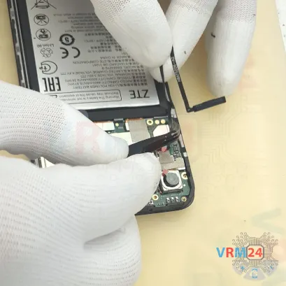
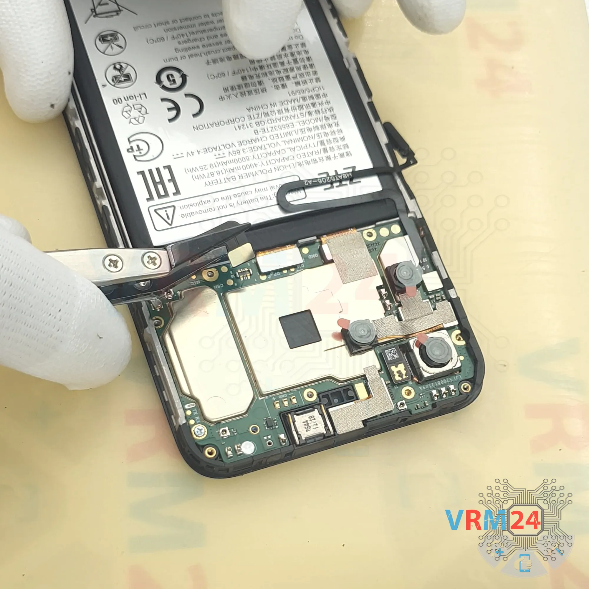
Step 18. Disconnect the connectors
And we disconnect the coaxial cable connector, then the inter-board flex, then the display flex connector.
Peel back the thermal foil—it’ll also be reused during reassembly.
Step 19. Unscrew one screw
After that, check for another screw securing the motherboard. For this, we use the same 1.5 mm Phillips or #000 screwdriver.


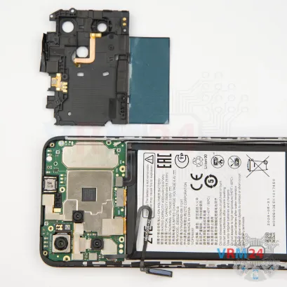
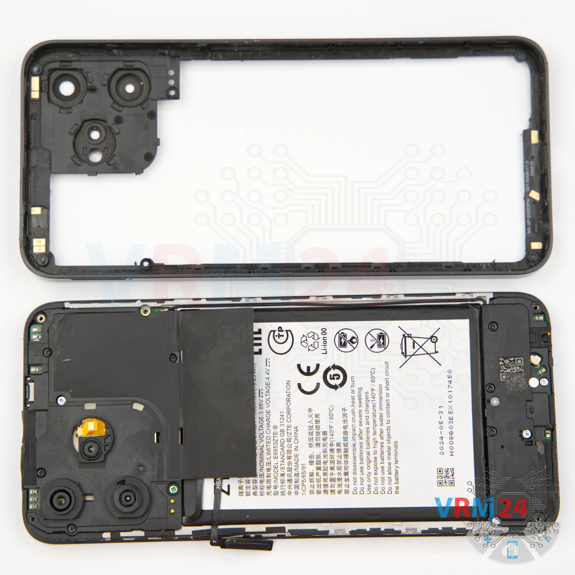
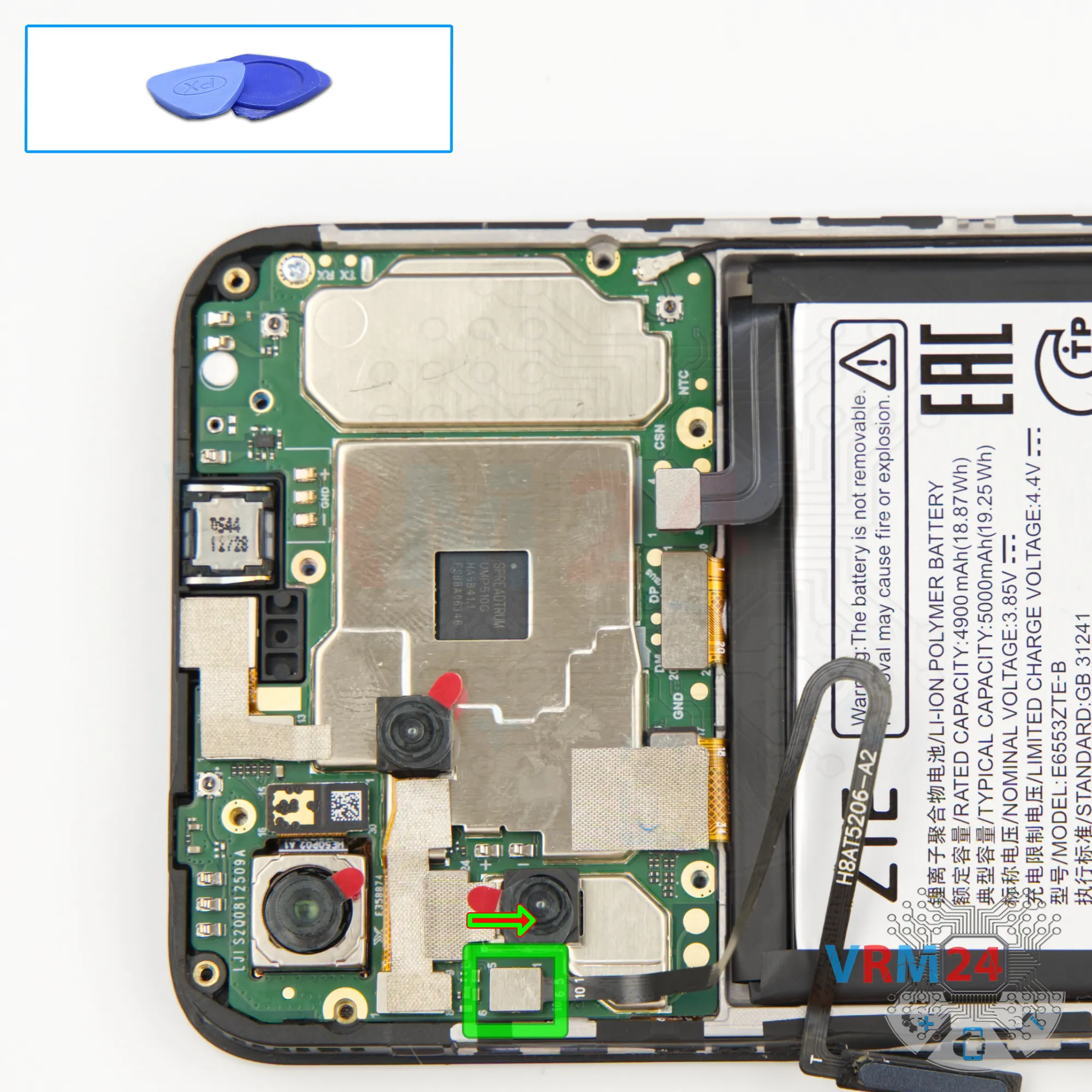
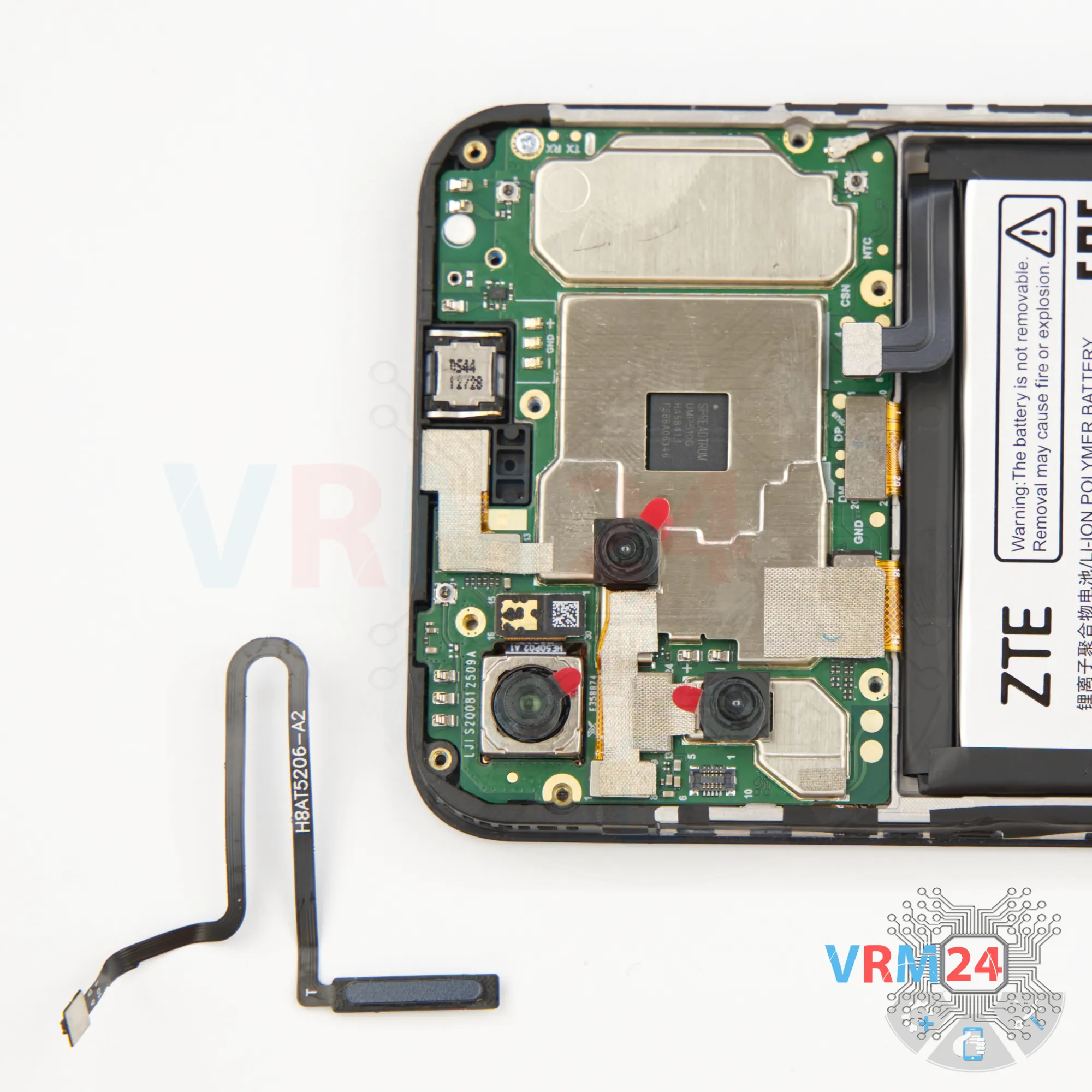
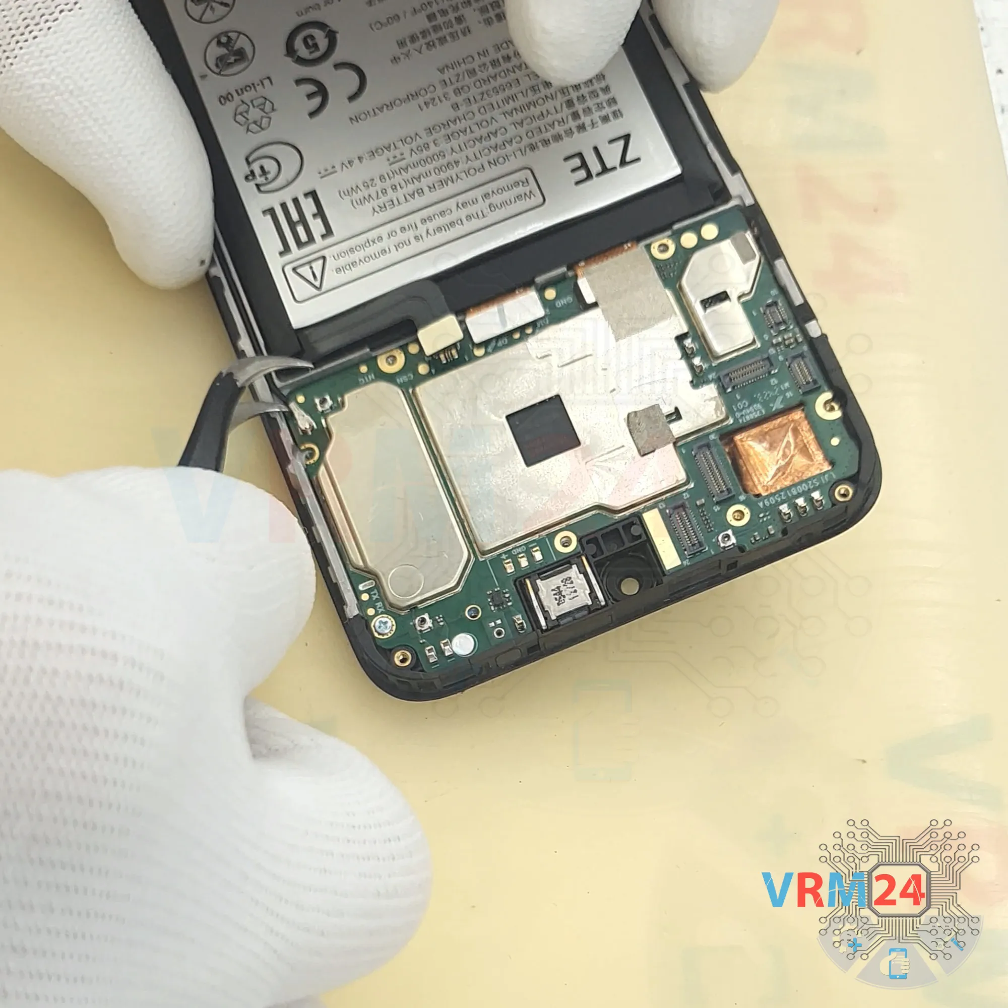
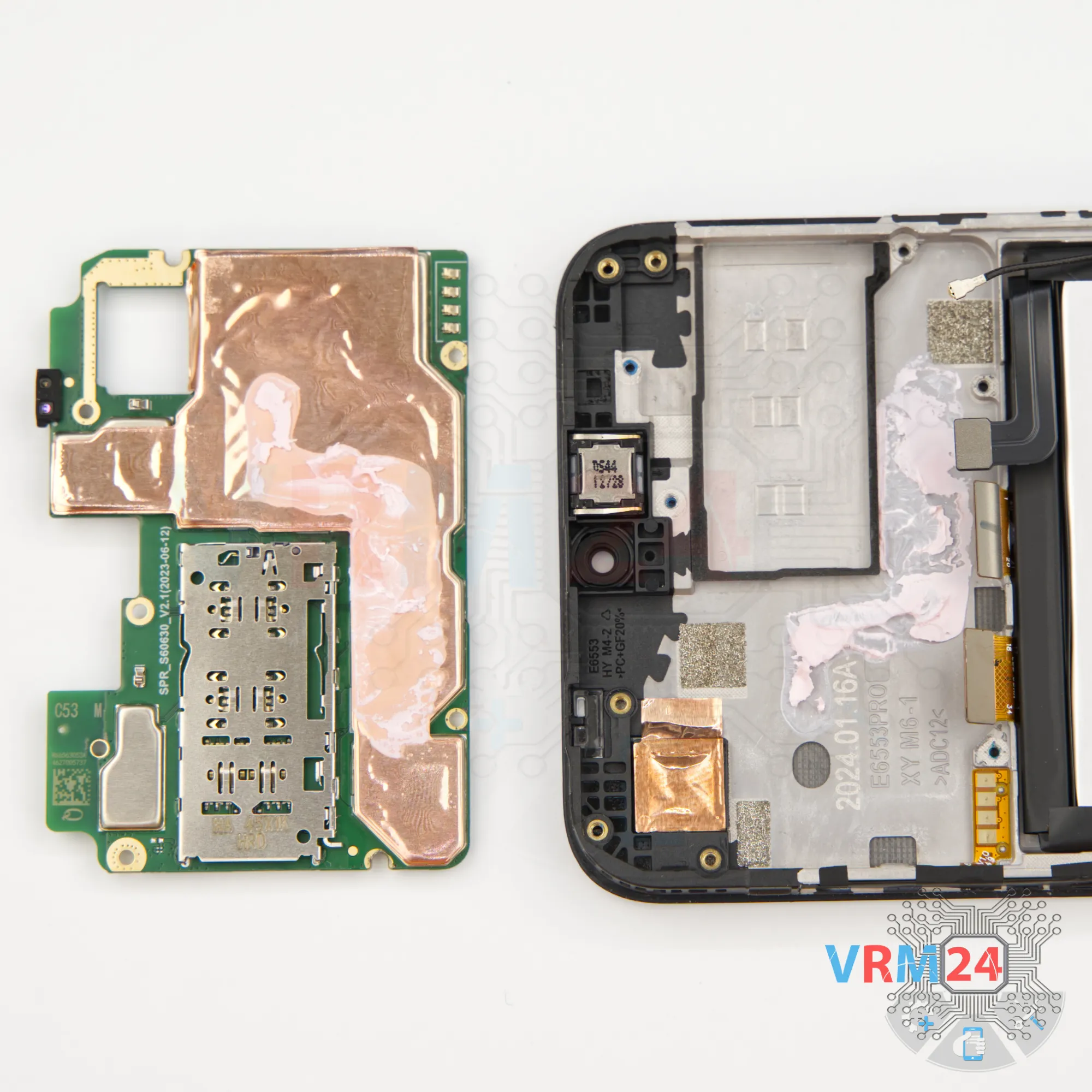
Step 20. Remove the motherboard
Now nothing’s in the way. Carefully pry up the board at the right spot and lift it out.
⚠️️ Do not bend the circuit board when removing it or push tools under it. Unbeknownst to yourself, you can damage components or cables from the inside.
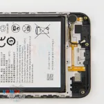
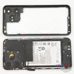
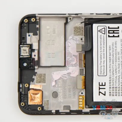
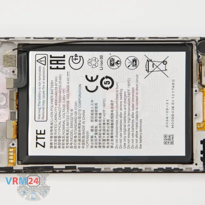
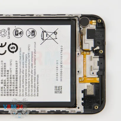
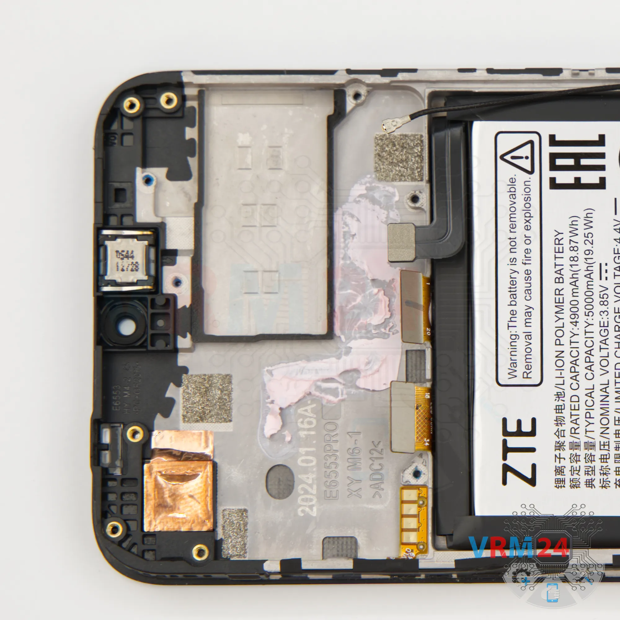
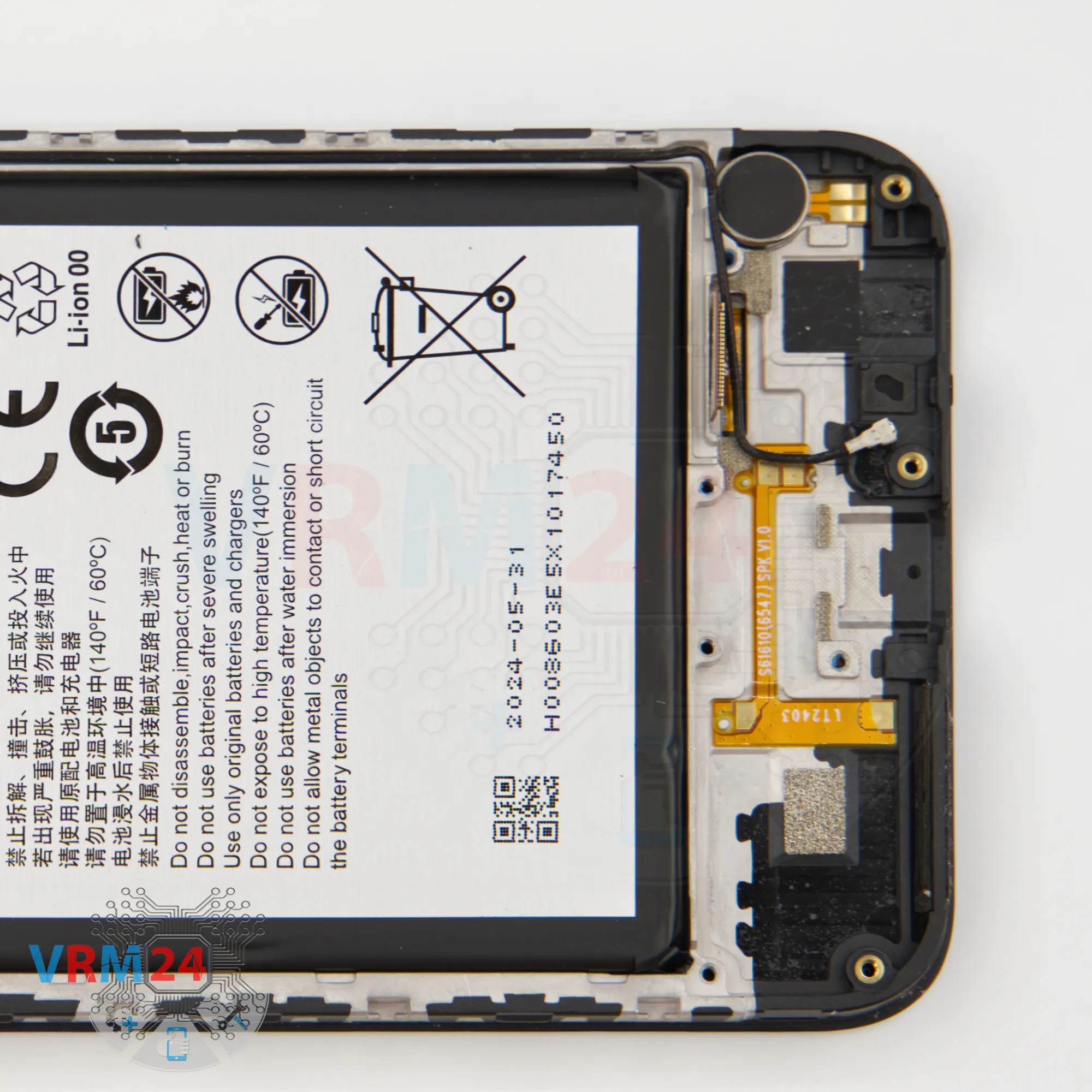
Step 21. In the display frame remained
ℹ️️ In the display frame remained: the earpiece speaker, battery, and vibration motor.
Detailed disassembly instructions of ZTE Blade V50 Design in the video, made by our mobile repair & service center:
If you have a question, ask us, and we will try to answer in as much detail as possible. If this article was helpful for you, please rate it.

Disassembling\Repair has medium complexity and takes about minutes in time.
Our manual is suitable for all models ZTE Blade V50 Design — ZTE Blade V50 Design ZTE 8050 released for markets in different countries.
Back to the list