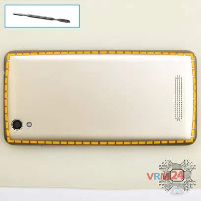
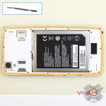
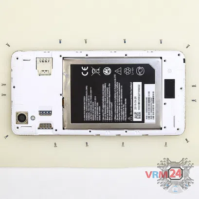
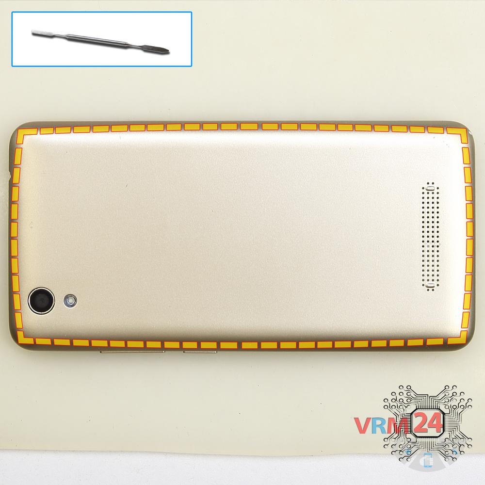
Using a spudger or a plastic pick, carefully, around the edge, detach the back cover clips, and remove it.
Do not insert the tool deeply or bend it. Otherwise, the housing may be tampered with or damaged.
To ask the question please sign in with one of your existing third party accounts.
To get notifications please sign in with one of your existing third party accounts.
Please sign in with one of your existing third party accounts.


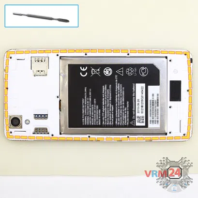
Using a spudger or a plastic pick, carefully, around the edge, detach the back cover clips, and remove it.
Do not insert the tool deeply or bend it. Otherwise, the housing may be tampered with or damaged.
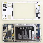
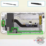
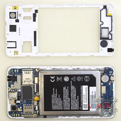
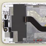
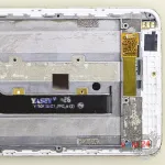
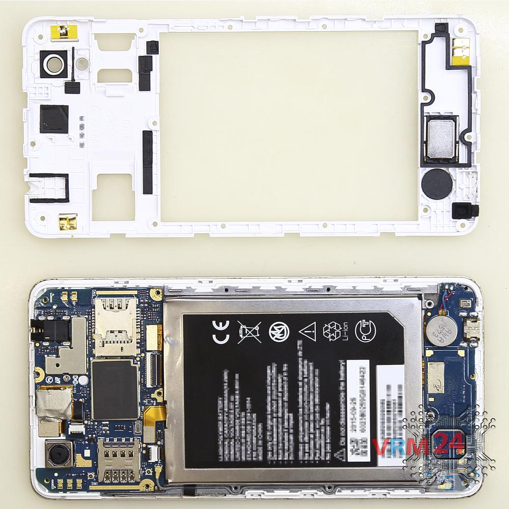
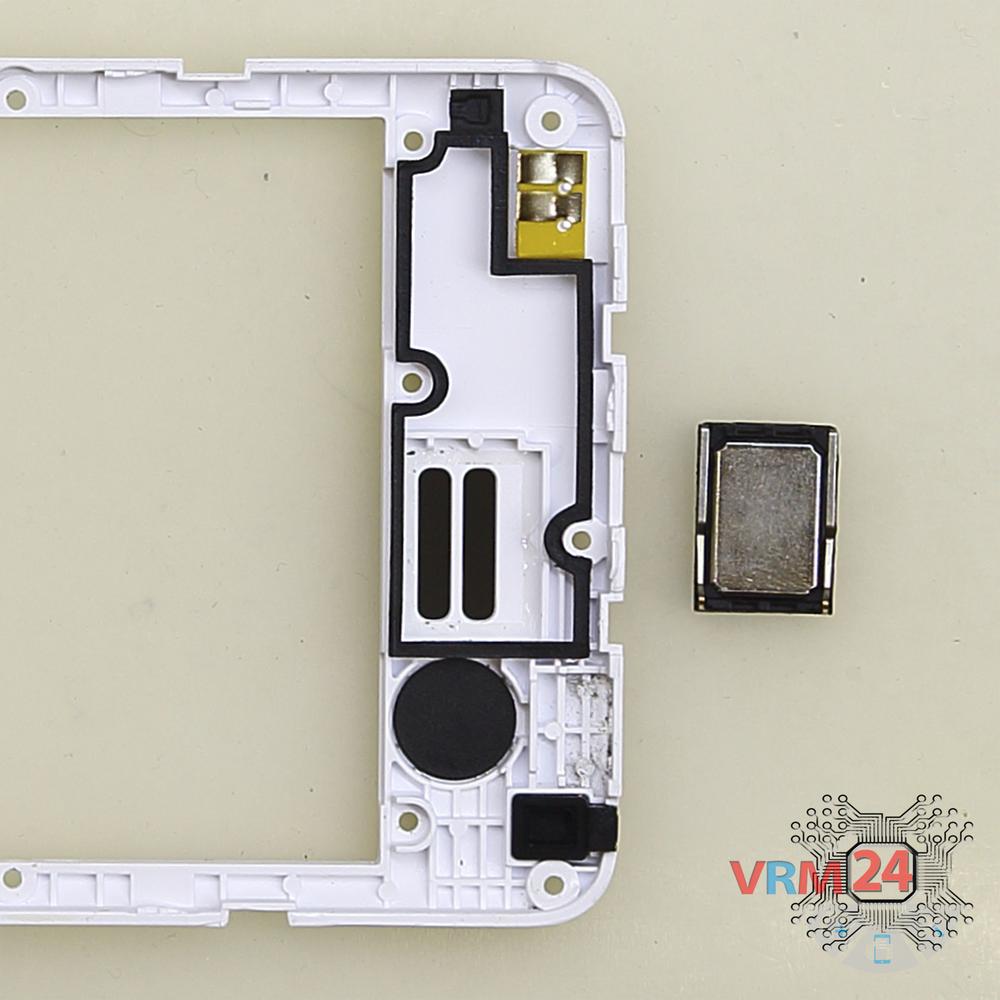
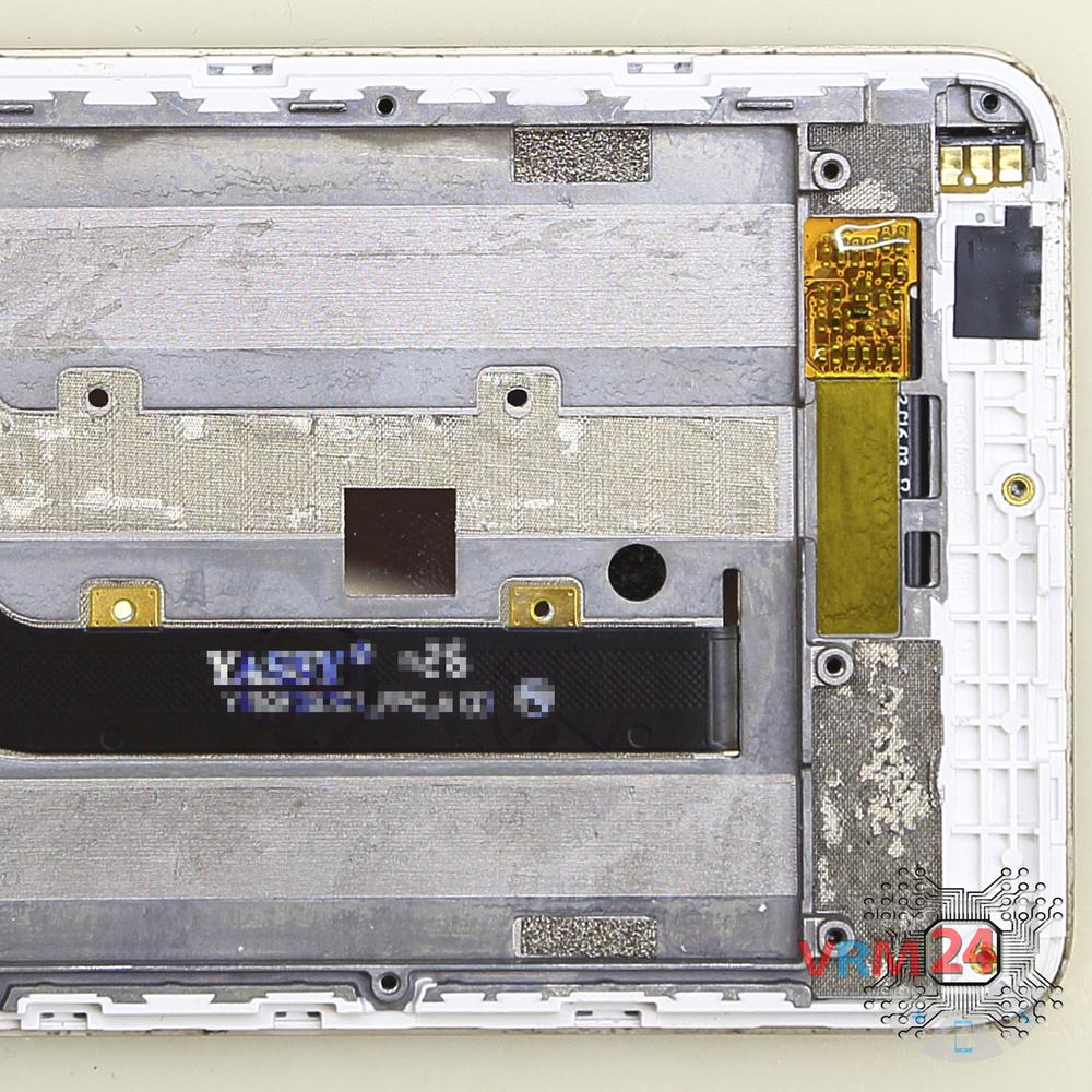
Pry over the edges. Move an opening tool along the edge detach the clips and remove the middle cover with a loudspeaker and antenna pads and tracks. The middle cover protects the printed circuit board (PCB).
Try to lift the cover by the edges and don't push anything too far inside, so as not to accidentally break or short-circuit anything on the circuit board.

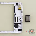
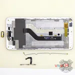
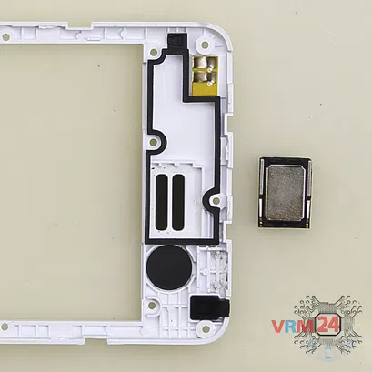
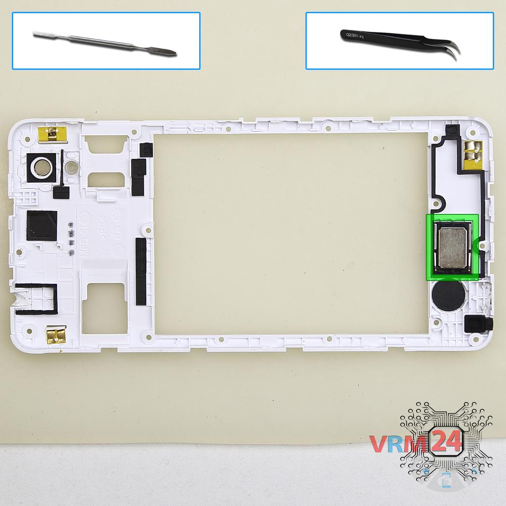
Pry at the bottom and remove the loudspeaker.
⚠️️ Be careful! The loudspeaker is glued a bit with adhesive.
⚠️️ If we pry the speaker in the middle we may break the loudspeaker in half.
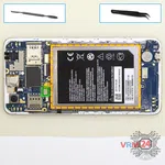


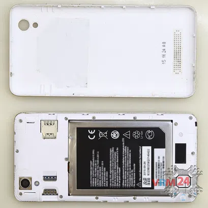
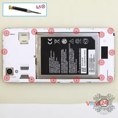
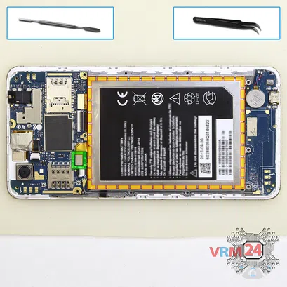
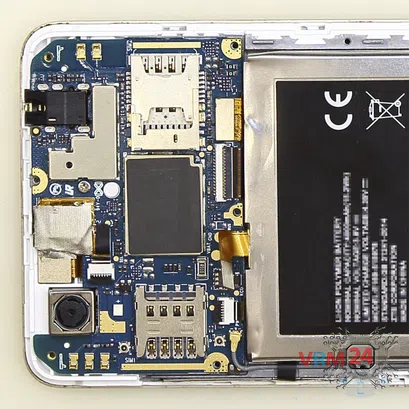
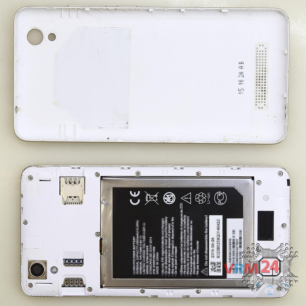
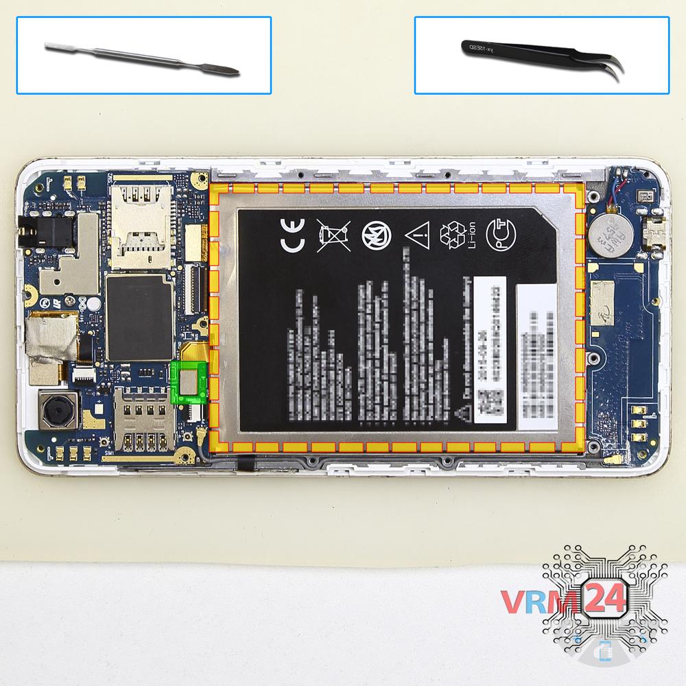
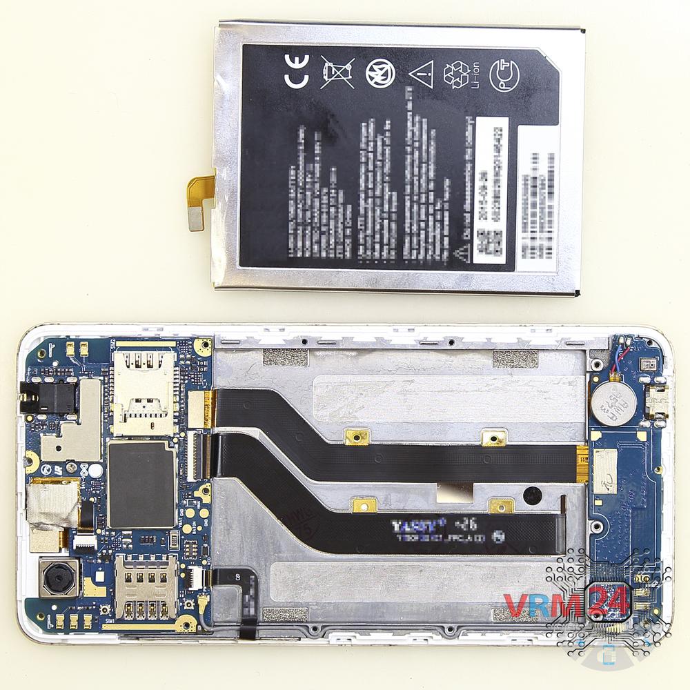
Disconnect the battery connector as soon as possible. It is better to use a non-metal or plastic tool to avoid any damage.
ℹ️️ The ZTE Blade X3 T620 model has a battery E169-515978 with 4000 mAh capacity (aka rechargeable battery).
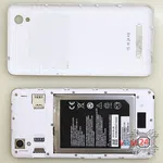
With extreme care, remove the battery because it is glued from the inside by the manufacturer.

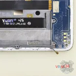

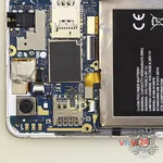
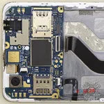
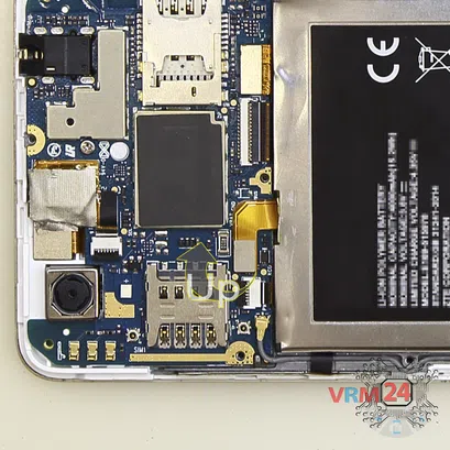
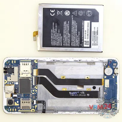
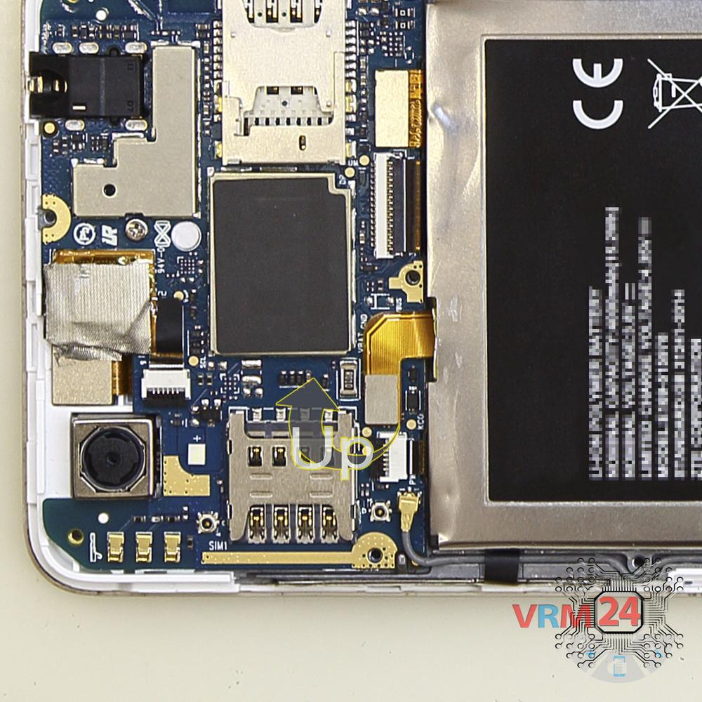
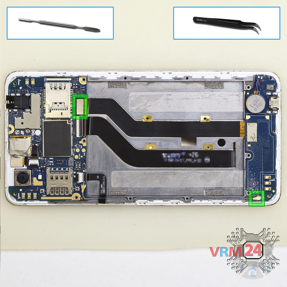
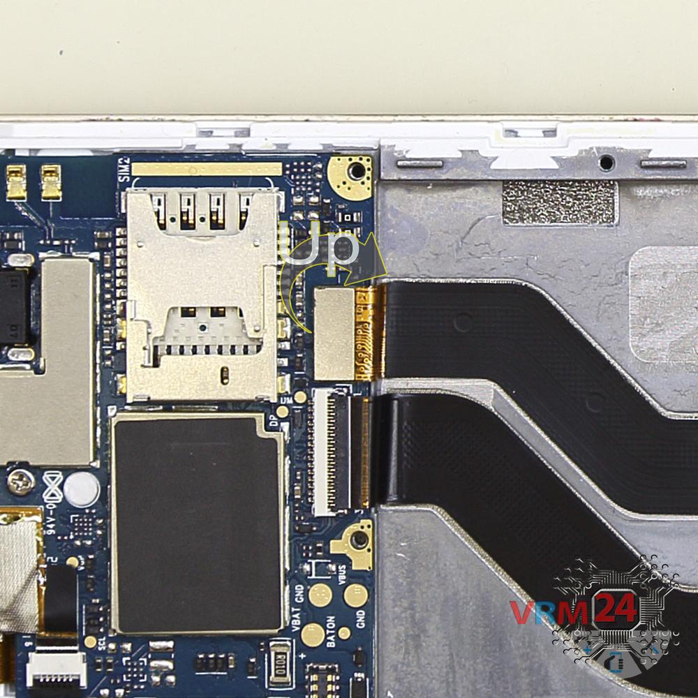
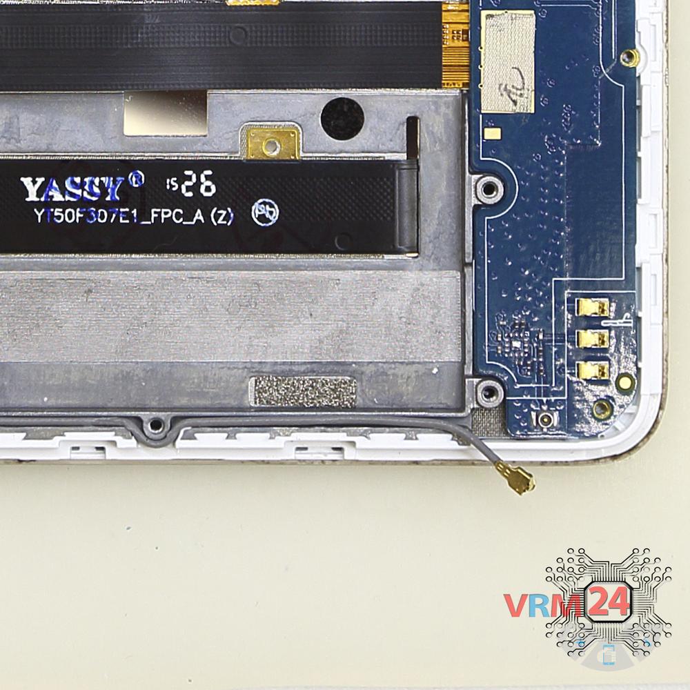
Disconnect the coaxial cable connector, connector of the inter-board cable on the motherboard.
⚠️️ Do not pull on the cable or pry it with a sharp tool, the connectors are pretty weak and break easily, or the cable falls out of the end (lug).
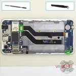
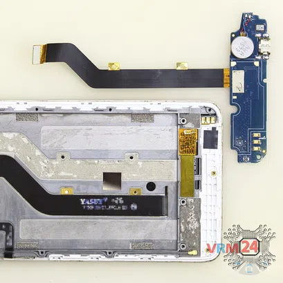
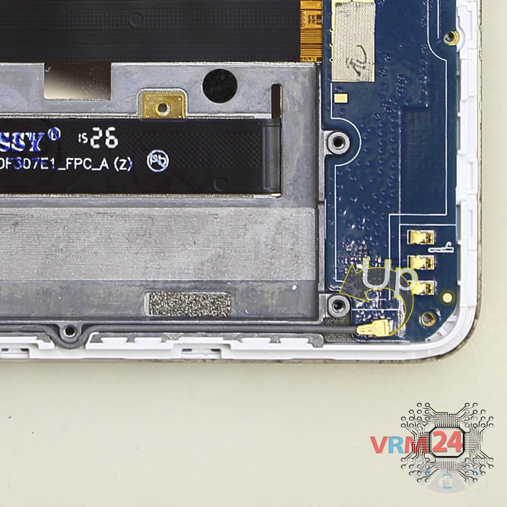
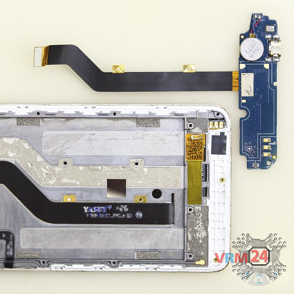
Unstick the flat inter-board cable and remove the sub-board. It may be glued to the frame or attached with attachments like latches or hooks, so be careful.
ℹ️️ The sub-board contains a charging port (Micro USB), microphone, vibration motor, inter-board cable, spring contacts for the speaker, and an antenna unit.
⚠️️ It is not necessary to insert the tool underneath when removing the sub-board. Internal components could be damaged.

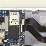
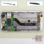
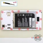
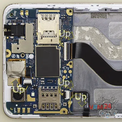
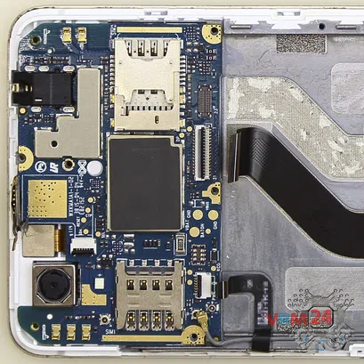
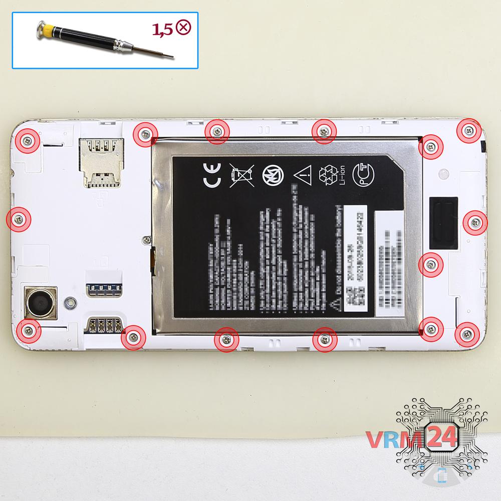
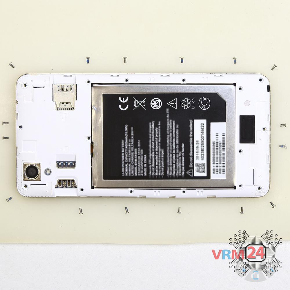
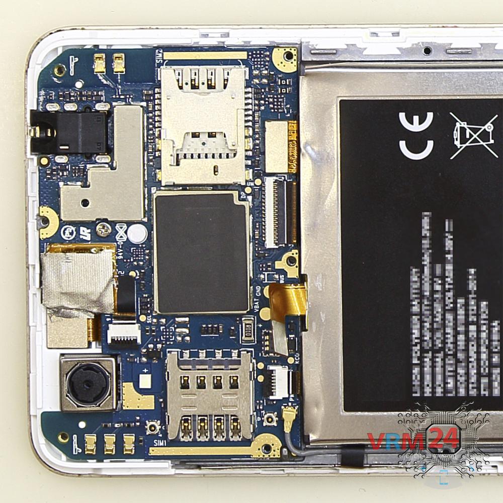
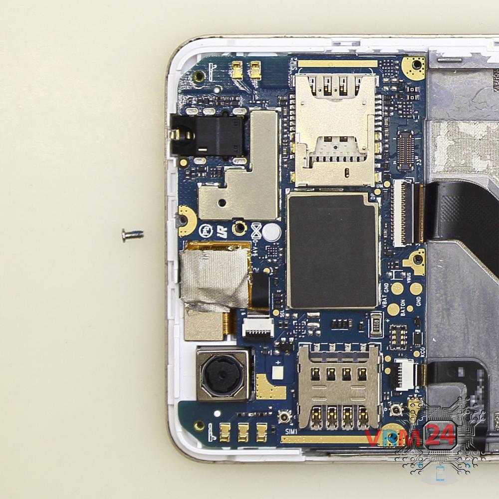
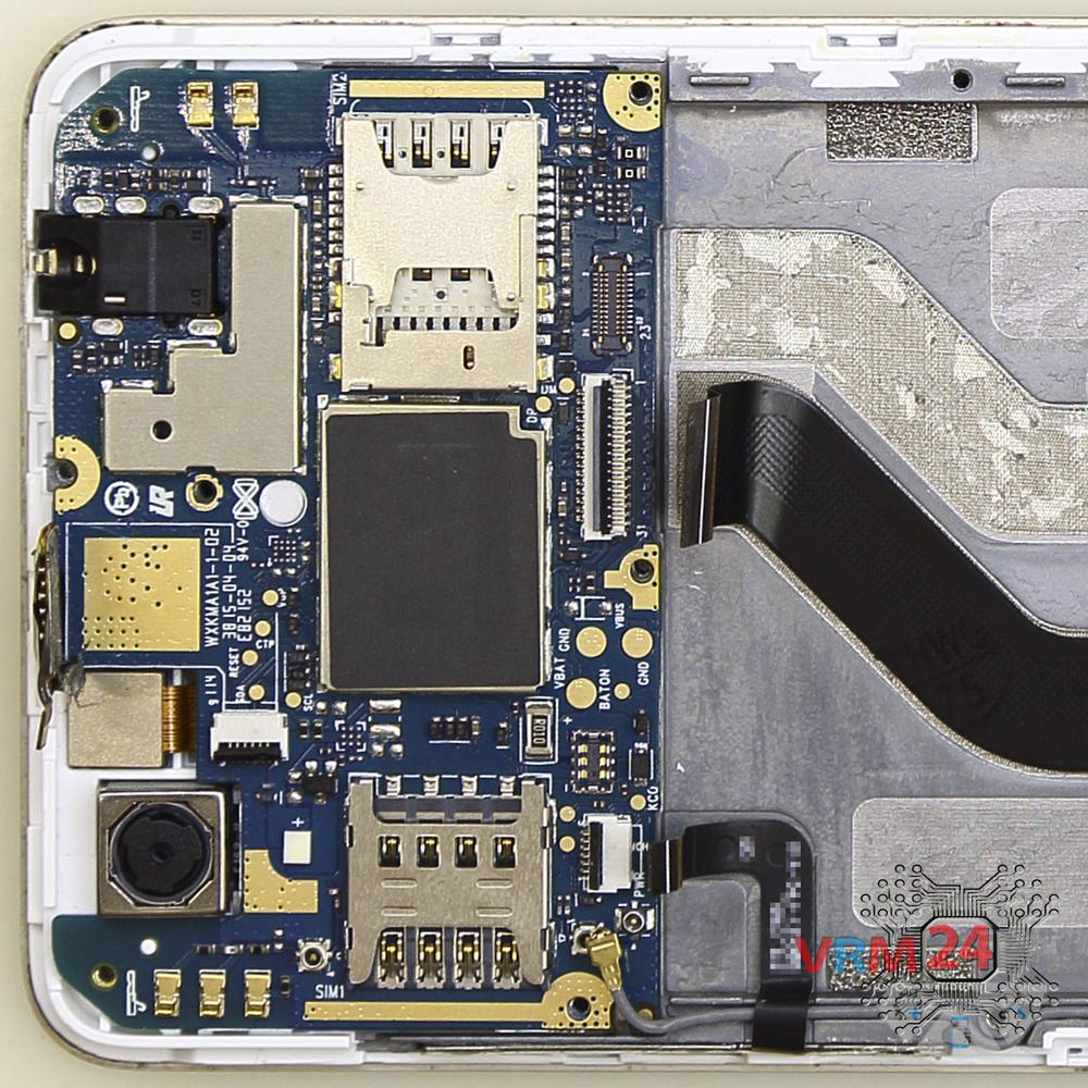
Using a screwdriver (Phillips 1.5 mm PH #000), unscrew one screw securing the motherboard.

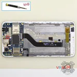
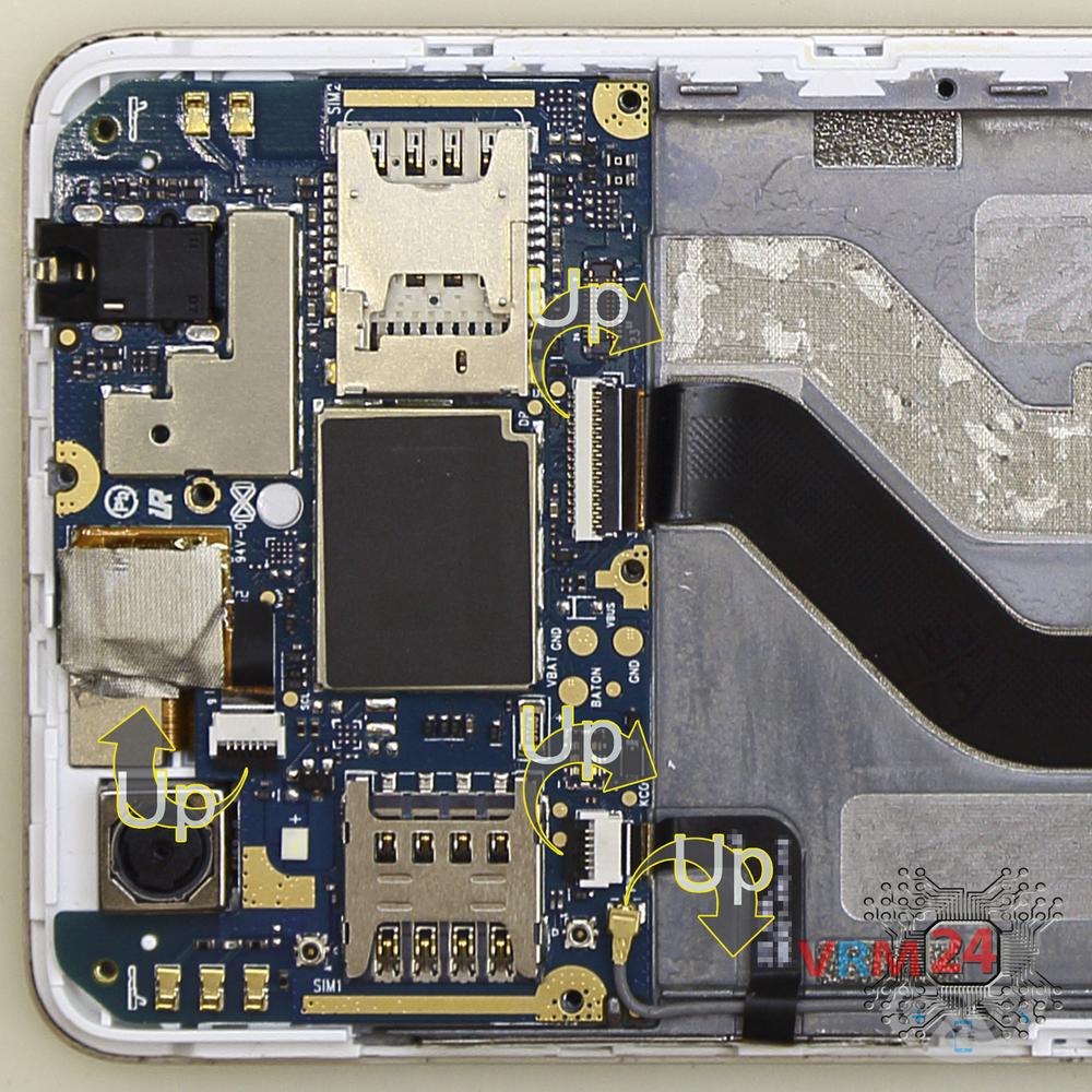
Pry up the connectors of the side buttons cable, display cable, touchscreen cable.
⚠️️ Be careful when removing the cables from the connectors, the cables are pretty thin, and it is easy enough to break them or damage the contact tracks inside.


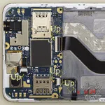
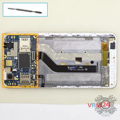
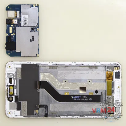
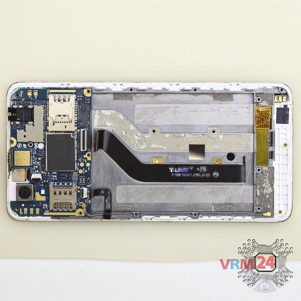
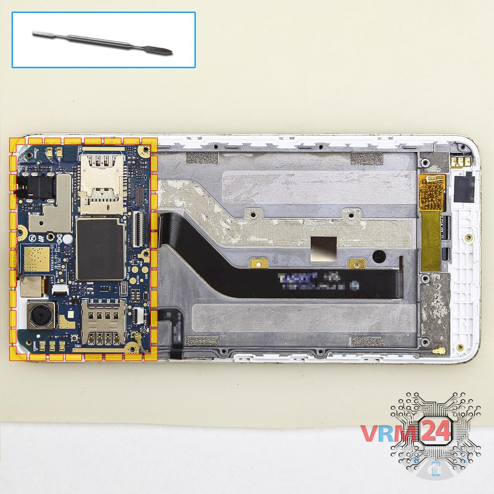
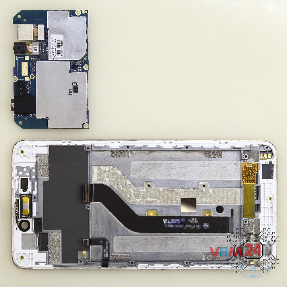
Carefully remove the printed circuit board. There is no need to use a lever or try to reach the circuit board by force. Make sure that nothing is getting in the way or holding the circuit board.
The motherboard, also, may be attached with attachments like latches or hooks, be careful.
⚠️️ Do not bend the circuit board when removing it or push tools under it. Unbeknownst to yourself, you can damage components or cables from the inside.
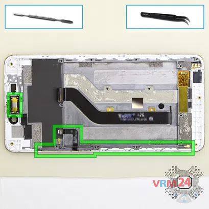
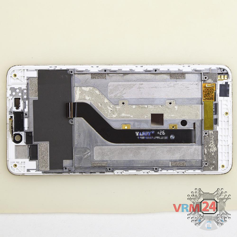
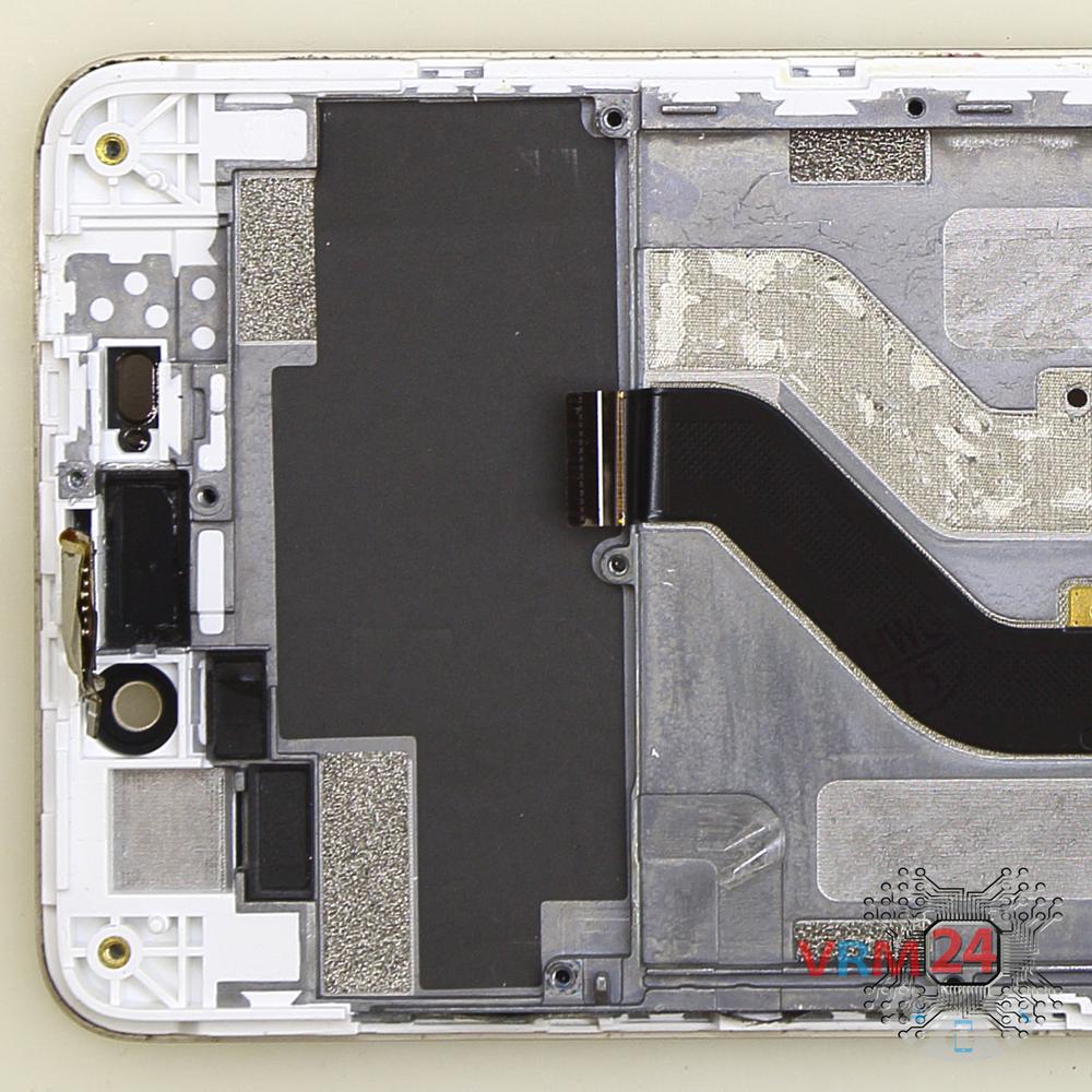
Pry at the bottom and remove the earpiece speaker.
⚠️️ Be careful! The earpiece speaker is glued a bit with adhesive.
⚠️️ If we pry the speaker in the middle we may break the earpiece speaker in half.
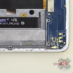
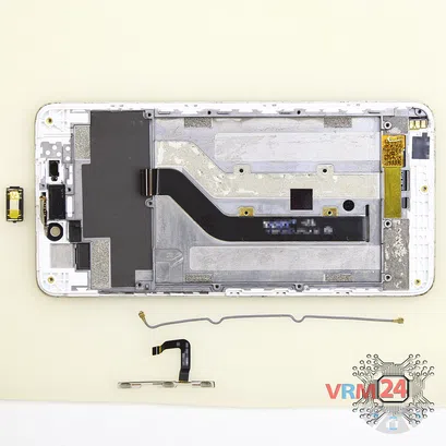
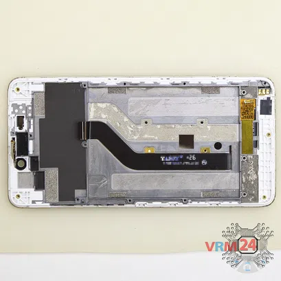
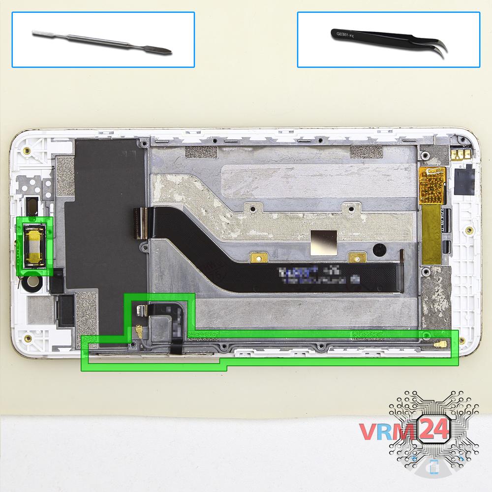
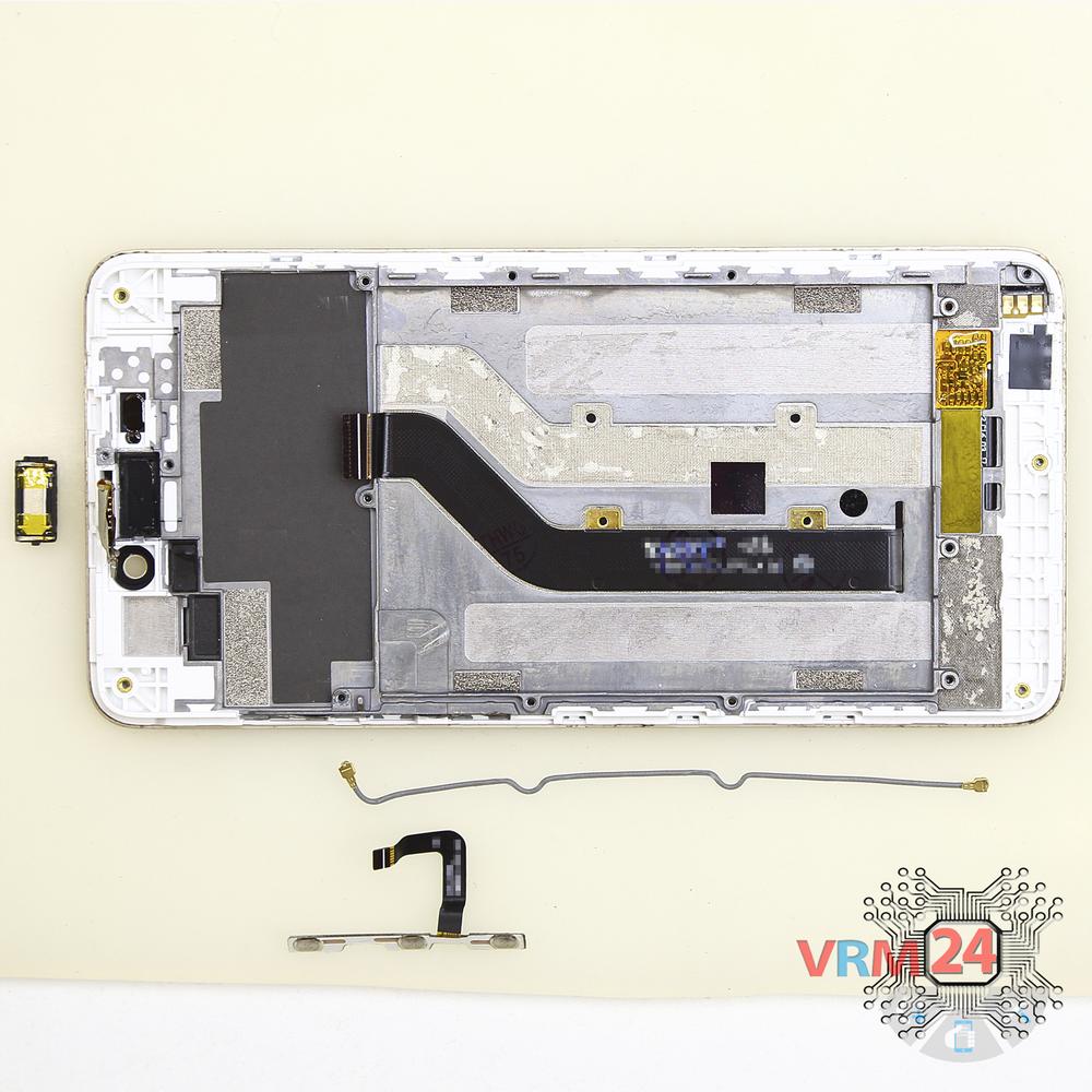
Carefully unstick the side buttons.
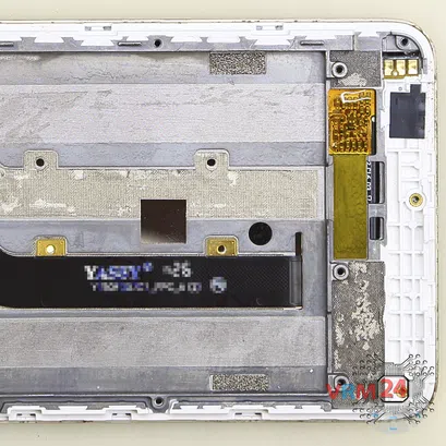
Also, we detach the coaxial cable.
If you have a question, ask us, and we will try to answer in as much detail as possible. If this article was helpful for you, please rate it.


