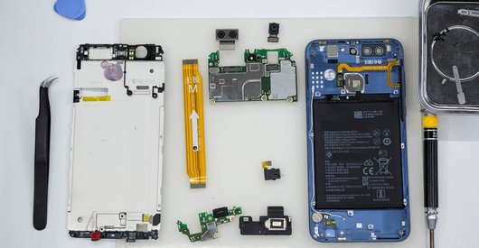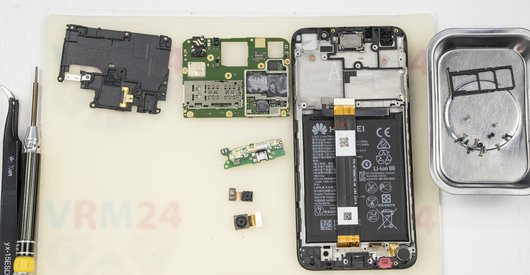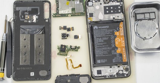
Recommended tools
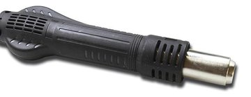
Heat gun
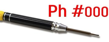
Screwdriver Phillips #000
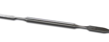
Opening tool / Spudger
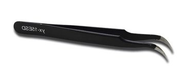
Tweezers
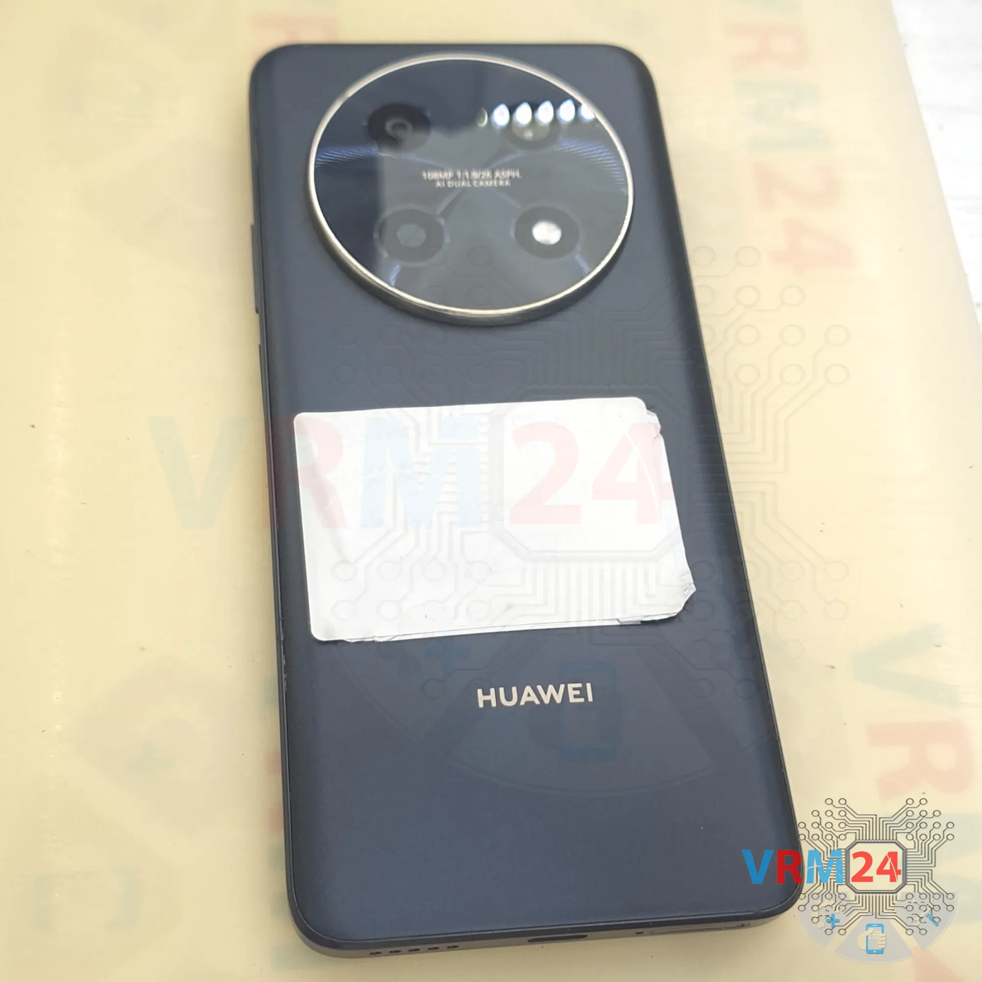
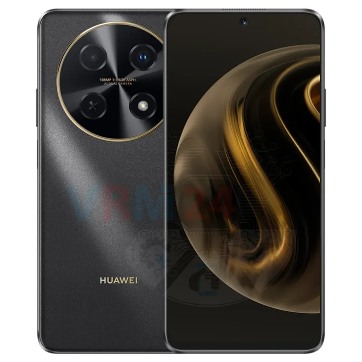
Disassembly/Repair of the mobile device Huawei Nova 12i (Huawei Nova 12i CTR-AL20) with each step description and the required set of tools.
5236
Views
2
Likes
—
Share
1
Questions

Step 1.
Before disassembling!
⚠️ Before disassembling, do not forget to turn your phone off.
Step 2.
Remove the tray
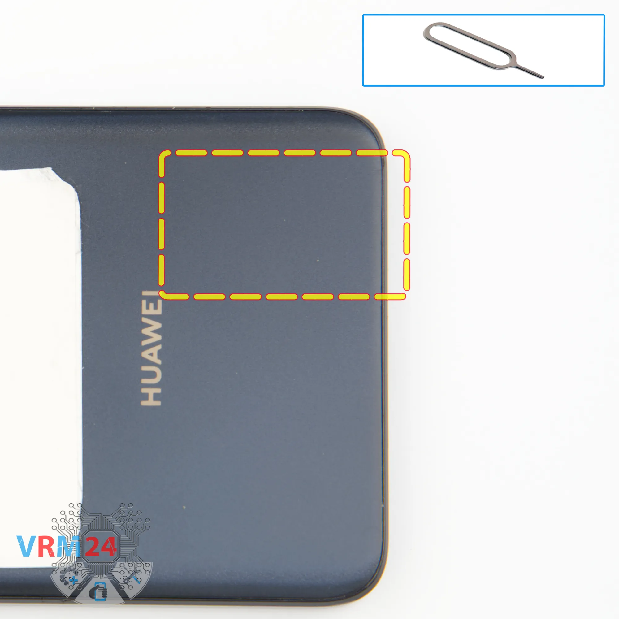
First, we need to remove the SIM card tray.
To do that, we use a special SIM eject tool.
Insert it into the pin hole and gently push the tray out.
If the tray doesn’t come out easily, you can use tweezers to help.
Step 3.
Open the back cover
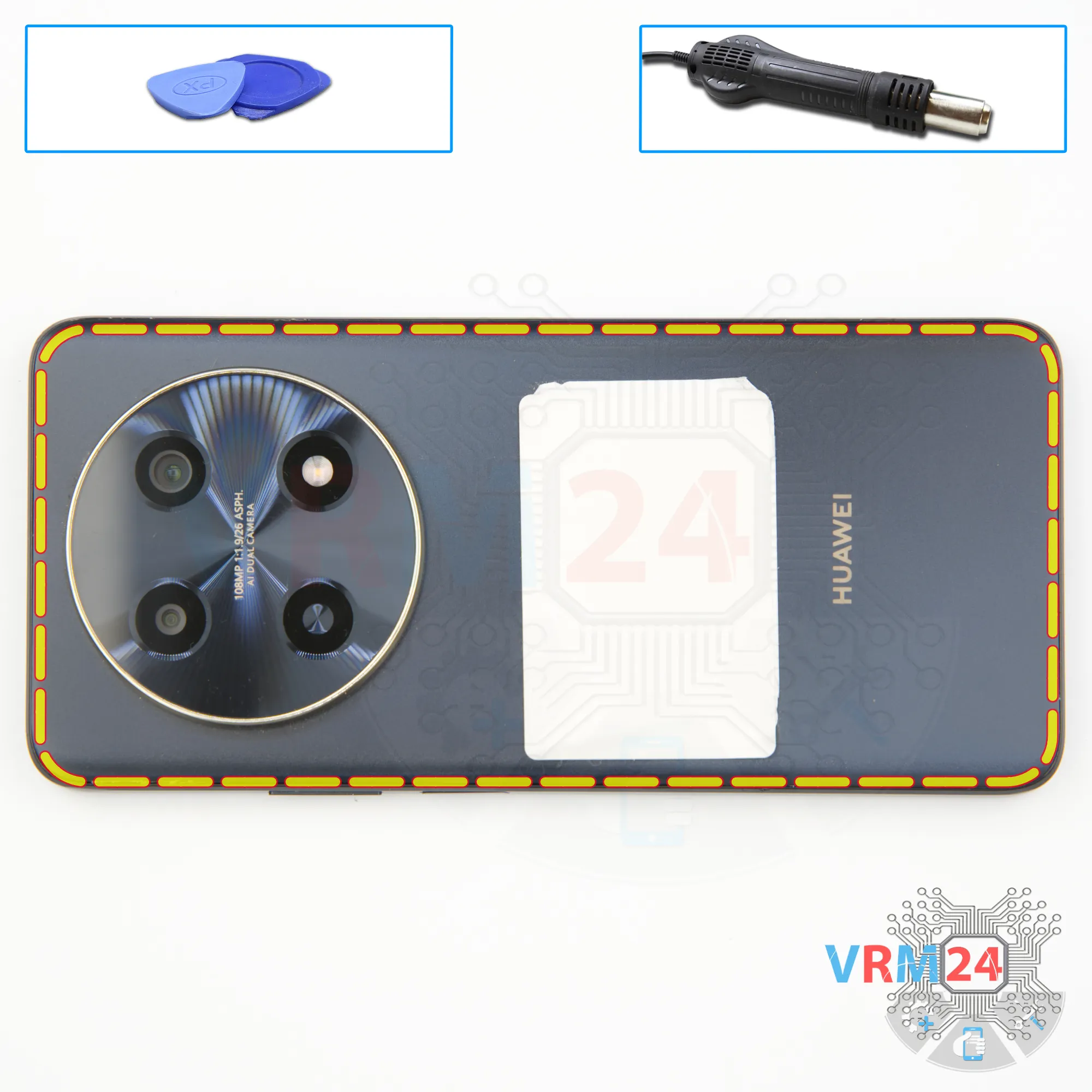
Next, we need to heat the back cover to approximately 70°C or 160°F.
We’re using a heating pad, but you can use a hair dryer instead.
After 5 to 7 minutes, we can move on to removing the back cover.
To separate the back cover, we use a thin plastic film.
Gently insert it into the gap between the back cover and we slide the plastic film along the edge, cutting through the adhesive.
Step 4.
Unscrew the screws
Next, we need to cover the camera lenses to prevent dust from getting inside.
We’re using a special protective film for that.
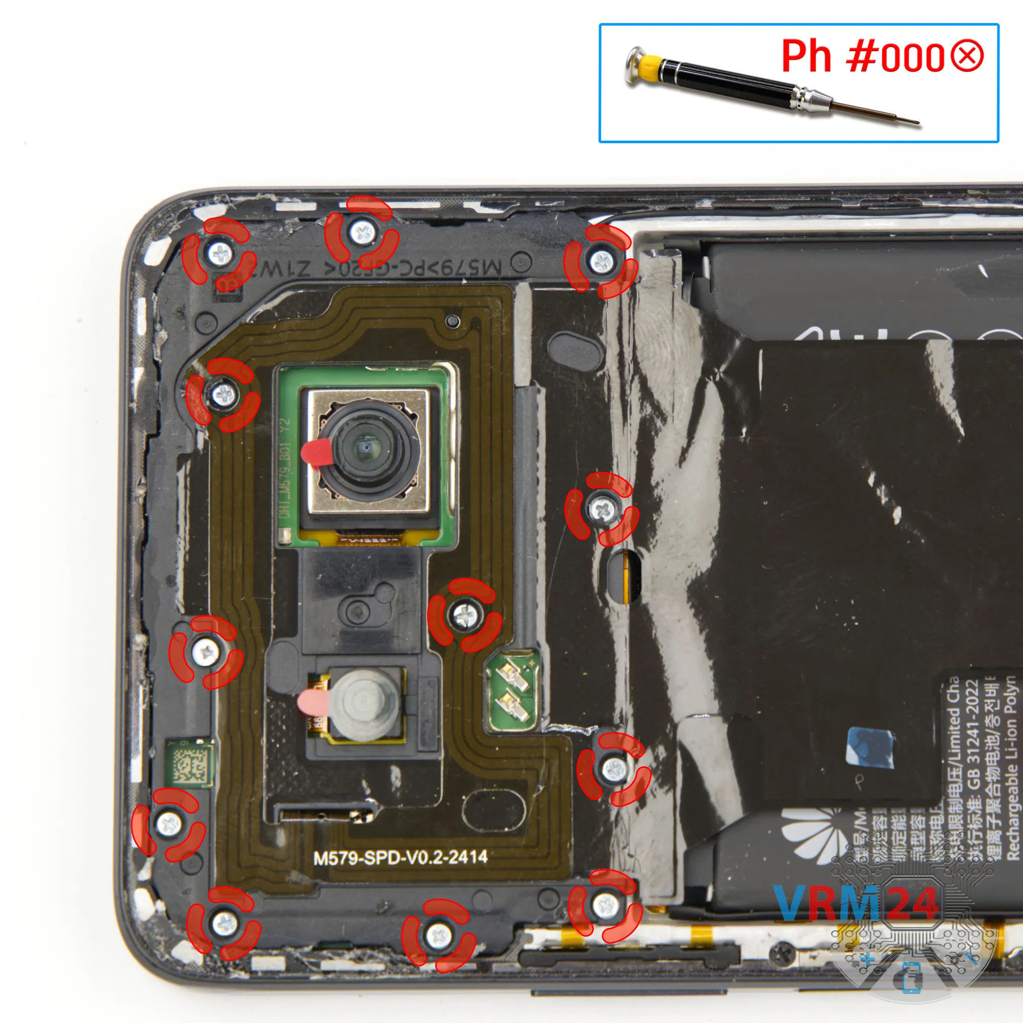
We’ve covered the camera lenses, so now we can move on to removing the screws in the top section.
For this, we use a 1.5 mm Phillips screwdriver or a #000 bit.
Carefully unscrew the screws and place them on a dedicated surface.
It’s best to arrange them in a specific order to avoid mixing them up during reassembly.
Sometimes, screws don’t fit properly into different holes— so keep track of where each one came from.
Step 5.
Open the cover
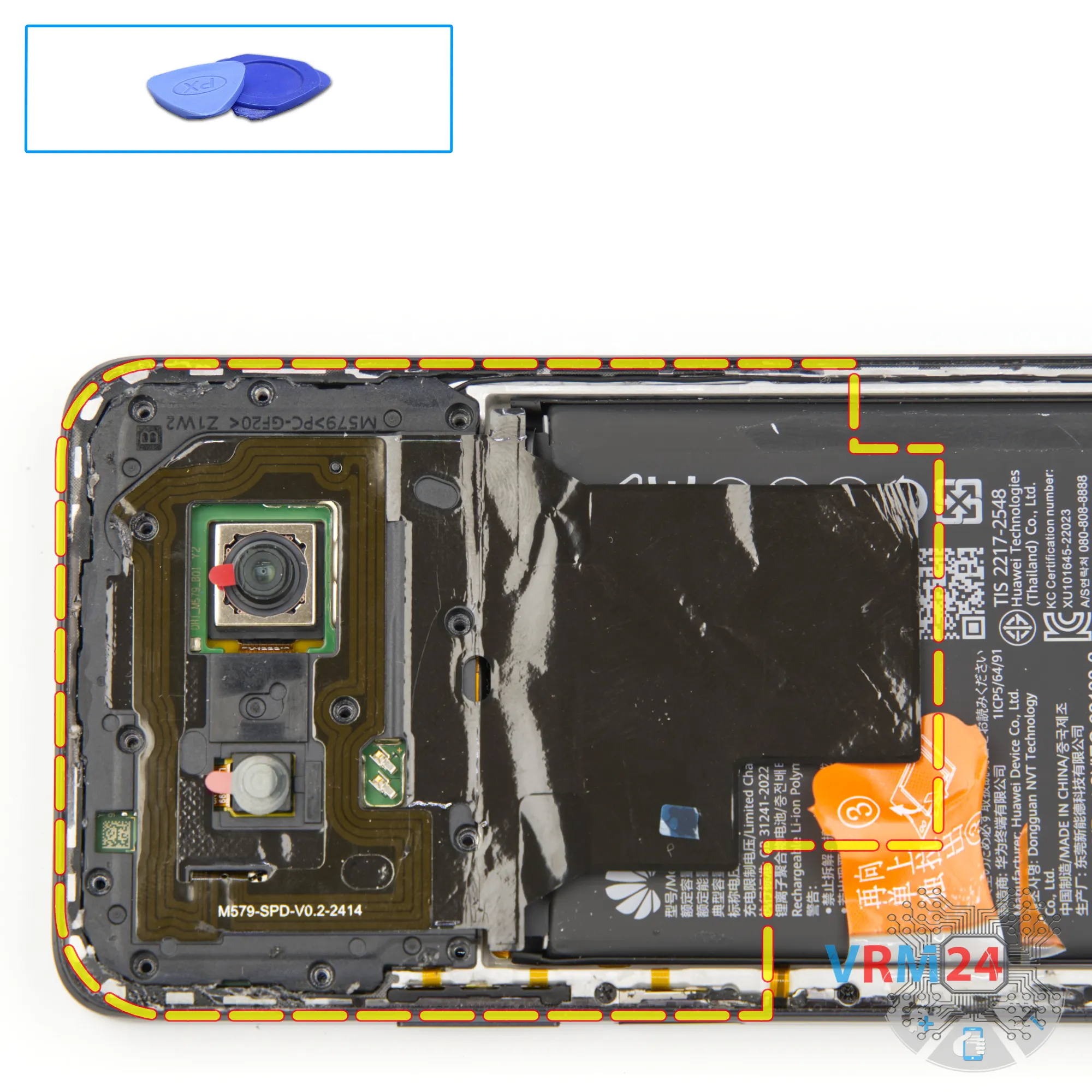
Next, we need to remove the top cover. Use a non-metal tool and gently try to lift the cover.
Note:
For models like this, which have a lot of small openings, it’s not recommended to use sealant when reattaching the back cover.
Sealant can seep into the holes and make it difficult to remove the covers later on.
Plus, it can end up sticking to all kinds of components inside the phone.
Step 6.
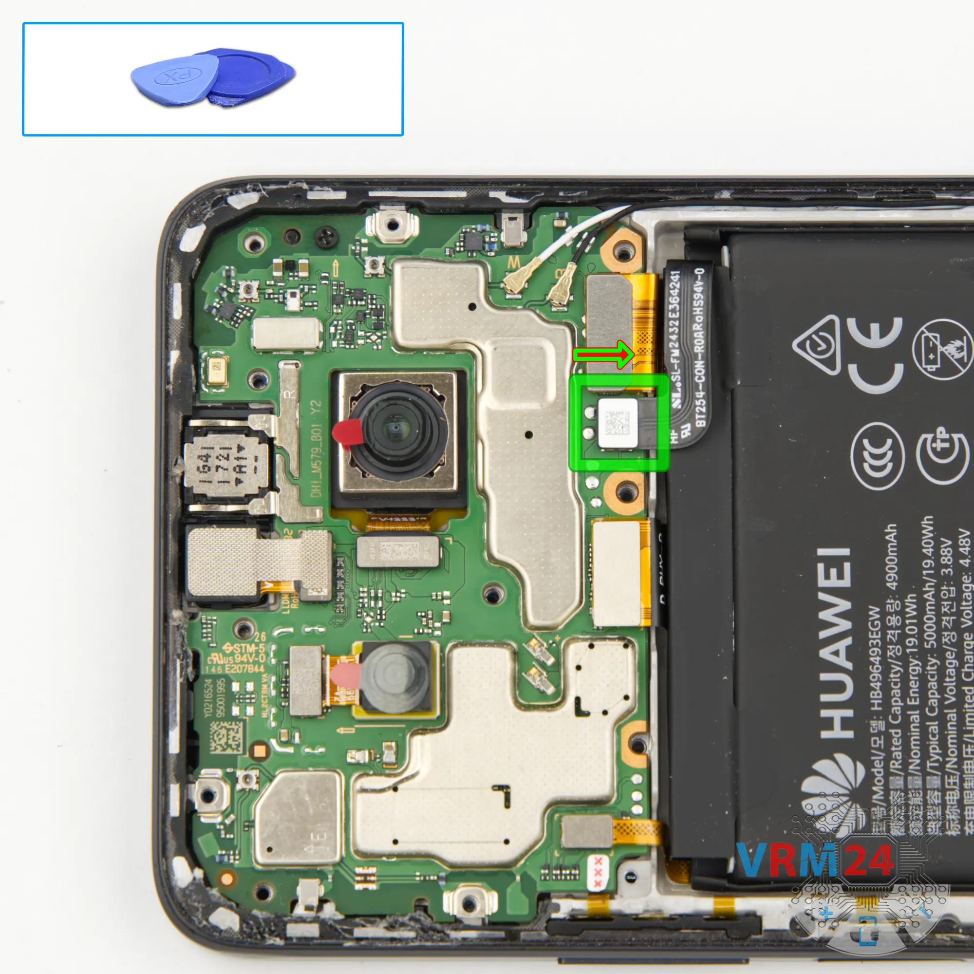
Disconnect the battery connector
Next, we disconnect the battery connector using a non-metal tool.
ℹ️ The Huawei Nova 12i model has a battery HB496493EGW with a capacity of 5000 mAh (also known as a rechargeable battery).
Step 7.
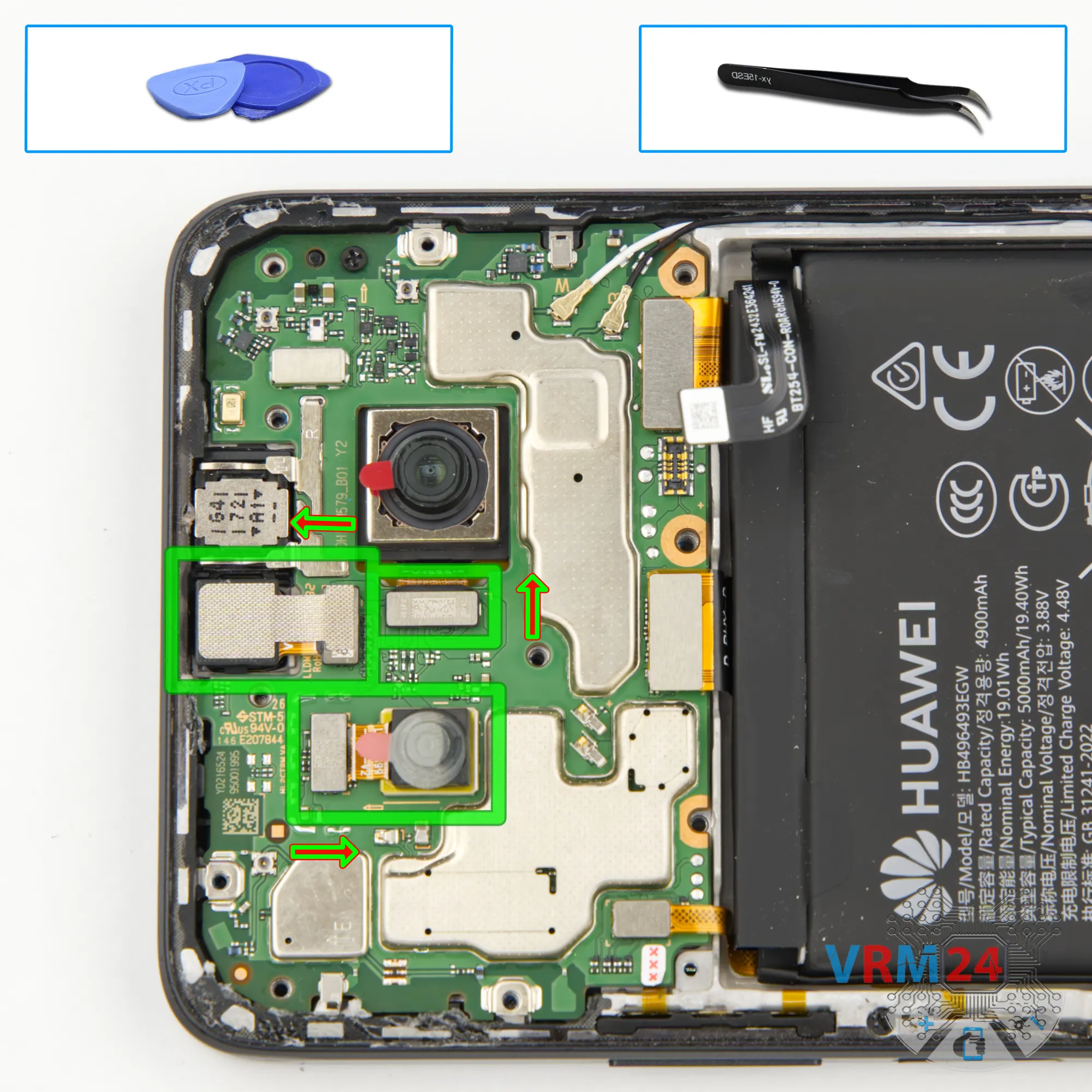
Remove the cameras
We can try to remove the large camera, but for some reason it’s not coming off — so we’ll take it out later if needed.
Next, we disconnect the small rear-facing camera and carefully set it aside.
We also remove the front-facing camera— and set that aside as well.
Step 8.
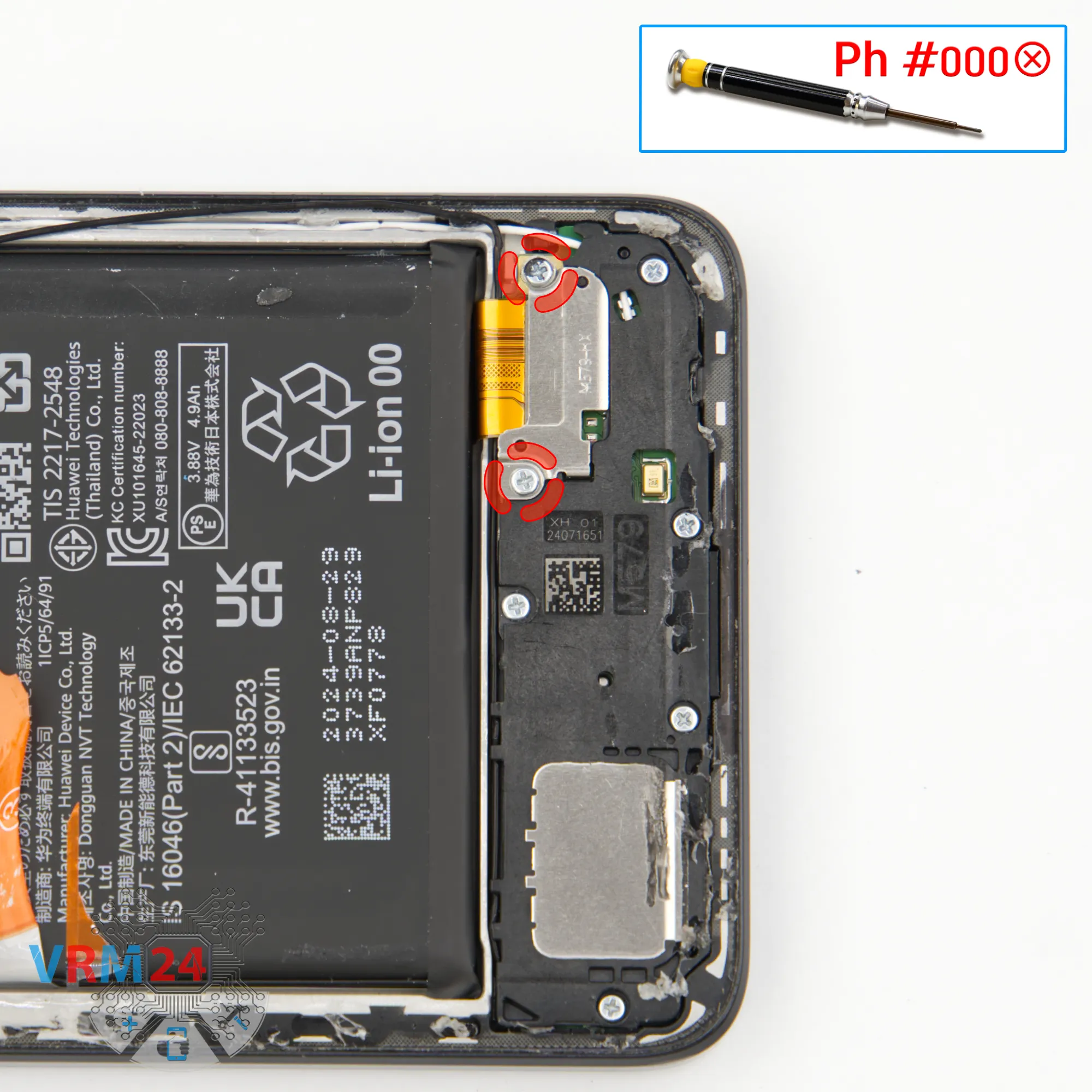
Unscrew the screws
And we move on to removing the screws in the bottom section. Here, again, we use a 1.5 mm Phillips screwdriver to unscrew the two screws.
Step 9.
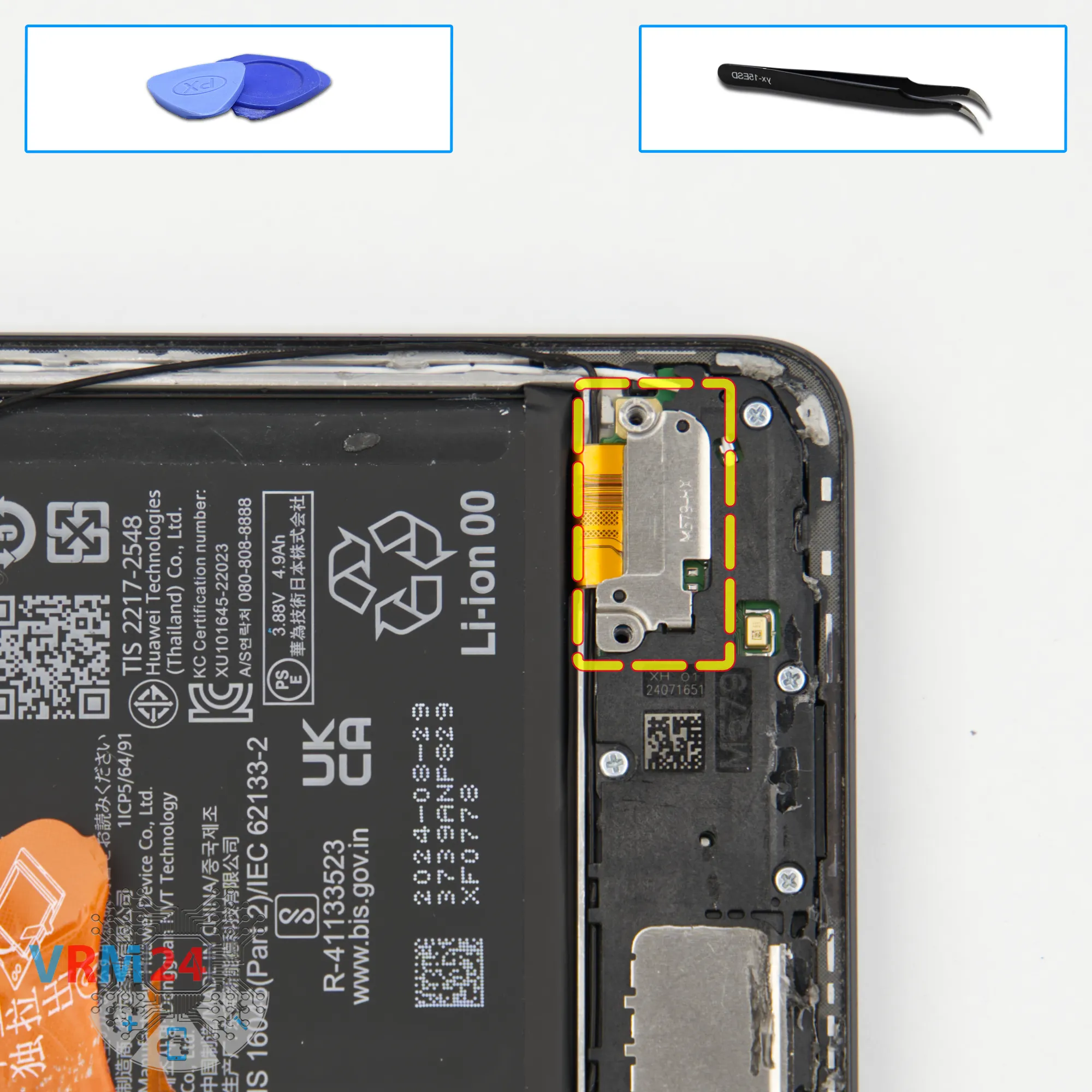
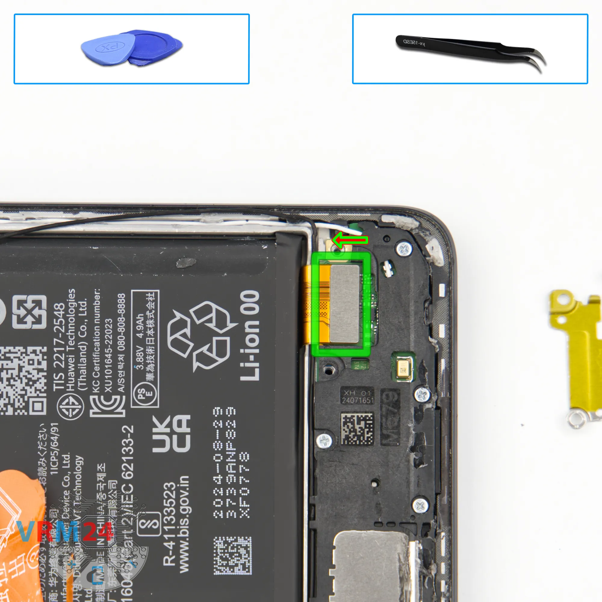
Remove the bracket
We can carefully remove the bracket holding the connector.
Step 10.
Disconnect the connector
Now we can disconnect the inter-board cable connector.
Step 11.
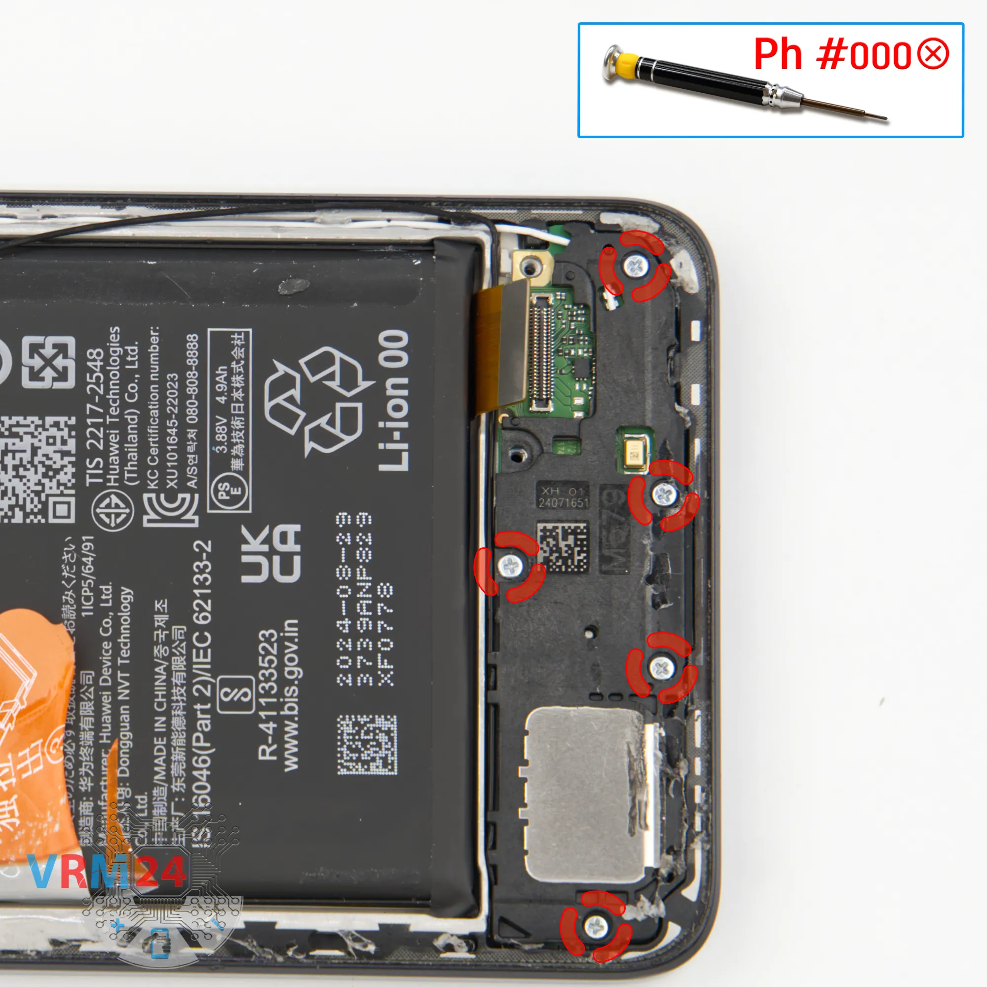
Unscrew the screws
Here, again, we use a 1.5 mm Phillips screwdriver or #000 bit to unscrew the five screws.
Step 12.
Remove the loudspeaker
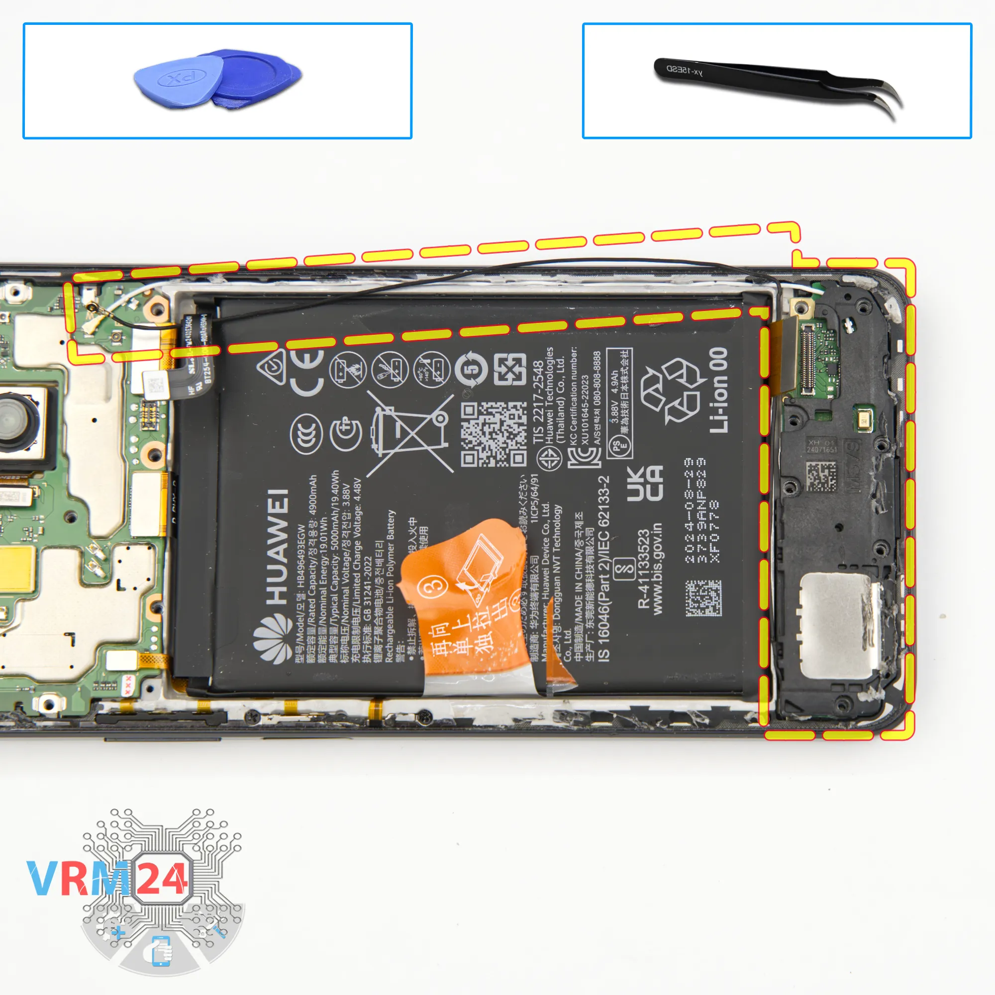
After removing the screws, we need to detach the speaker module.
Gently lift from the correct spot and separate the speaker block.
Now we carefully disconnect the speaker module, flip it over, and we can see that the coaxial cable is connected to a small antenna board on this module.
So, it’s best to first disconnect the inter-board flex cable, free the coaxial cable from its channel, then unplug its connector from the mainboard, and set the speaker block, antenna board, and coaxial cable aside.
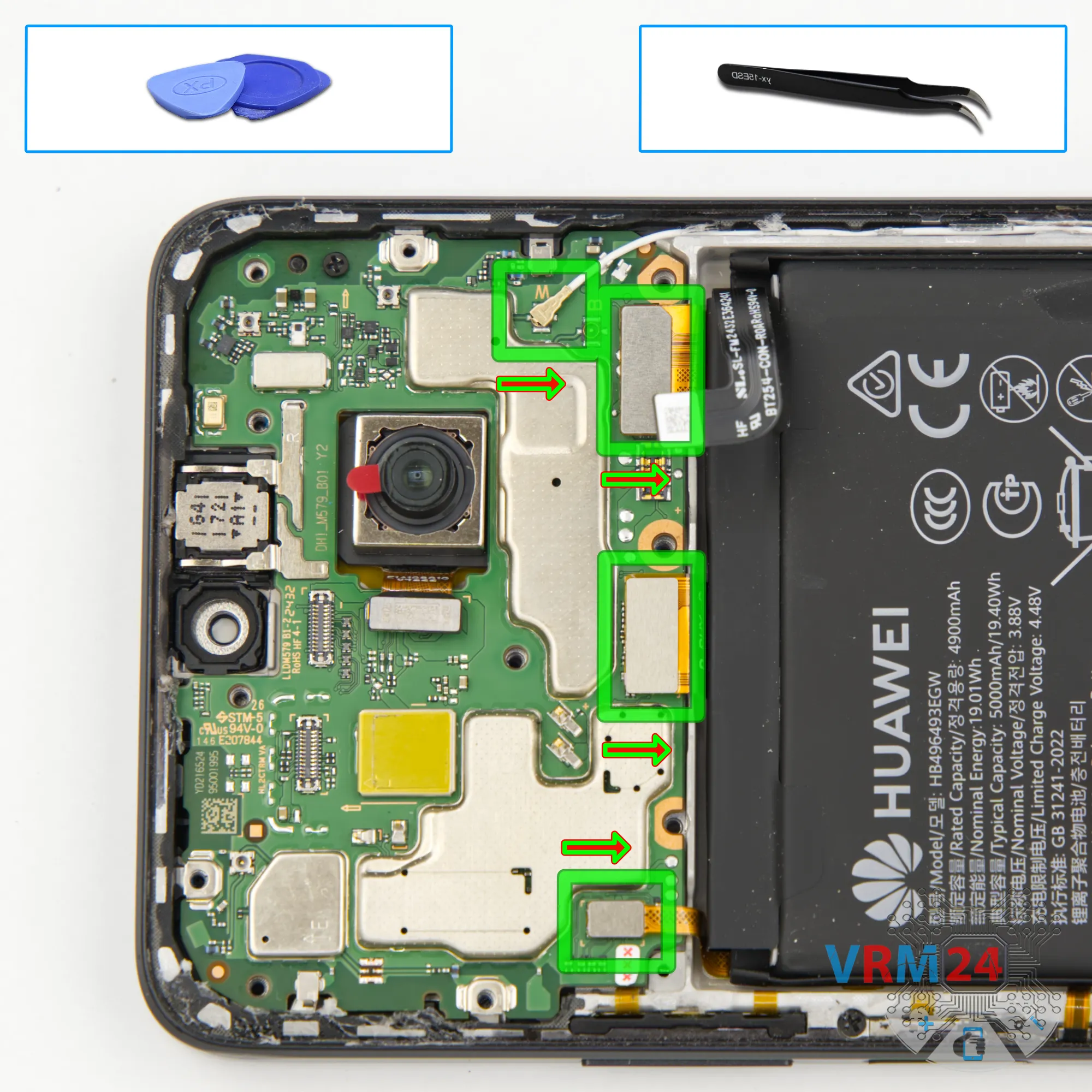
Step 13.
Disconnect the connectors
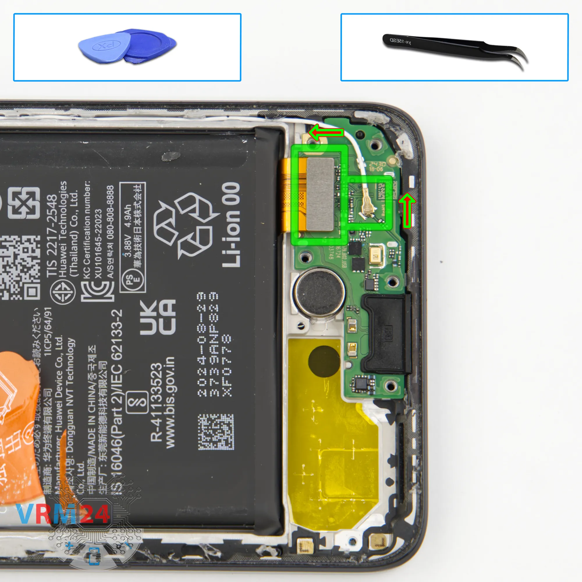
Next, we need to disconnect the coaxial cable connector on the sub-board.
If you forgot to disconnect the inter-board connector, now is your best chance.
Carefully disconnect the plug, release the cable, and now we can remove the sub-board.
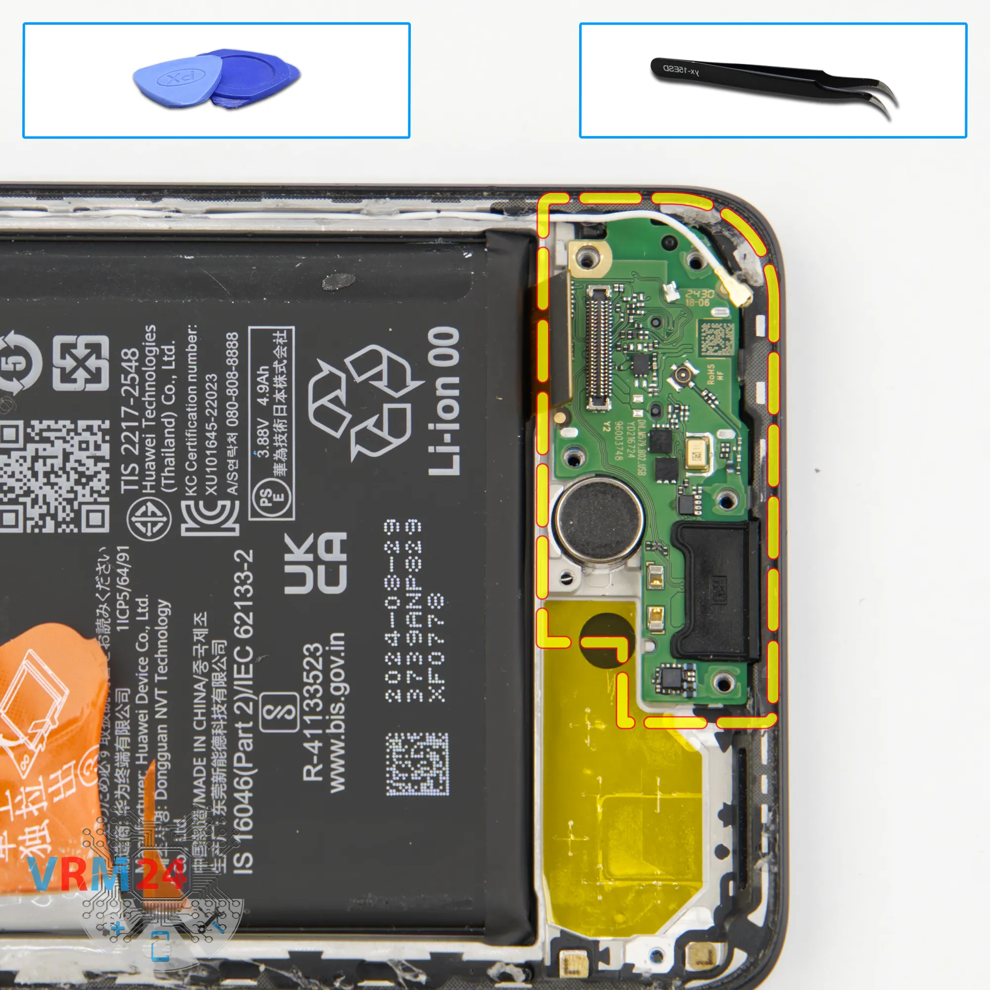
Step 14.
Remove the sub-board
Now we can remove the sub-board.
Lift it from the correct spot and take it out.
On the sub-board, we have the charging port, microphone, and the SIM card connector on the reverse side.
Step 15.
Disconnect the connectors
On the motherboard, first, we need to disconnect the connectors.
Unplug the display flex cable, then the inter-board flex cable, and finally the sensor and side button flex cable.
Step 16.
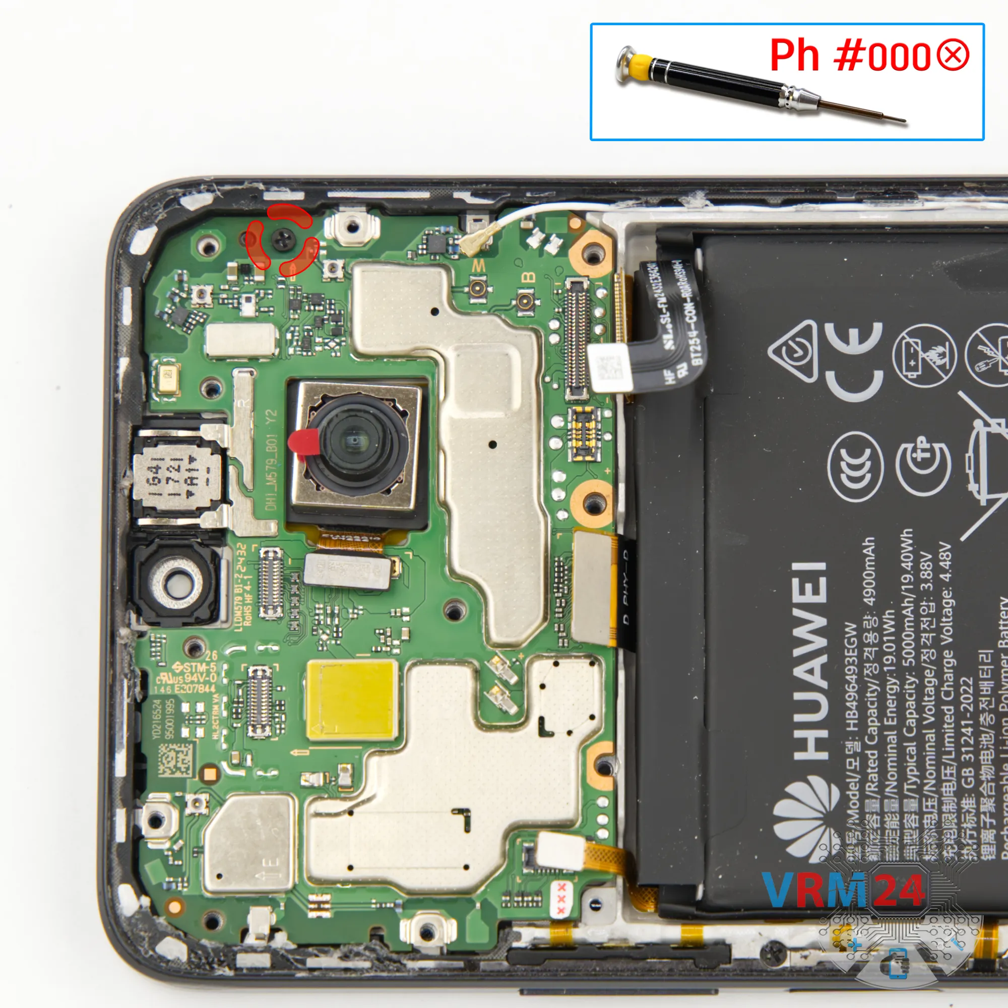
Unscrew one screw
Next, unscrew the single screw holding down the mainboard.
Note:
this screw is different from the others, so keep it separate.
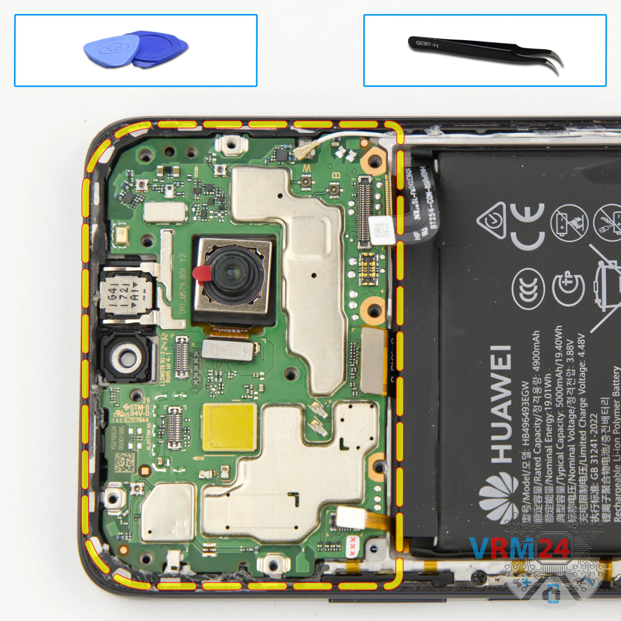
Step 17.
Remove the motherboard
Carefully remove the printed circuit board. There is no need to use a lever or try to reach the circuit board by force. Make sure that nothing is getting in the way or holding the circuit board.
The motherboard, also, may be attached with attachments like latches or hooks, be careful.
⚠️ Do not bend the circuit board when removing it or push tools under it. Unbeknownst to yourself, you can damage components or cables from the inside.
Step 18.
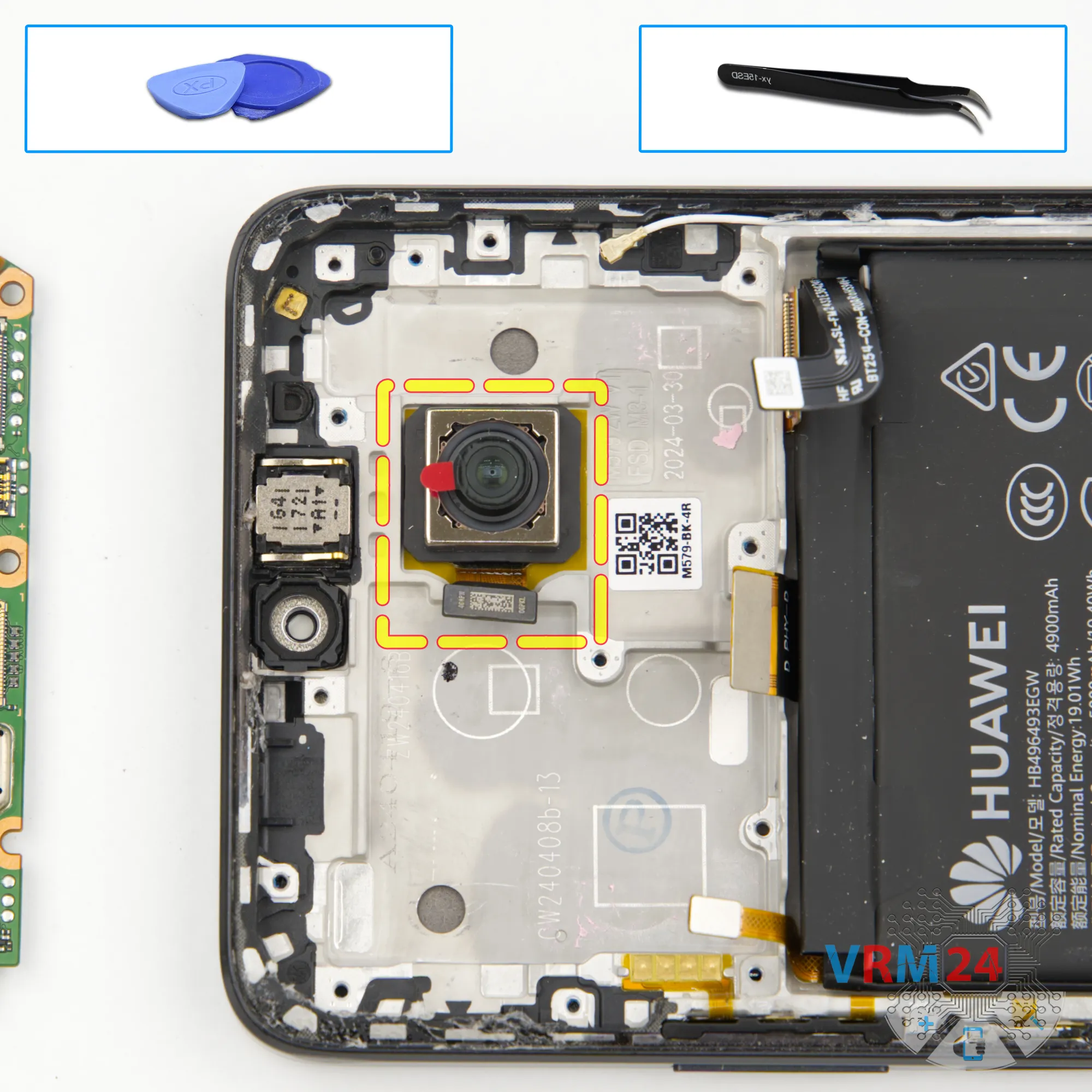
Remove the rear camera
Now we can remove the main rear camera.
Step 19.
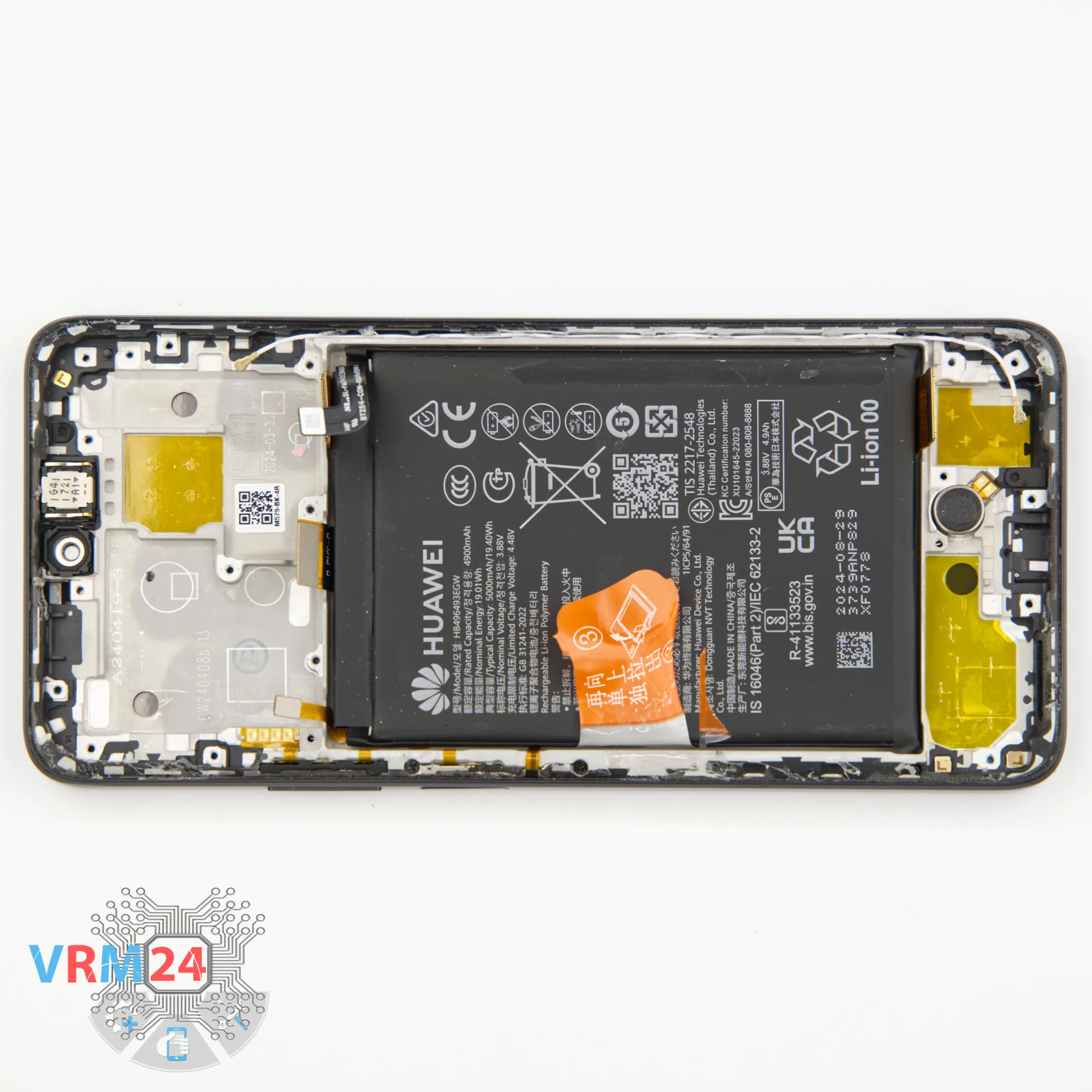
In the display frame remained
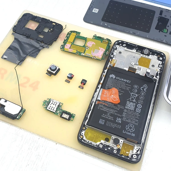
ℹ️ In the display frame remained: the earpiece speaker, battery, and vibration motor.

If you have a question, ask us, and we will try to answer in as much detail as possible. If this article was helpful for you, please rate it.

5236
Views
2
Likes
—
Share
1
Questions
Related Instructions
Related Reviews
Related Blog


Top instructions
Check our
Top Huawei instructions most liked by readers
New instructions
Check our
New Huawei brand instructions on vrm24.com