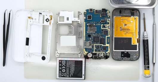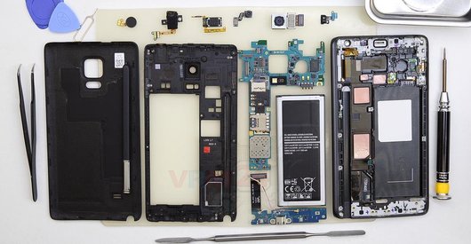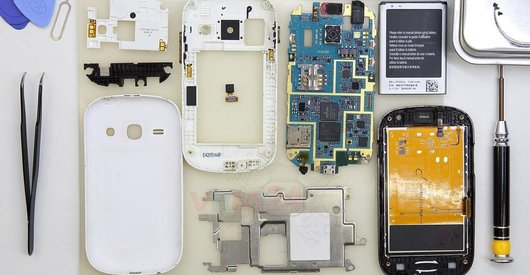
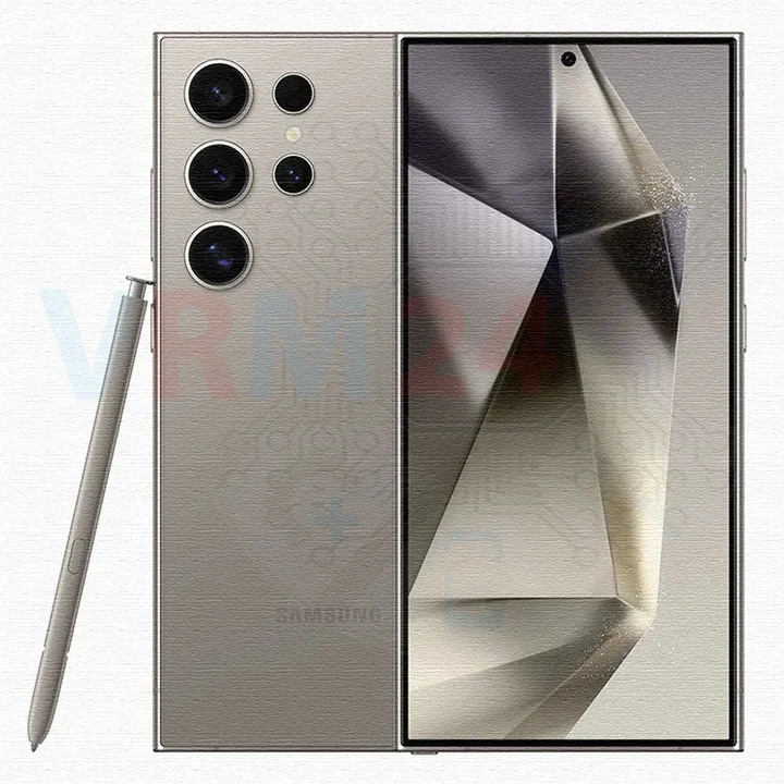
Recommended tools
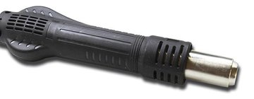
Heat gun
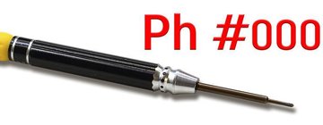
Screwdriver Phillips #000
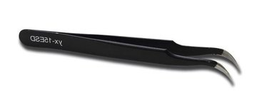
Tweezers
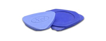
Non-metallic tool
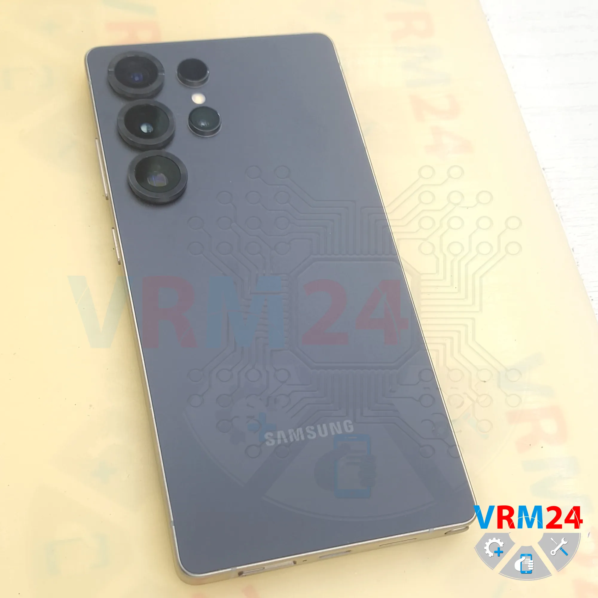
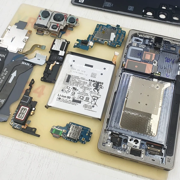
Disassembly/Repair of the mobile device Samsung Galaxy S25 Ultra SM-S938 (Samsung Galaxy S25 Ultra SM-S938B, SM-S938B/DS, SM-S938U, SM-S938U1, SM-S938W, SM-S938N, SM-S9380, SM-S938E, SM-S938E/DS) with each step description and the required set of tools.
4873
Views
4
Likes
—
Share
0
Questions

Step 1.
Before disassembling!
⚠️ Before disassembling, do not forget to turn your phone off.
Step 2.
Remove the tray
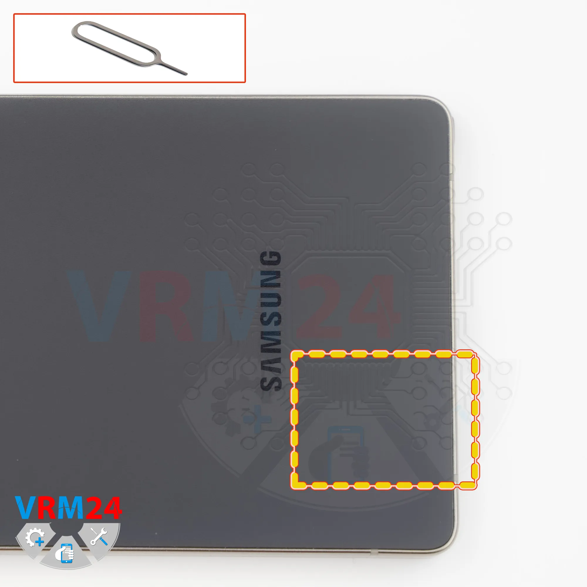
First of all, we need to remove the card tray.
To do this, we use the dedicated SIM eject tool.
Push the tray out and set it aside.
If you use, for example, a needle or a paper clip, you can damage the tray or the hole.
As a result, the tray may get stuck and you’ll have to go to a repair shop.
Step 3.
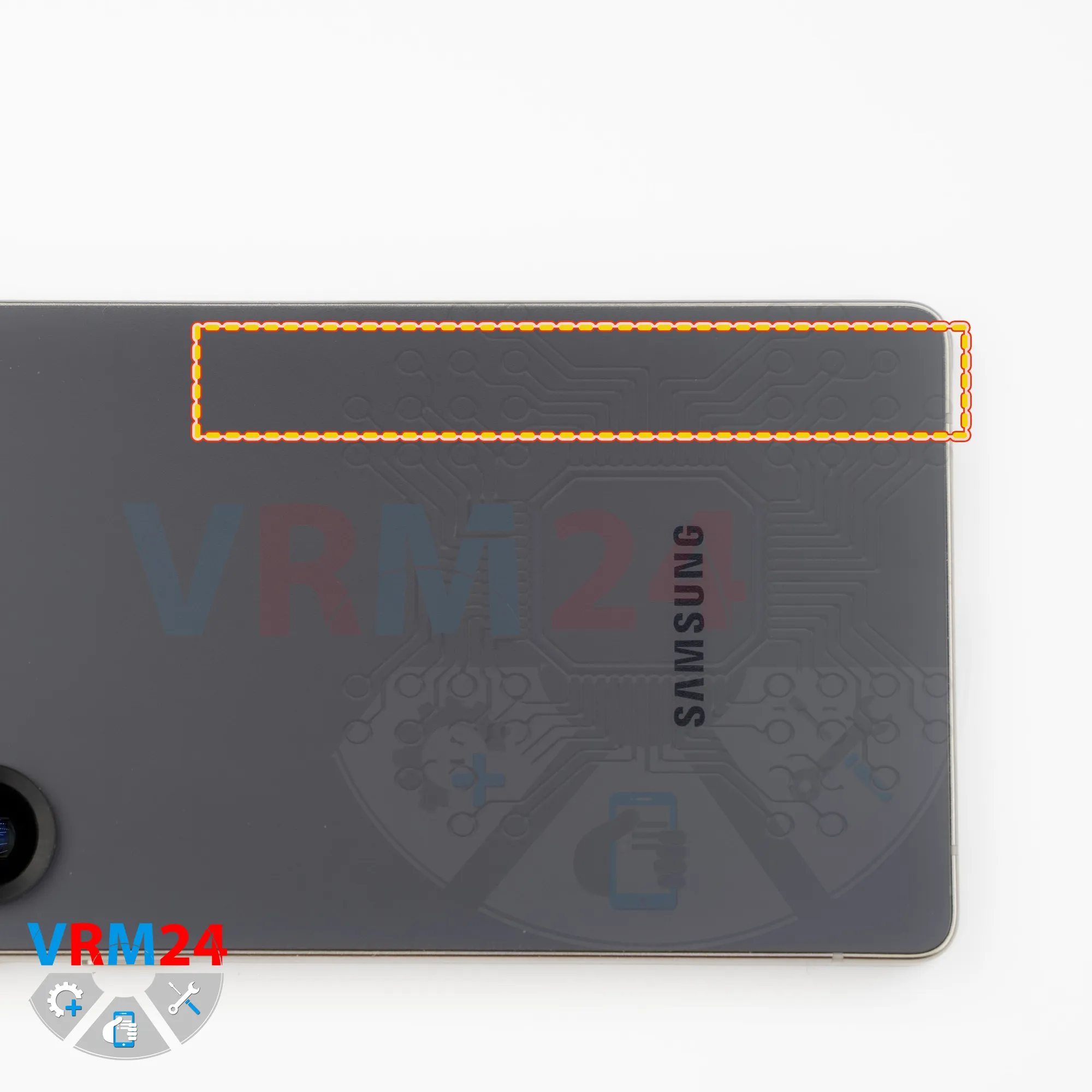
Remove the stylus pen
We also need to remove the stylus (S pen) so it doesn’t get in the way.
Step 4.
Open the back cover
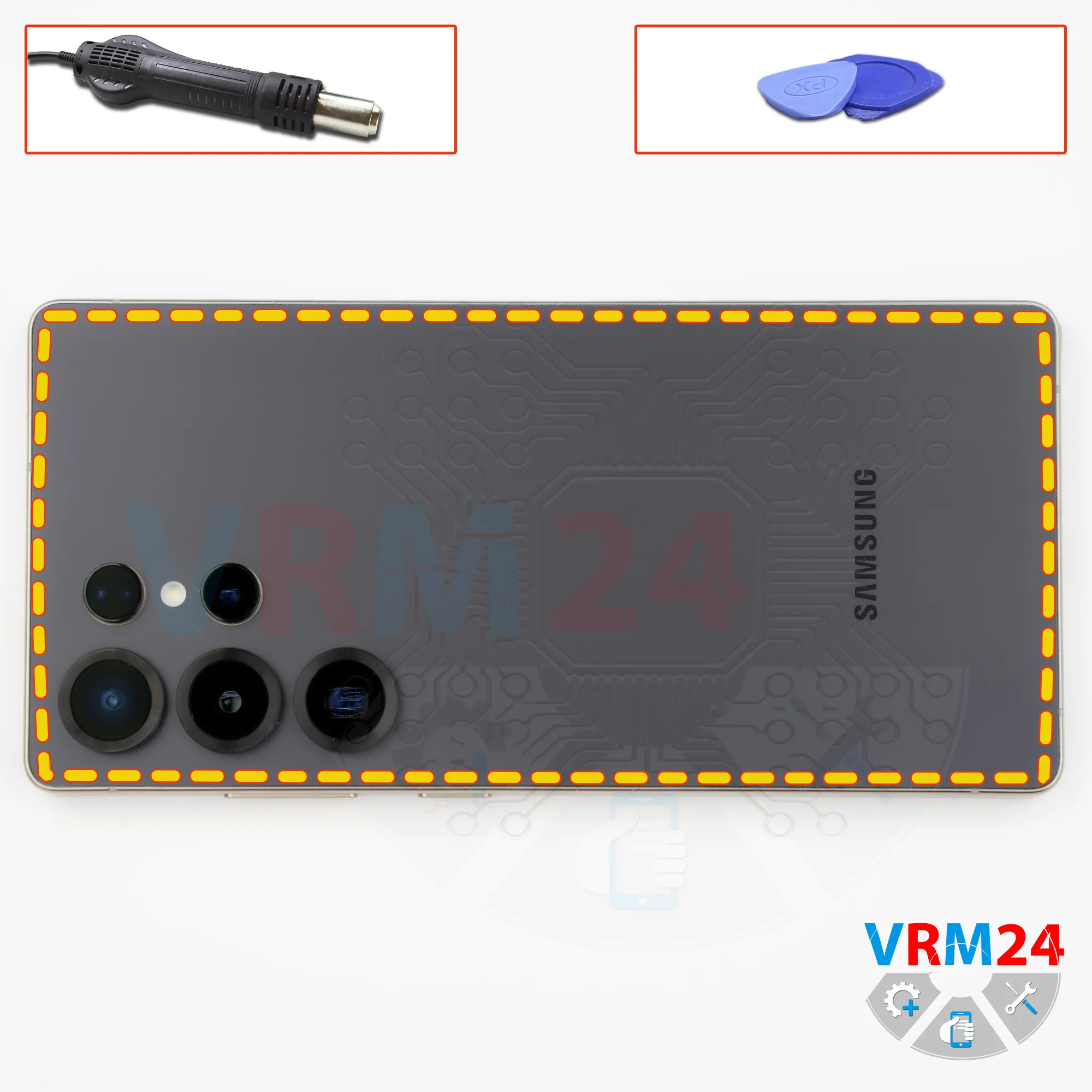
Next, we heat the surface of the back cover to approximately 70°C (about 160°F). For this, we use a heating mat, but you can also use a hair dryer.
Then we can move on to separating or peeling off the back cover.
To remove the back cover, we use a thin plastic film. Insert it into the gap between the back cover and the midframe and carefully run it along the edge, cutting through the adhesive.
As always, you need to be careful around the side buttons, because there may be flex cables located there.
You also need to be careful around the cameras so you don’t accidentally touch or damage the lenses.
Don’t rush and don’t use force, so you don’t accidentally damage anything.
Step 5.
Unscrew the screws
Next, we need to protect the camera lenses.
For this, we use a special protective film.
Please note that we apply the film not on the lenses themselves, but on the rim around them.
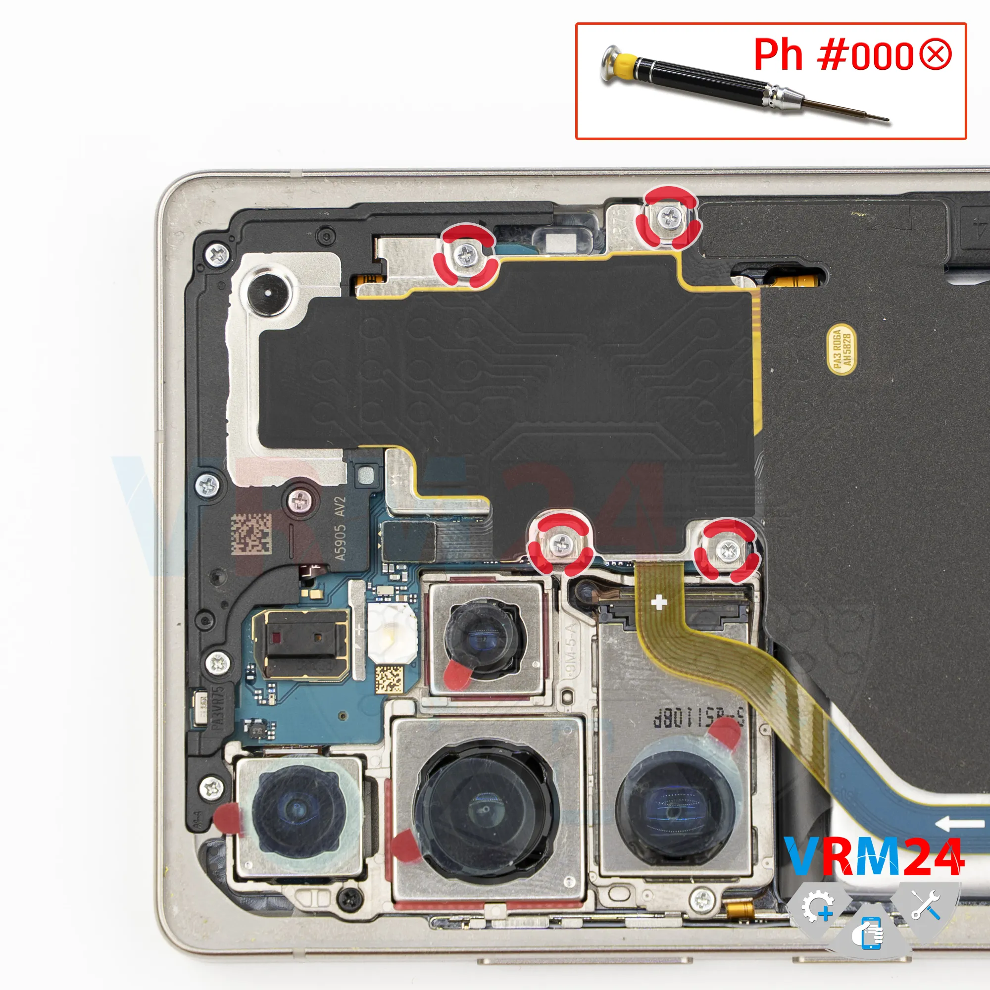
After that, we need to remove some of the screws in the upper section.
For this, we use a Phillips screwdriver, 1.5 mm, or Phillips #000.
Step 6.
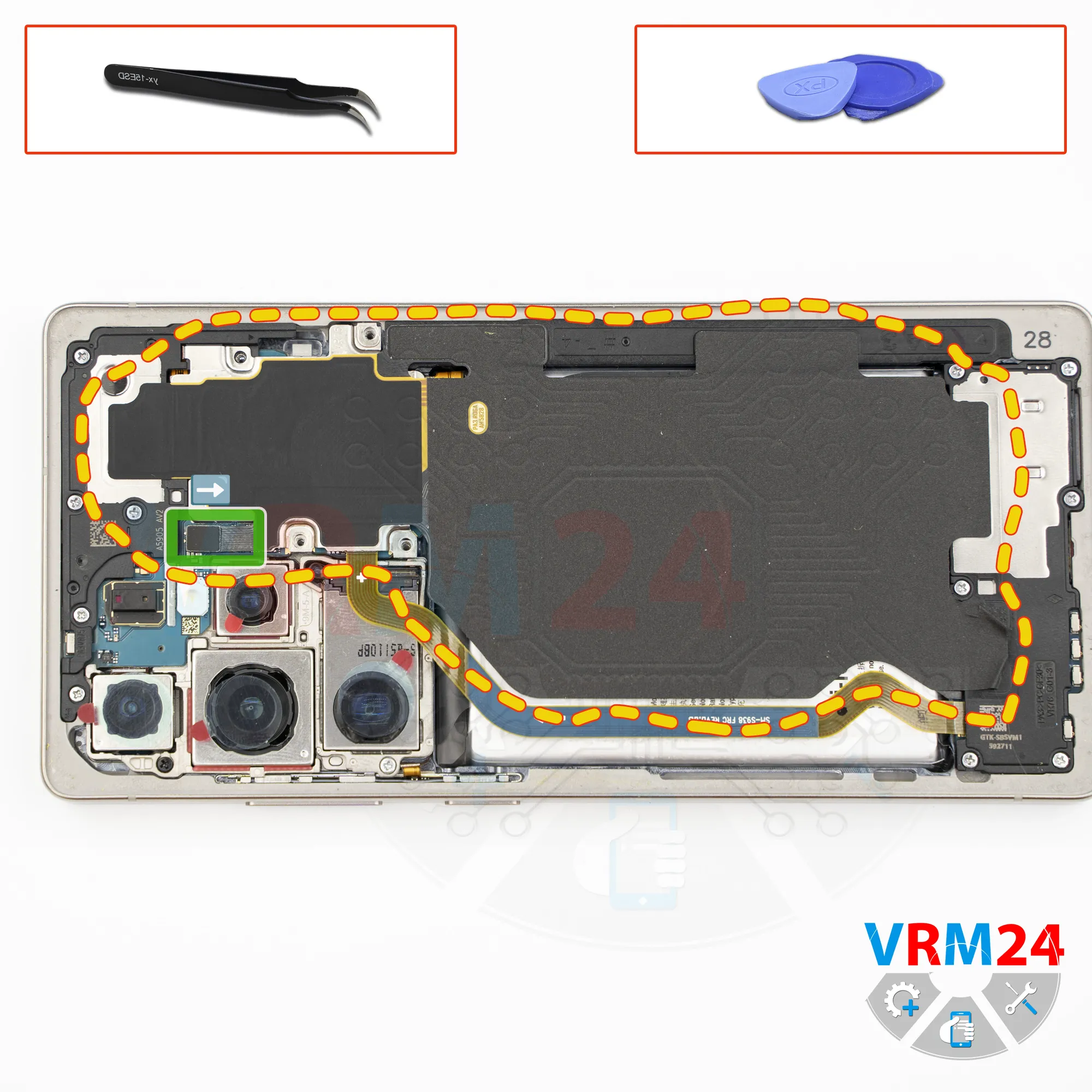
Remove the wireless charging
Then, using a non-metal tool, we disconnect the wireless charging and NFC connector and set this assembly aside.
Step 7.
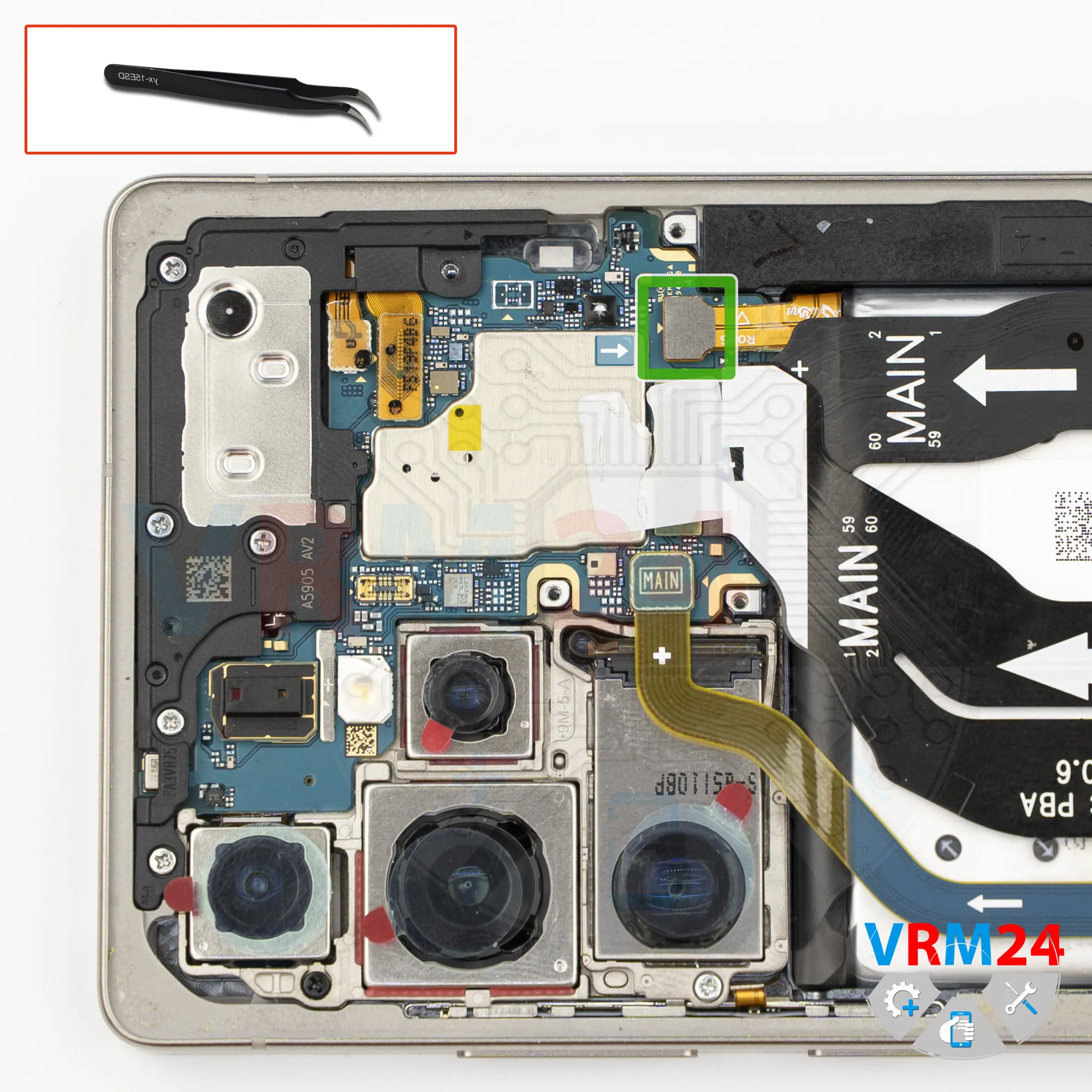
Disconnect the battery connector
After that, also using a non-metal tool, we disconnect the battery connector.
ℹ️ Samsung Galaxy S25 Ultra model SM-S938 uses a EB-BS938ABY rechargeable battery with a capacity of 5000 mAh.
Step 8.
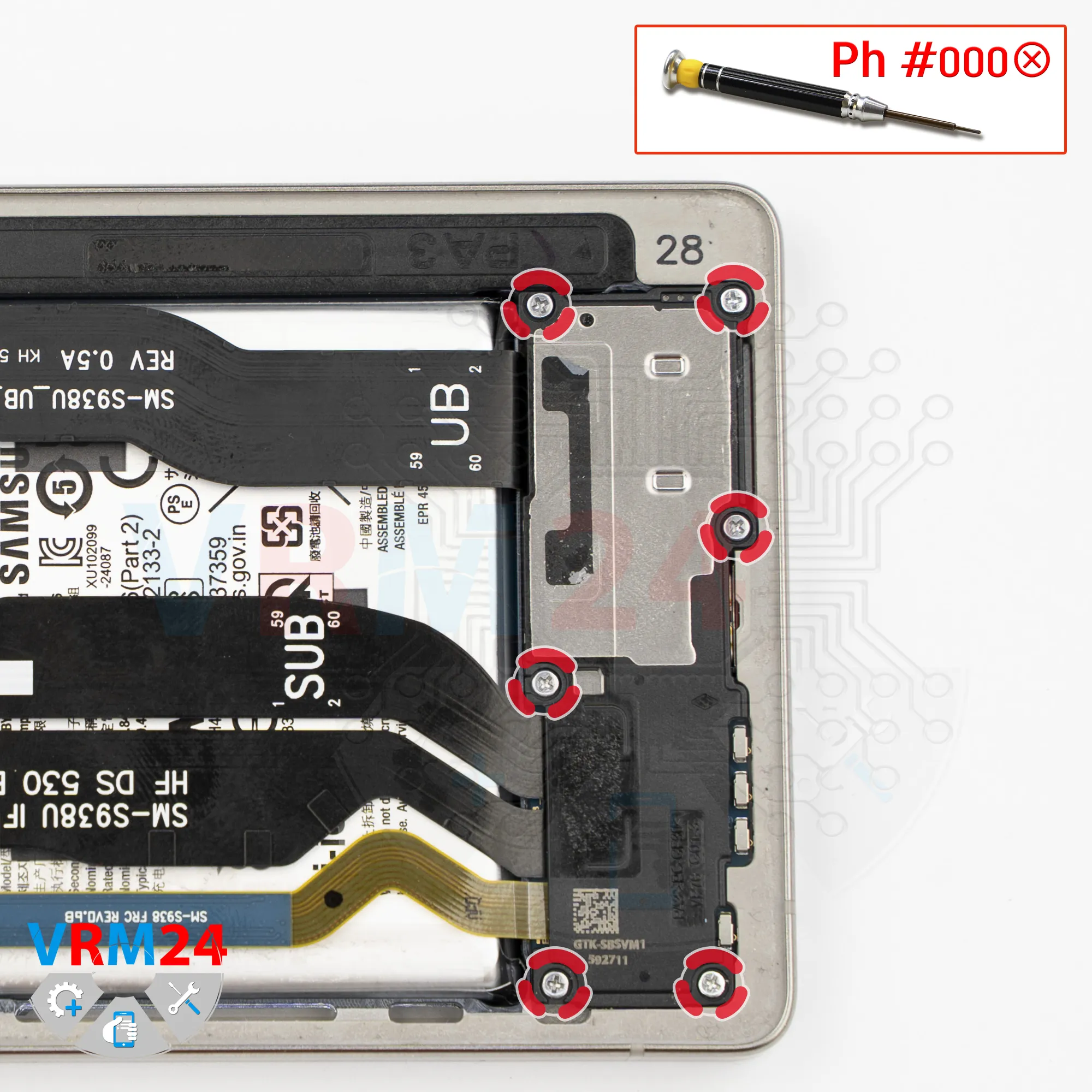
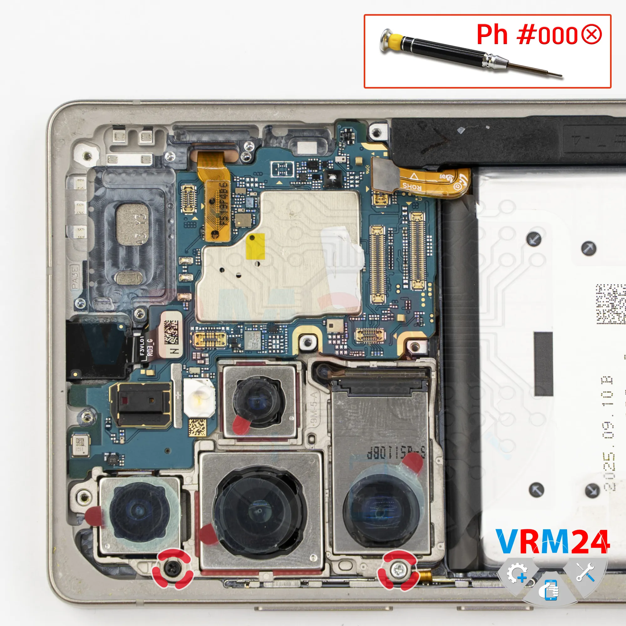
Unscrew the screws
In the lower section, we also need to remove screws. For this, we again use a 1.5 mm Phillips screwdriver.
Remove the screws and place them on a separate surface, separate from the previous ones.
Step 9.
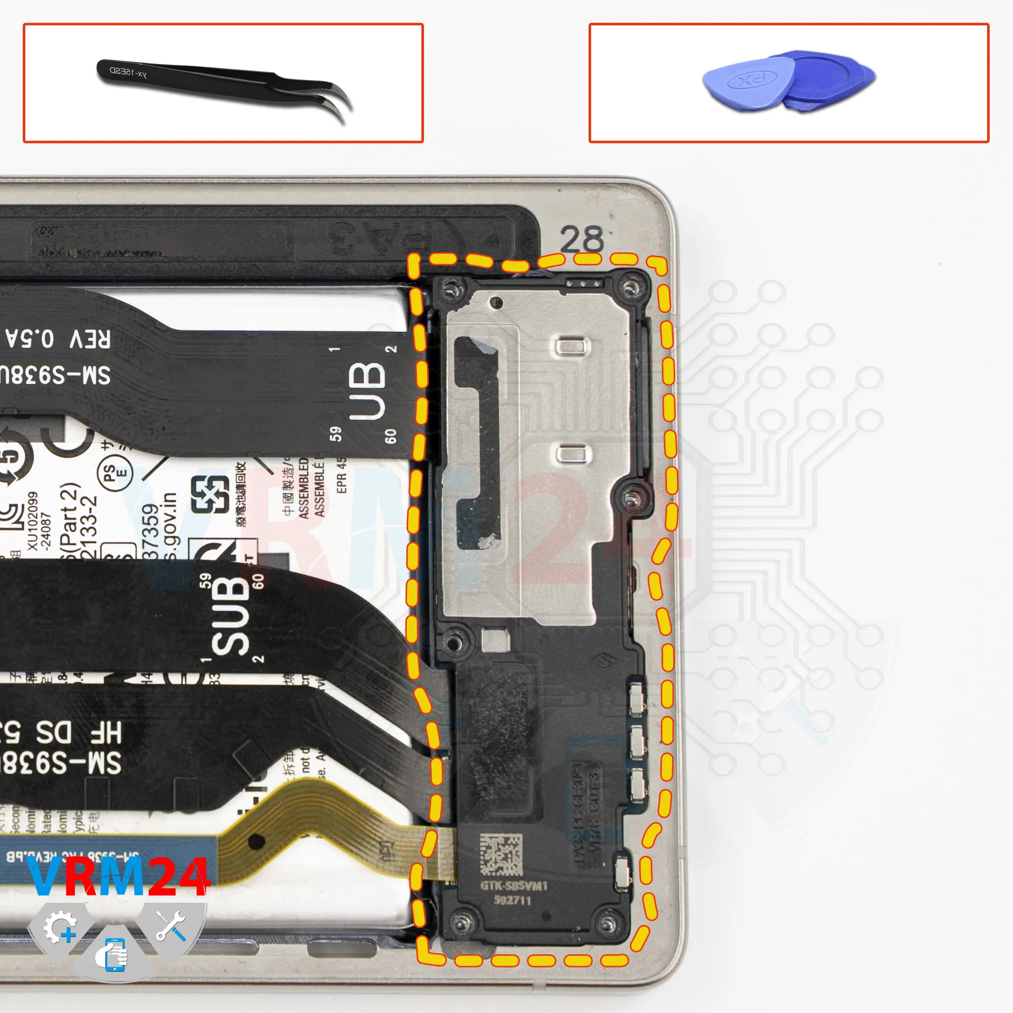
Remove the loudspeaker
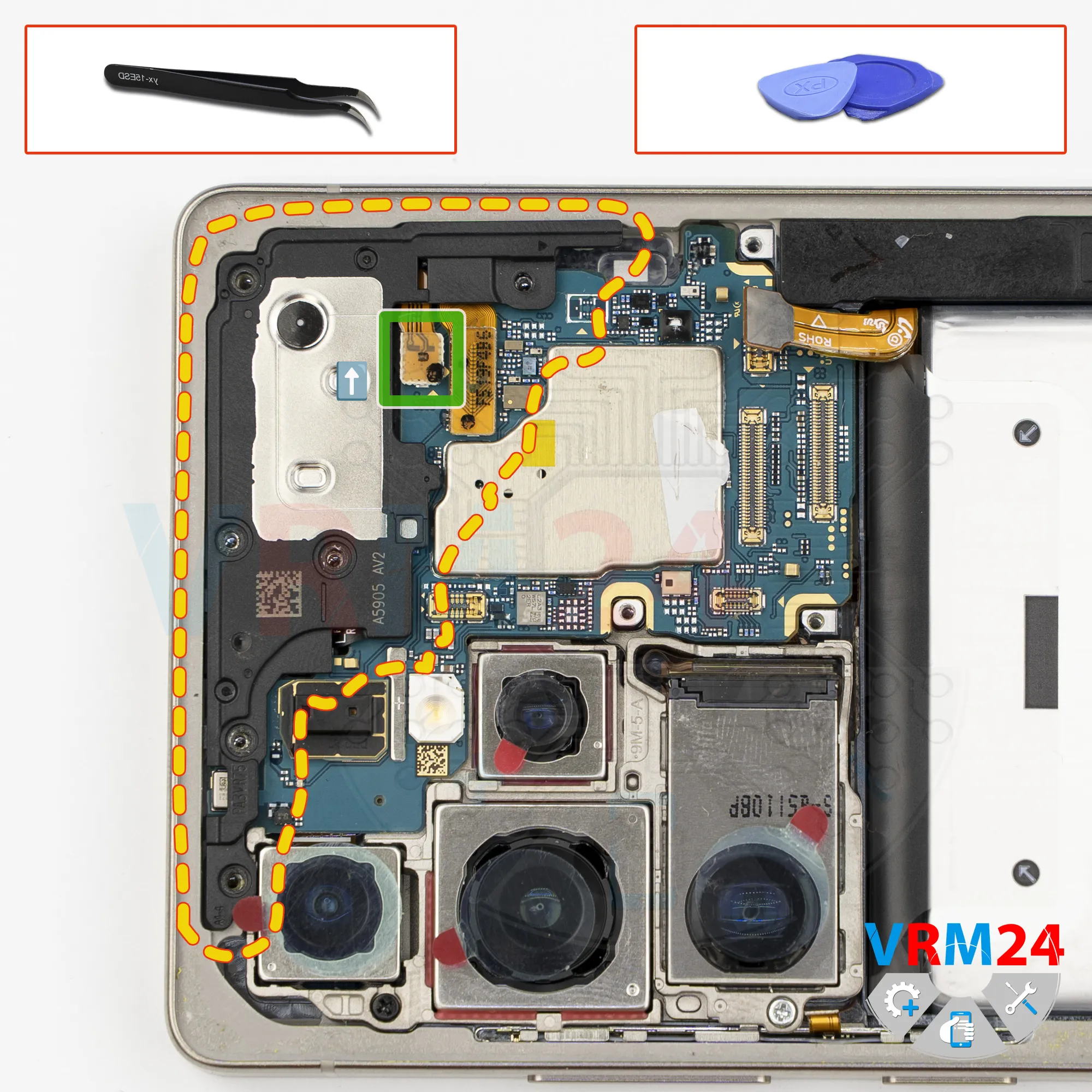
Next, we need to remove the cover, most likely with the loudspeaker.
At the correct spot, carefully pry it up and try to lift it.
On new Samsung models, an arrow usually indicates the direction in which the covers should be removed.
Step 10.
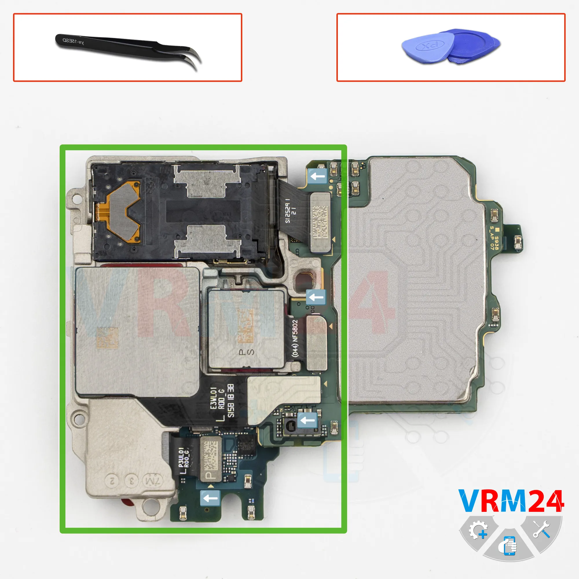
Remove the interconnect cables
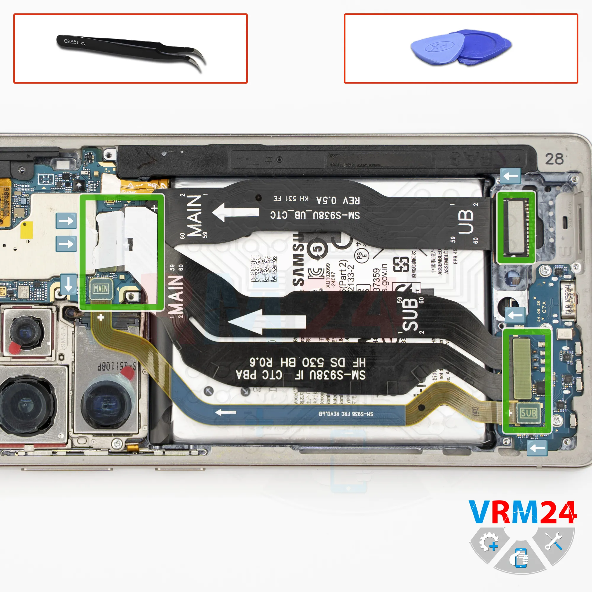
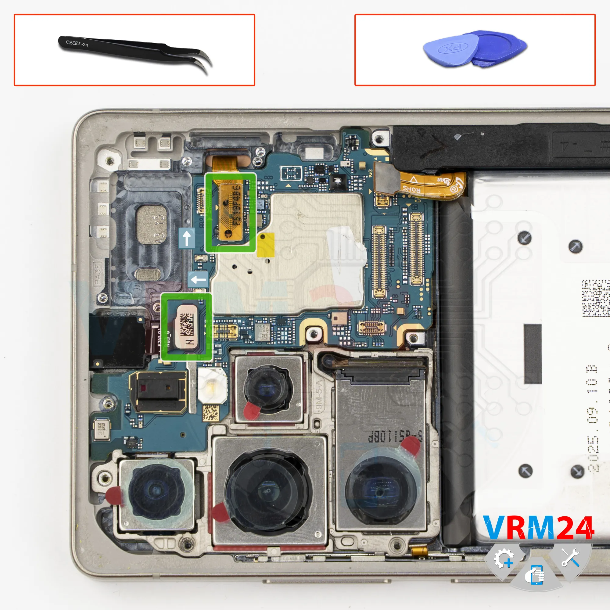
Then we disconnect the interconnect flex cable connectors.
Carefully disconnect the connectors.
The narrowest cable is usually the antenna cable, formerly a coaxial cable.
So, we disconnect the connectors on the motherboard, and we can remove the interconnect flex cables.
The flex cables have an arrow indicating the direction toward the motherboard.
Step 11.
Unscrew the screws
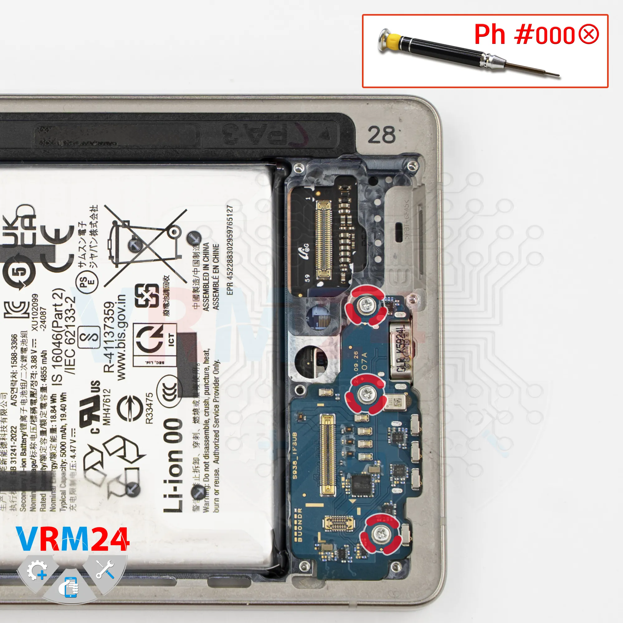
Now we move on to removing the sub-board.
First, we need to remove the three screws that secure the sub-board.
Carefully remove the screws.
It’s better to keep these screws separate from the previous ones, just in case, because the screws may differ in length.
Step 12.
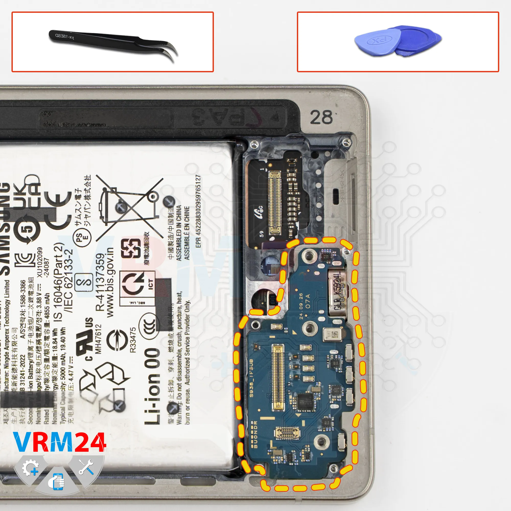
Remove the sub-board
After removing the screws, we take out the sub-board.
Carefully pry it up by the edge, lift it slightly - since the sub-board is slightly recessed - and remove it.
The sub-board contains the microphone, the charging port, and the card connector on the reverse side.
Step 13.
Unscrew the screws
Now we move to the upper section.
We need to remove the screws that secure not only the speaker, but also the motherboard.
Carefully remove the screws.
It’s also better to keep these screws separate from the previous ones.
Step 14.
Remove the earpiece speaker
After that, we need to disconnect the connector and remove the cover with the earpiece speaker.
Carefully pry it up at the correct spot and try to lift it.
Step 15.
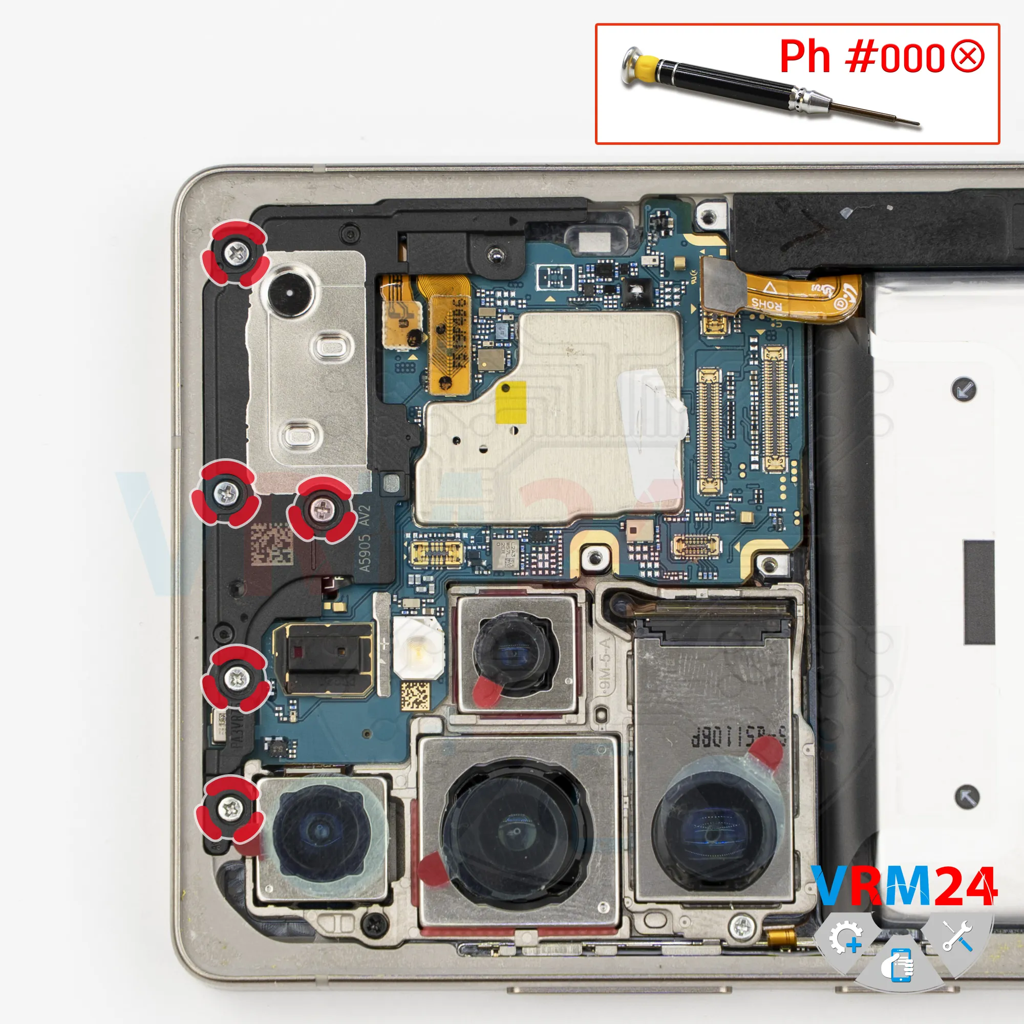
Unscrew the screws
We also need to remove the remaining screws.
These screws may differ from the previous ones, so they should also be kept separately.
Remove the screws that secure the cameras.
Step 16.
Disconnect the connectors
Carefully disconnect the connectors.
Step 17.
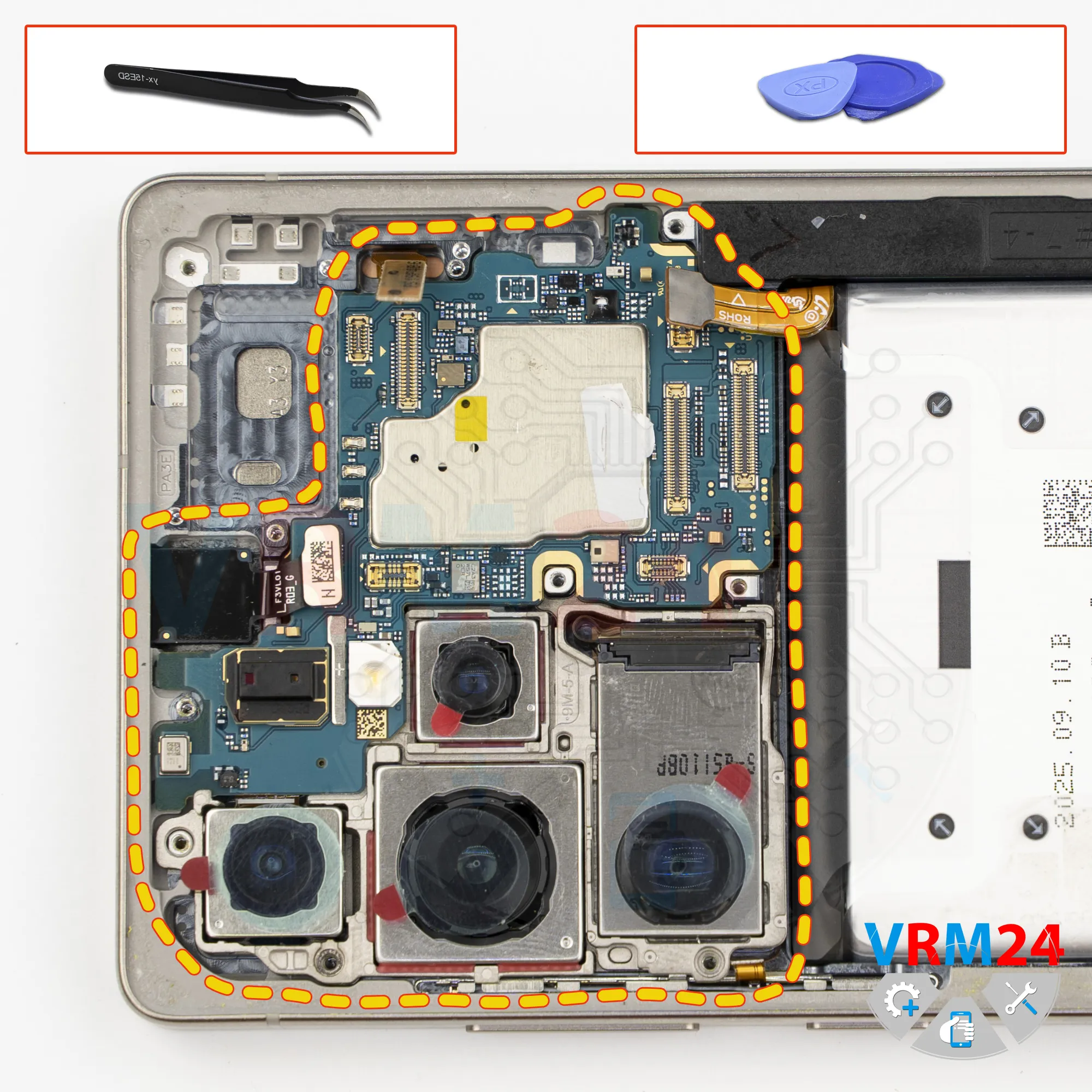
Remove the motherboard
Now we can remove the motherboard. Carefully pry it up by the edge, lift it, and remove it.
⚠️ Do not bend the circuit board when removing it or push tools under it. Unbeknownst to yourself, you can damage components or cables from the inside.
Step 18.
Remove the cameras
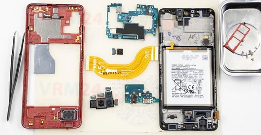
Flip the motherboard over - now we can disconnect the connectors and remove the rear camera assembly.
Disconnect the cameras and set them aside.
Step 19.
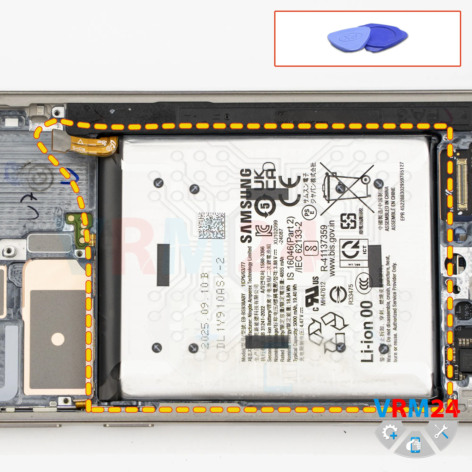
Remove the battery
Finally, we need to remove the battery.
(in our case) We simply pull it slightly, and it detaches. Very often, on Samsung devices, the battery does not come off this easily.
Step 20.
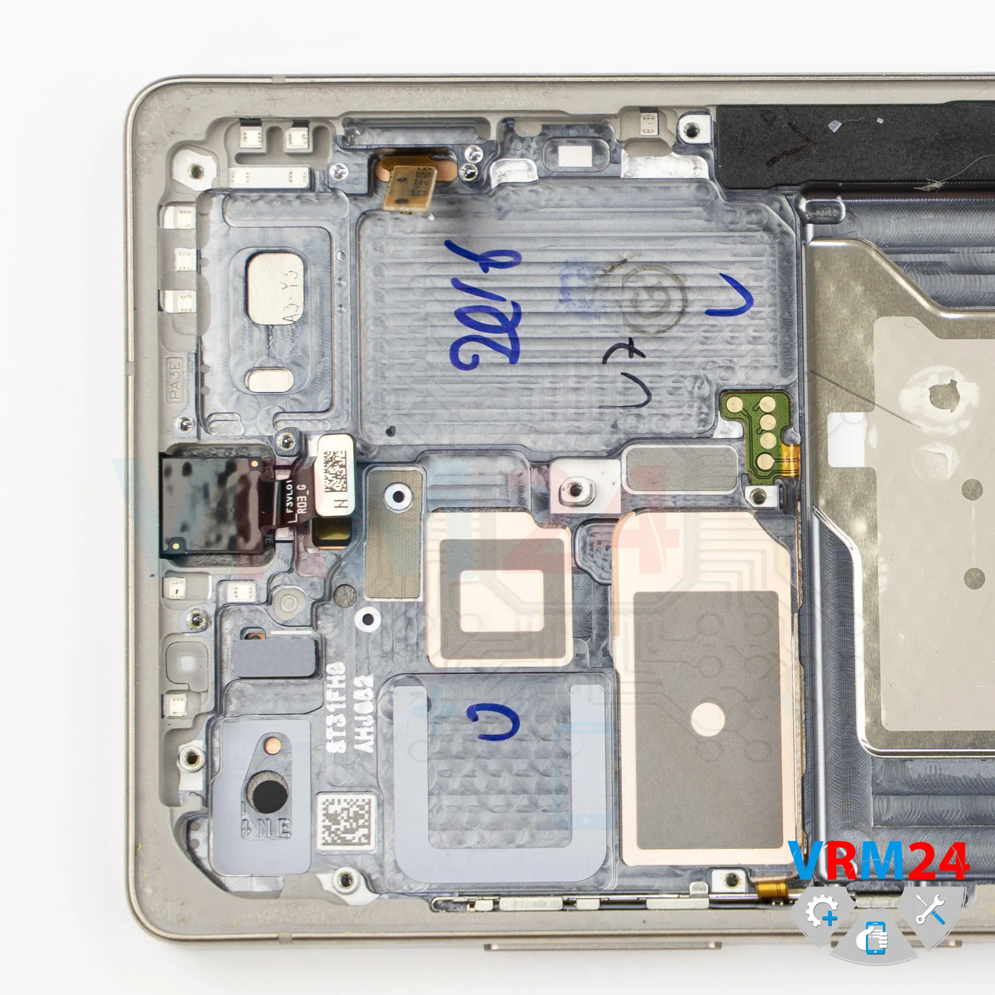
In the display frame remained
ℹ️ In the housing remained: the front camera.

If you have a question, ask us, and we will try to answer in as much detail as possible. If this article was helpful for you, please rate it.

4873
Views
4
Likes
—
Share
0
Questions
Related Instructions
Related Reviews
Related Blog
Top instructions
Check our
Top Samsung instructions most liked by readers
New instructions
Check our
New Samsung brand instructions on vrm24.com