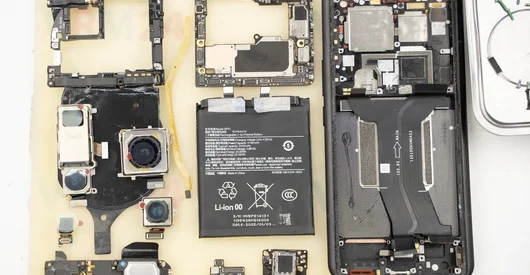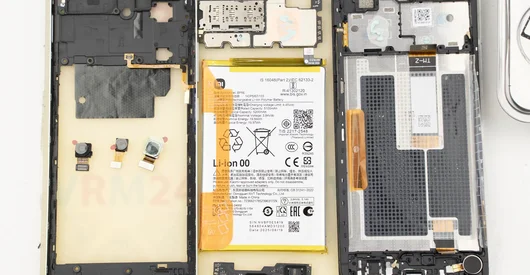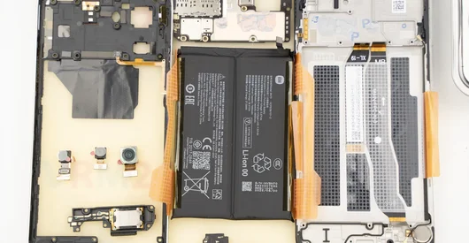
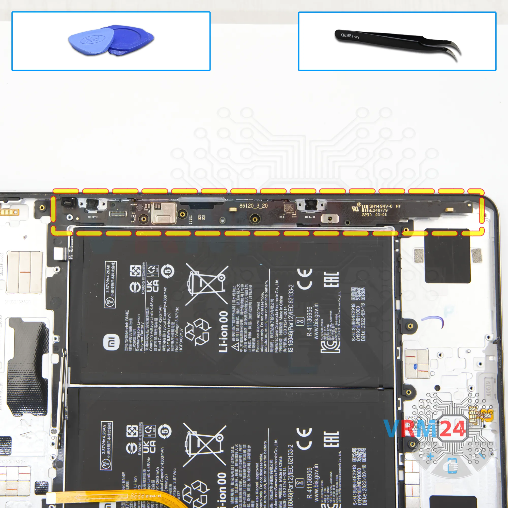
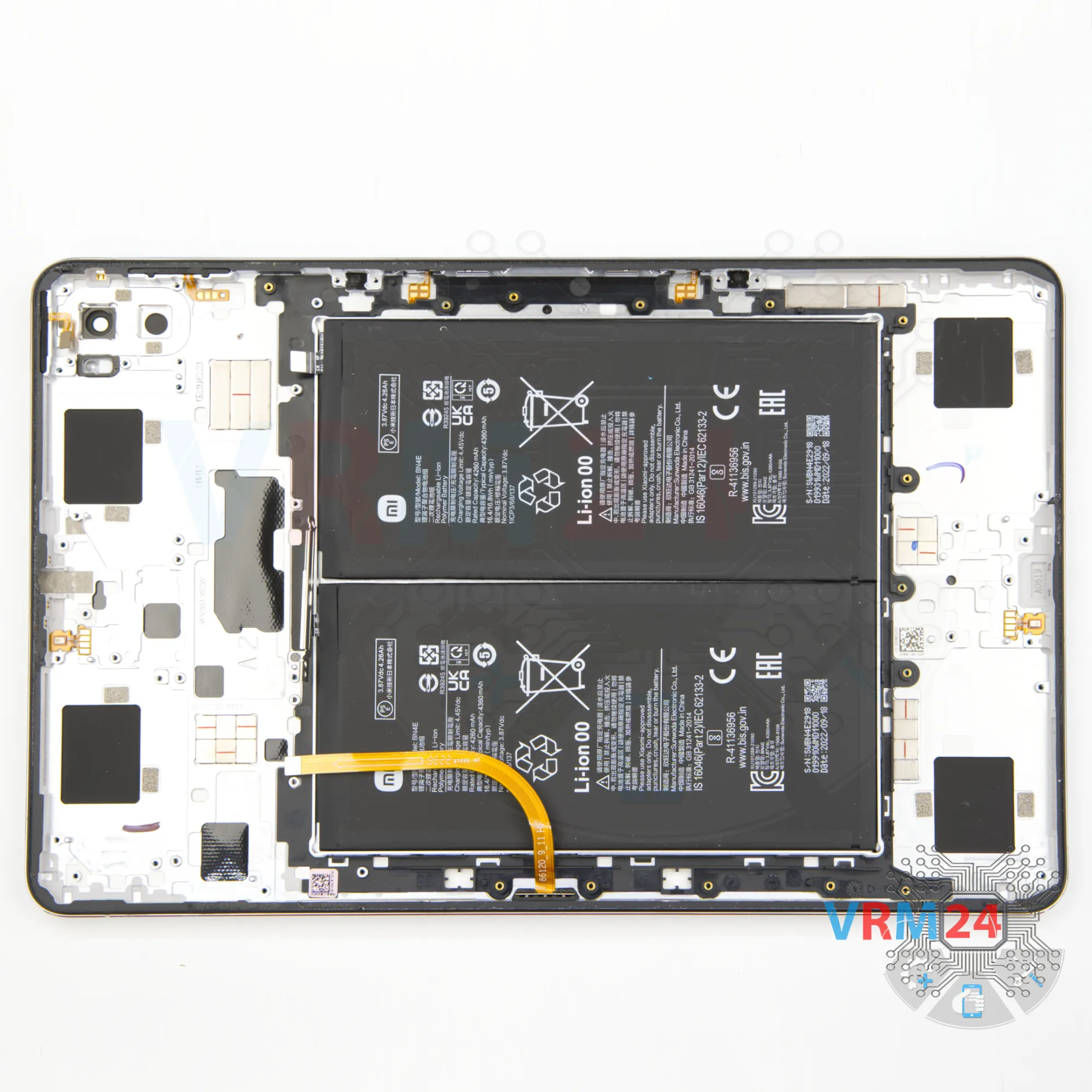
Recommended tools
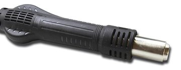
Heat gun
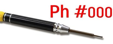
Screwdriver Phillips #000
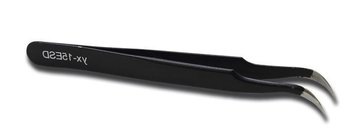
Tweezers
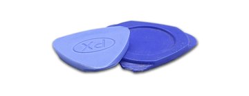
Non-metallic tool
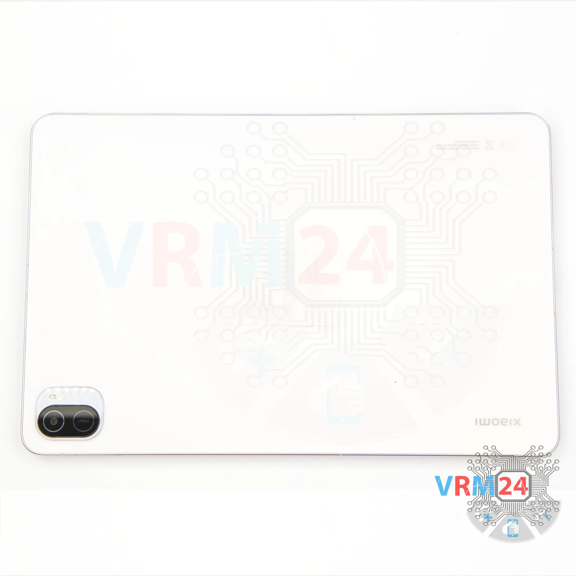
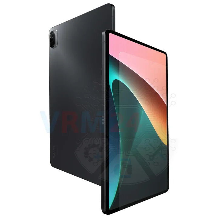
Disassembly/Repair of the mobile device Xiaomi Pad 5 (Xiaomi Pad 5 21051182G) with each step description and the required set of tools.
10483
Views
2
Likes
—
Share
0
Questions

Step 1.
Before disassembling!
⚠️ Before disassembling, do not forget to turn your phone off.
Step 2.
Open the display module
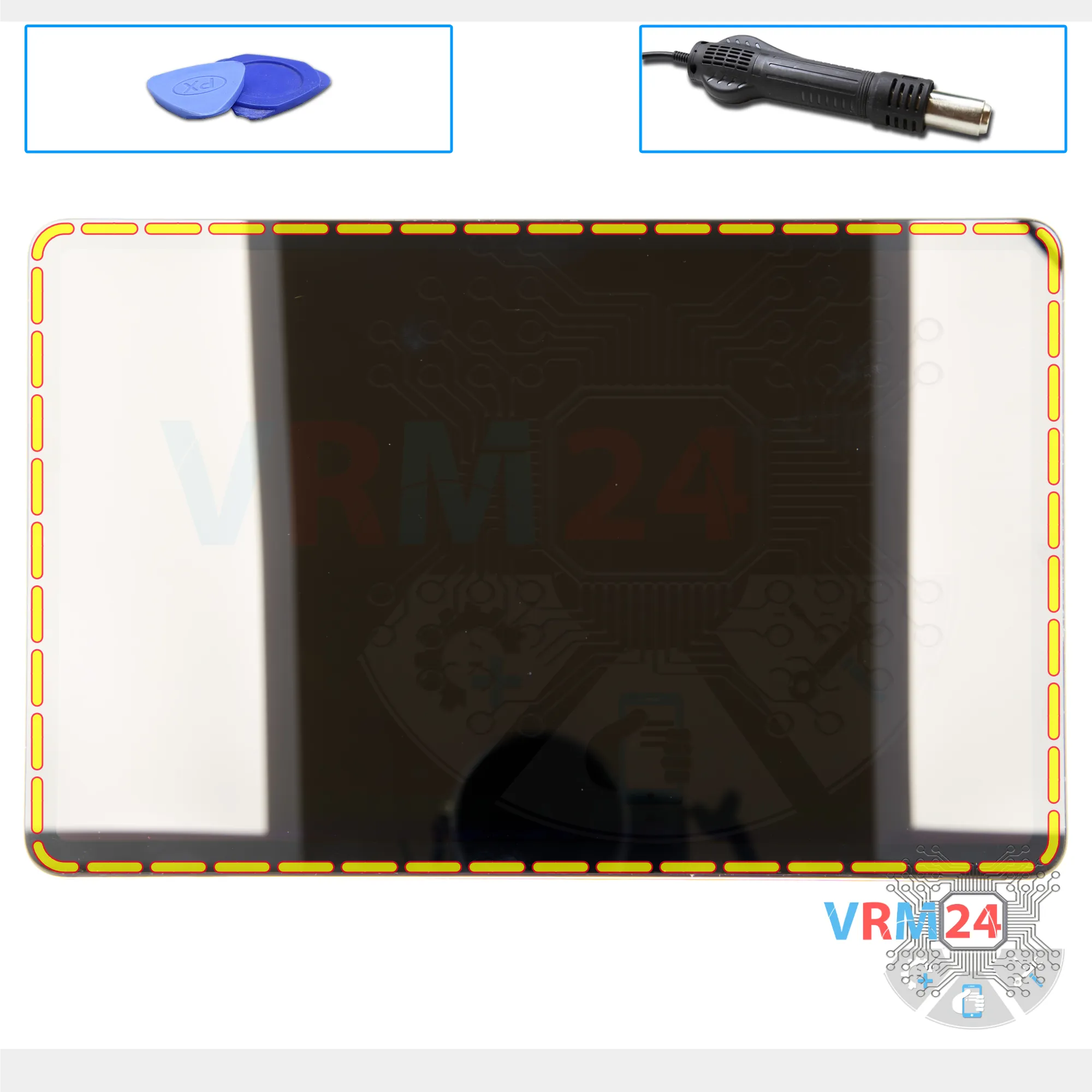
First of all we need to heat the surface of the display to a temperature of about 70° C or 160° F. For this we use a heating mat.
⚠️ We highly recommend not to detach the display at home as there is a high probability of damaging it.
So, after heating the display, after about ten minutes, we can proceed to detach the display. Carefully insert a thin plastic film into the gap between the display and the housing. This film could be from a new display or from a stationery store.
We carefully run it along the edge of the display to detach it.
⚠️ We always need to be careful not to run the tool deep inside, because in some places there may be cables to the display or touchscreen.
Step 3.
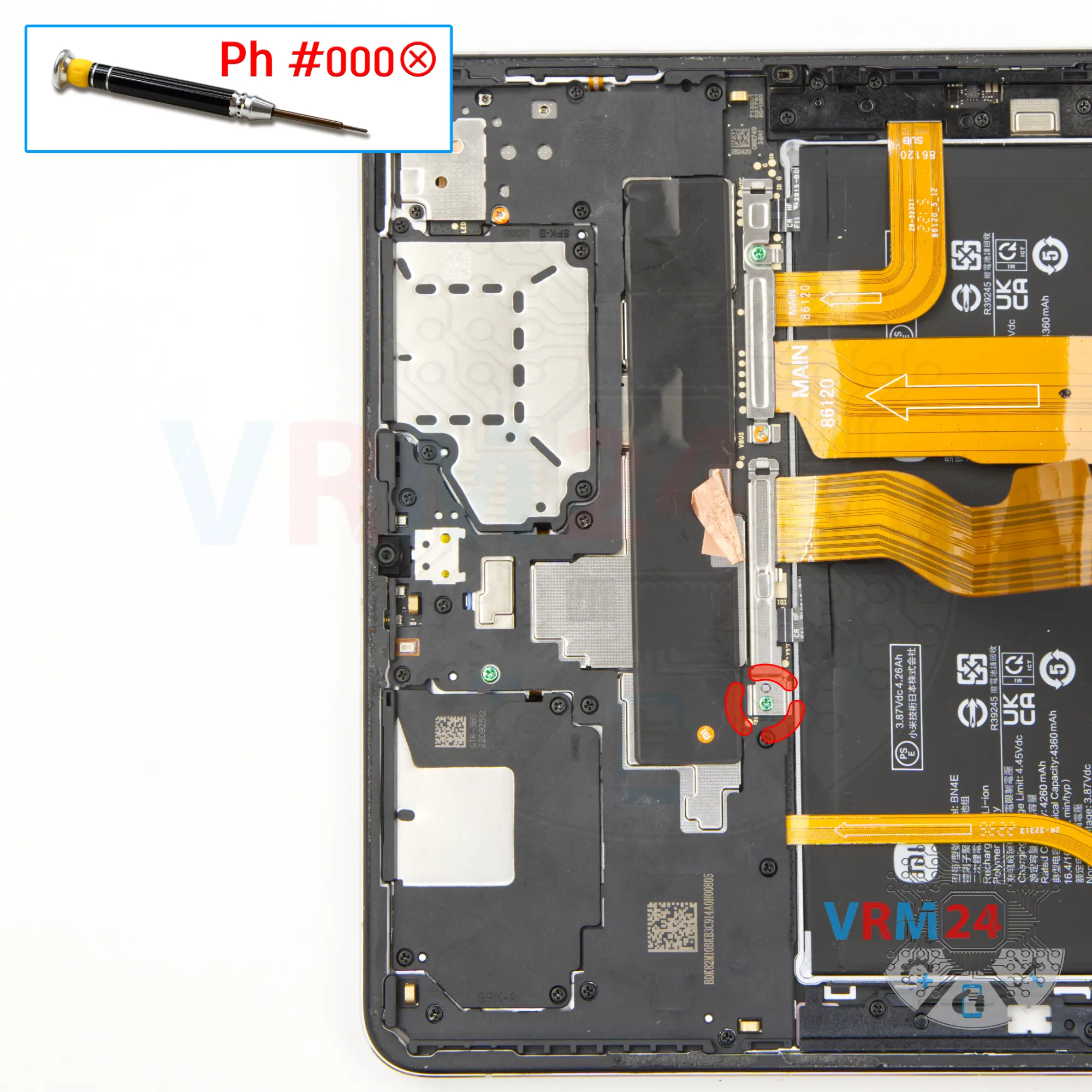
Unscrew one screw
Then we unscrew one screw using a Phillips screwdriver 1.5 mm or #000.
Step 4.
Disconnect the battery connector
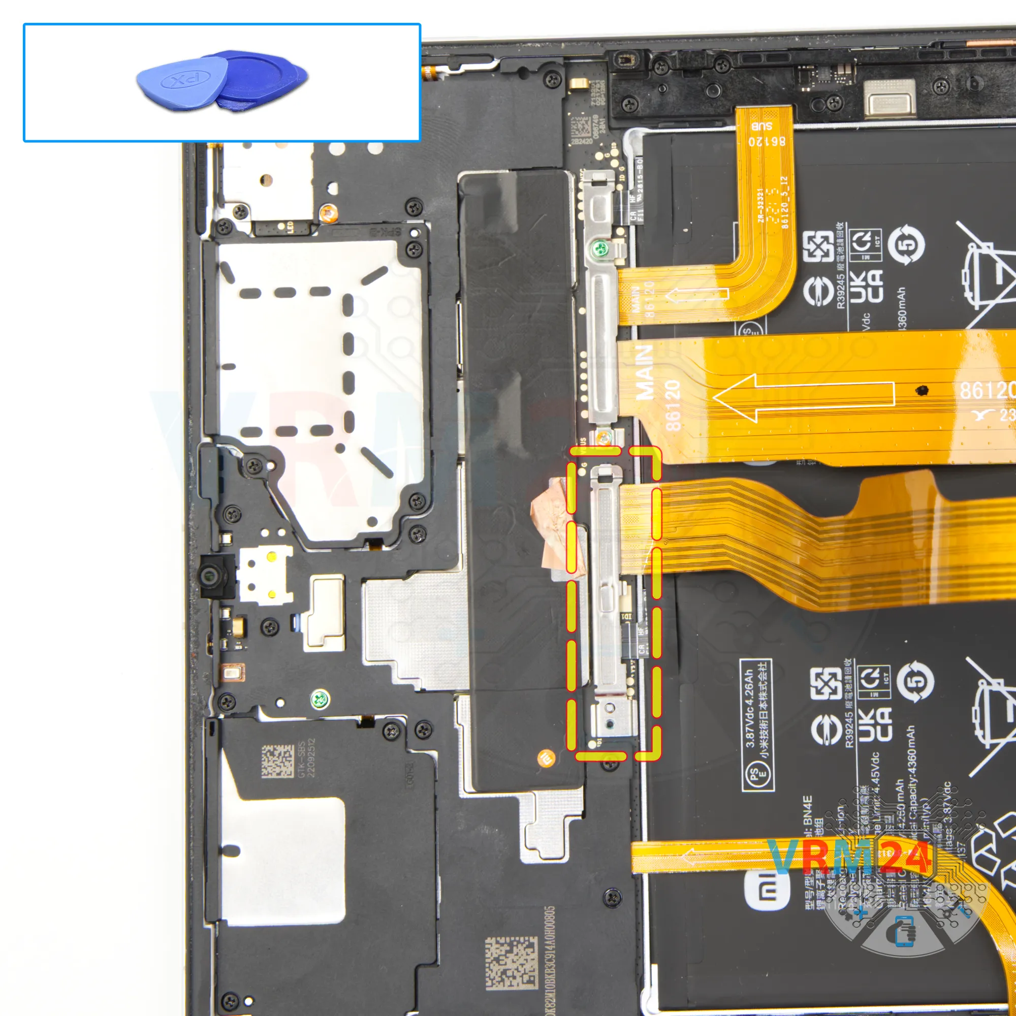
We carefully remove the bracket that hides connectors.
After that we disconnect the battery connector.
ℹ️ The Xiaomi Pad 5 21051182G model has a battery BN4E with a capacity of 4260 mAh (also known as a rechargeable battery).
And we also disconnect the connector to the display and then we can remove the display.
Step 5.
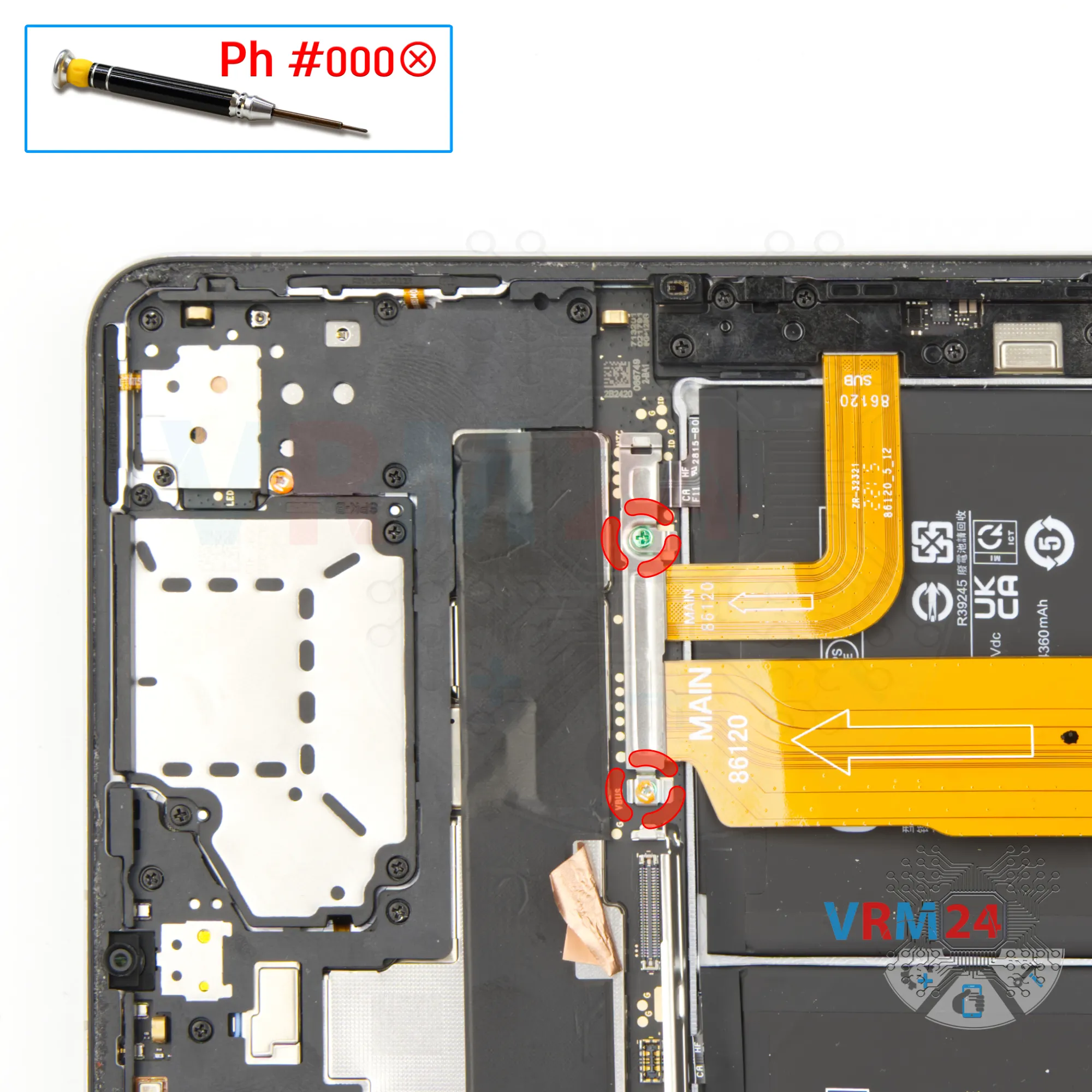
Unscrew the screws
We unscrew the two screws with a Phillips screwdriver 1.5 mm or #000.
Step 6.
Unscrew the screws
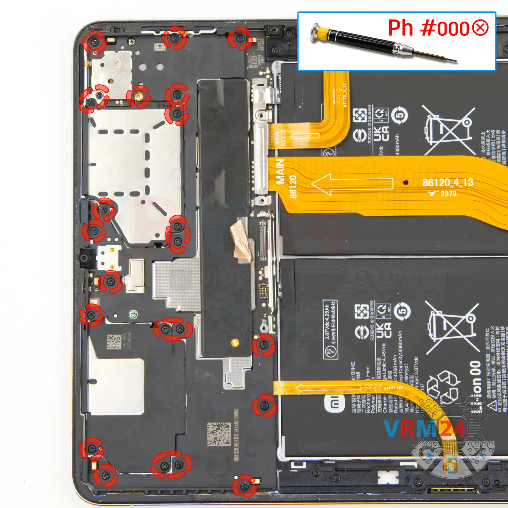
Using a screwdriver Phillips 1.5 mm (PH #000), unscrew the twenty three small black screws.
Step 7.
Unscrew one screw
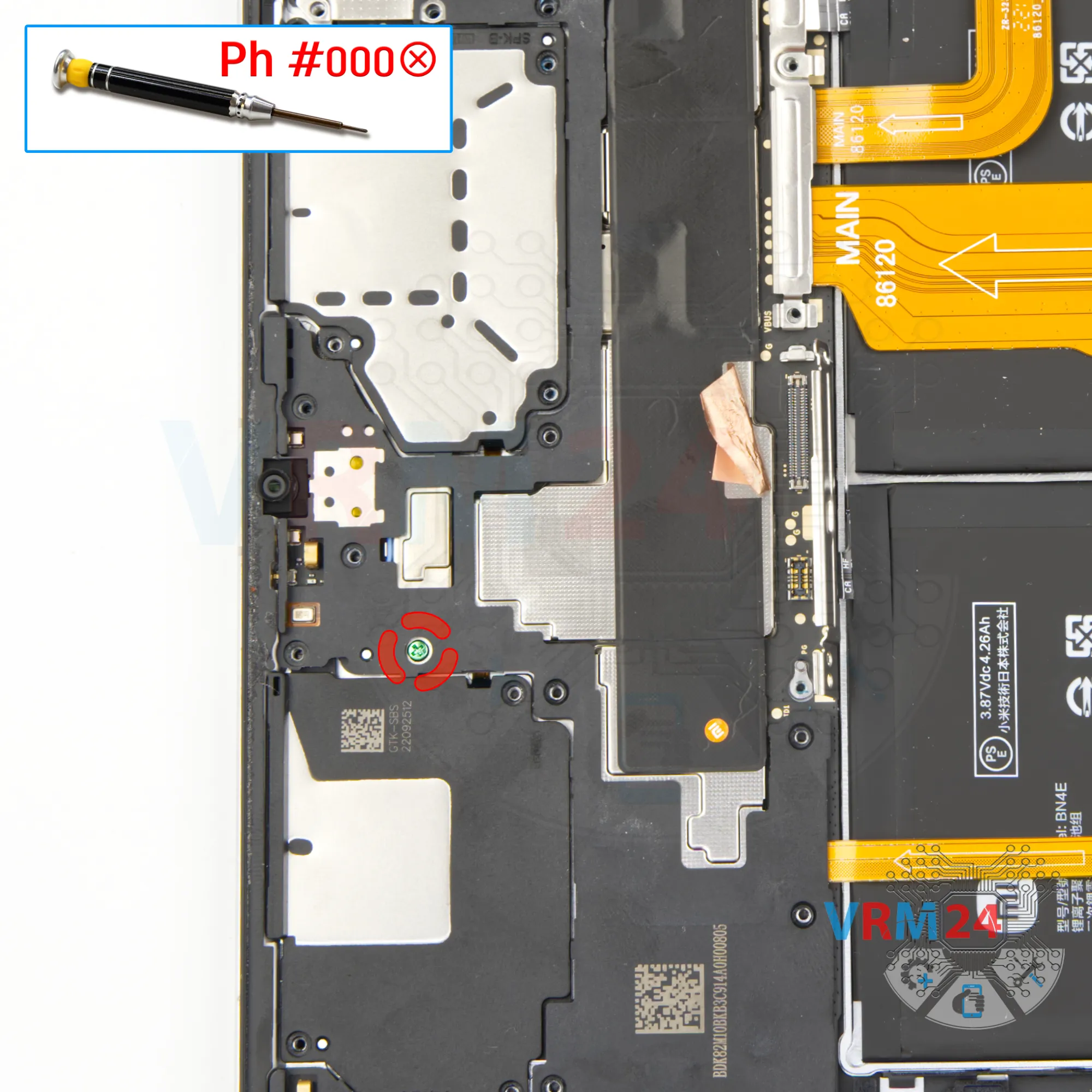
Using a screwdriver Phillips 1.5 mm (PH #000), unscrew the one small copper green (color) screw.
Step 8.
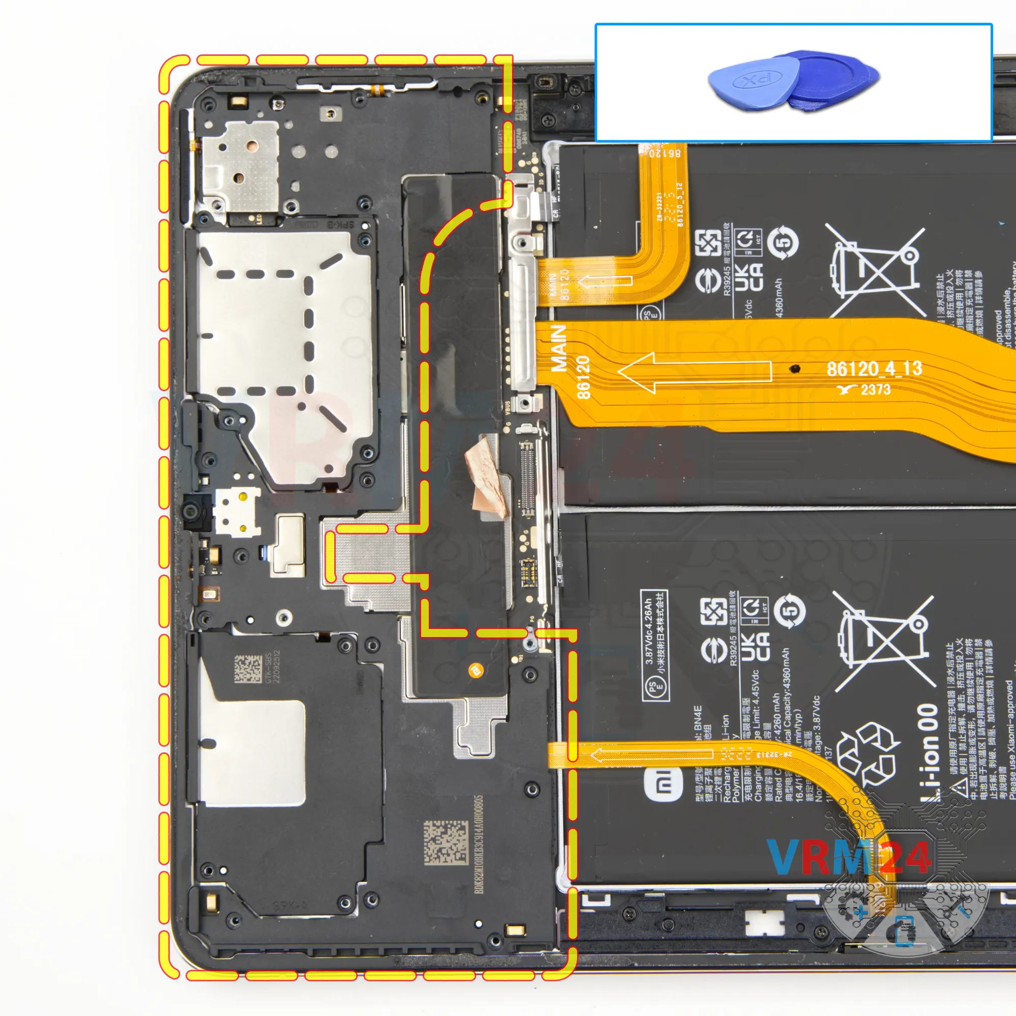
Open the cover
And we can detach the cover hiding the motherboard.
Step 9.
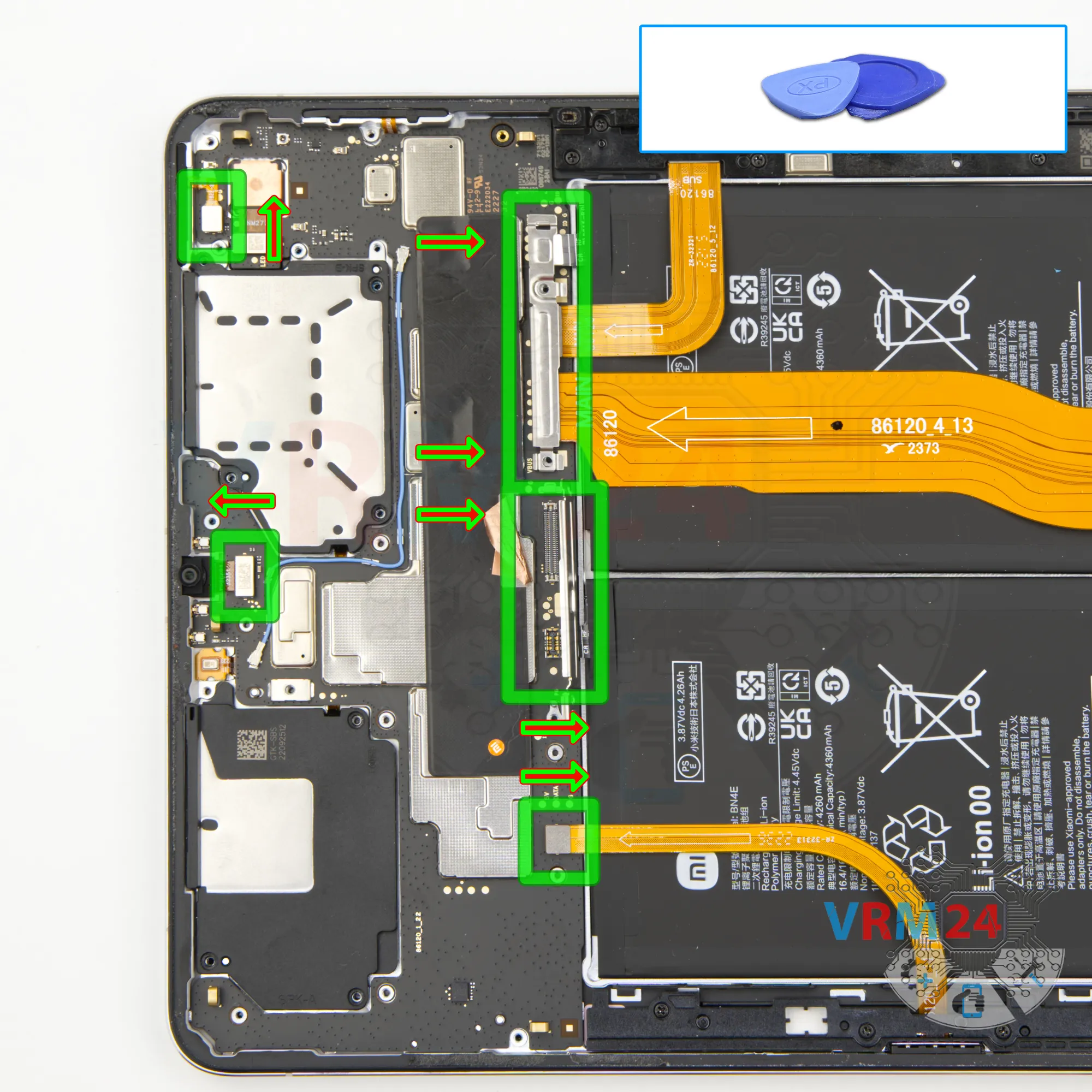
Disconnect the connectors
We disconnect the second battery connector.
ℹ️ The Xiaomi Pad 5 21051182G model has a battery BN4E with a capacity of 4260 mAh (also known as a rechargeable battery).
We also disconnect the connectors of the sensor, front camera, sub-board and inter-board cables.
Step 10.
Remove the motherboard
We move on to detach the motherboard.
Carefully pry at the edge, lift the motherboard and remove it.
Step 11.
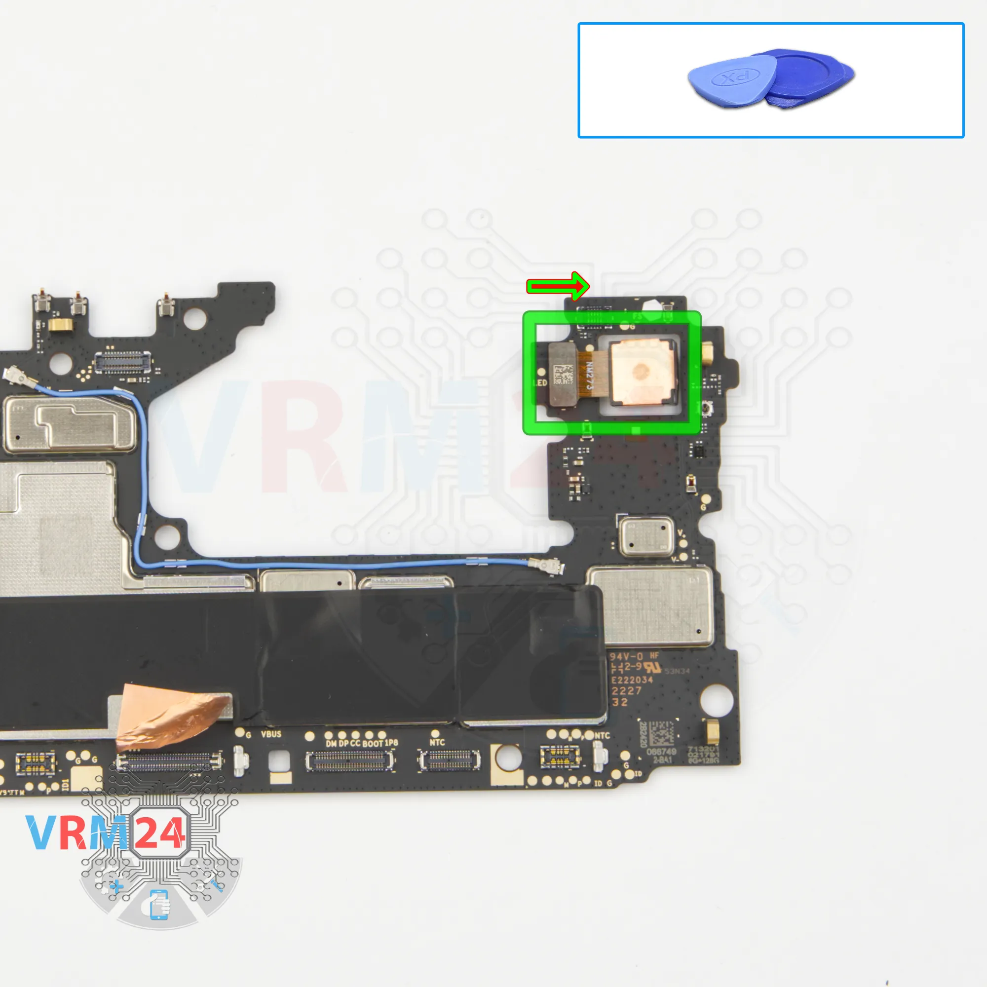
Remove the rear camera
And we can detach the main camera. Gently hold the camera, disconnect the connector and remove the main camera.
Step 12.
Unscrew the screws
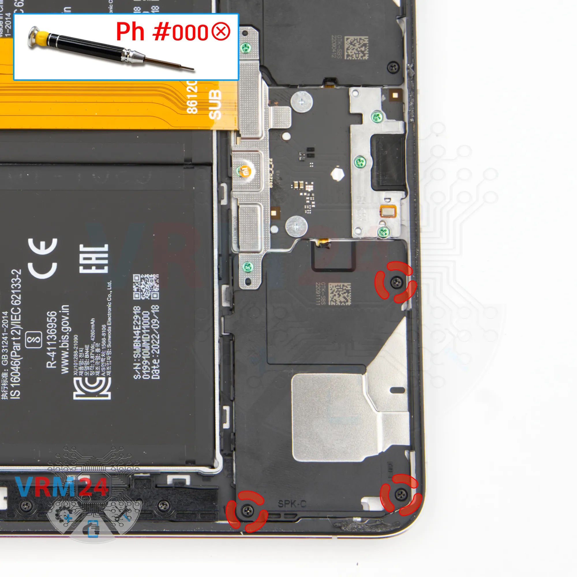
Using a screwdriver Phillips 1.5 mm (PH #000), unscrew the three screws securing the loudspeaker.
Step 13.
Unscrew the screws
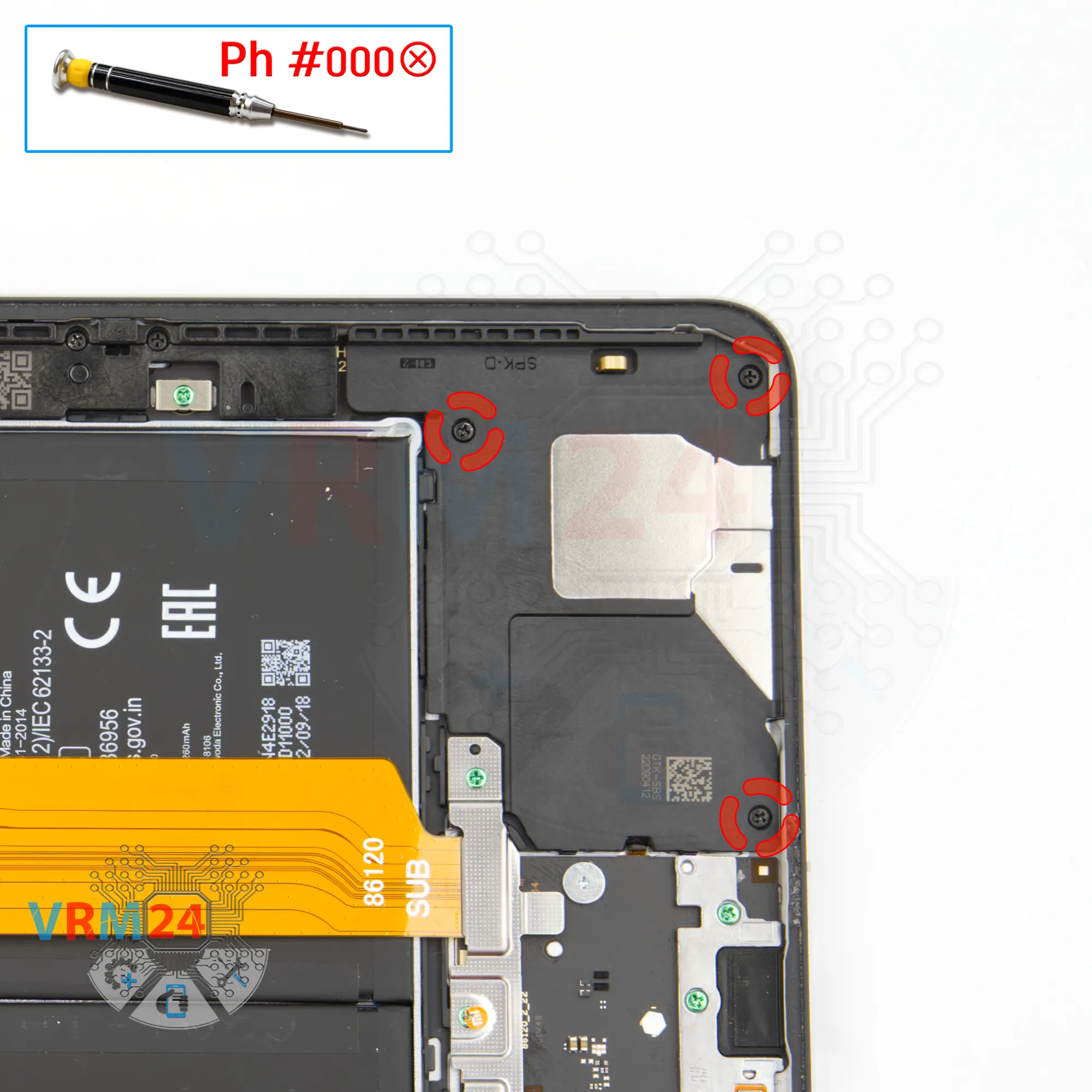
Using a screwdriver Phillips 1.5 mm (PH #000), unscrew the three screws securing the second loudspeaker.
Step 14.
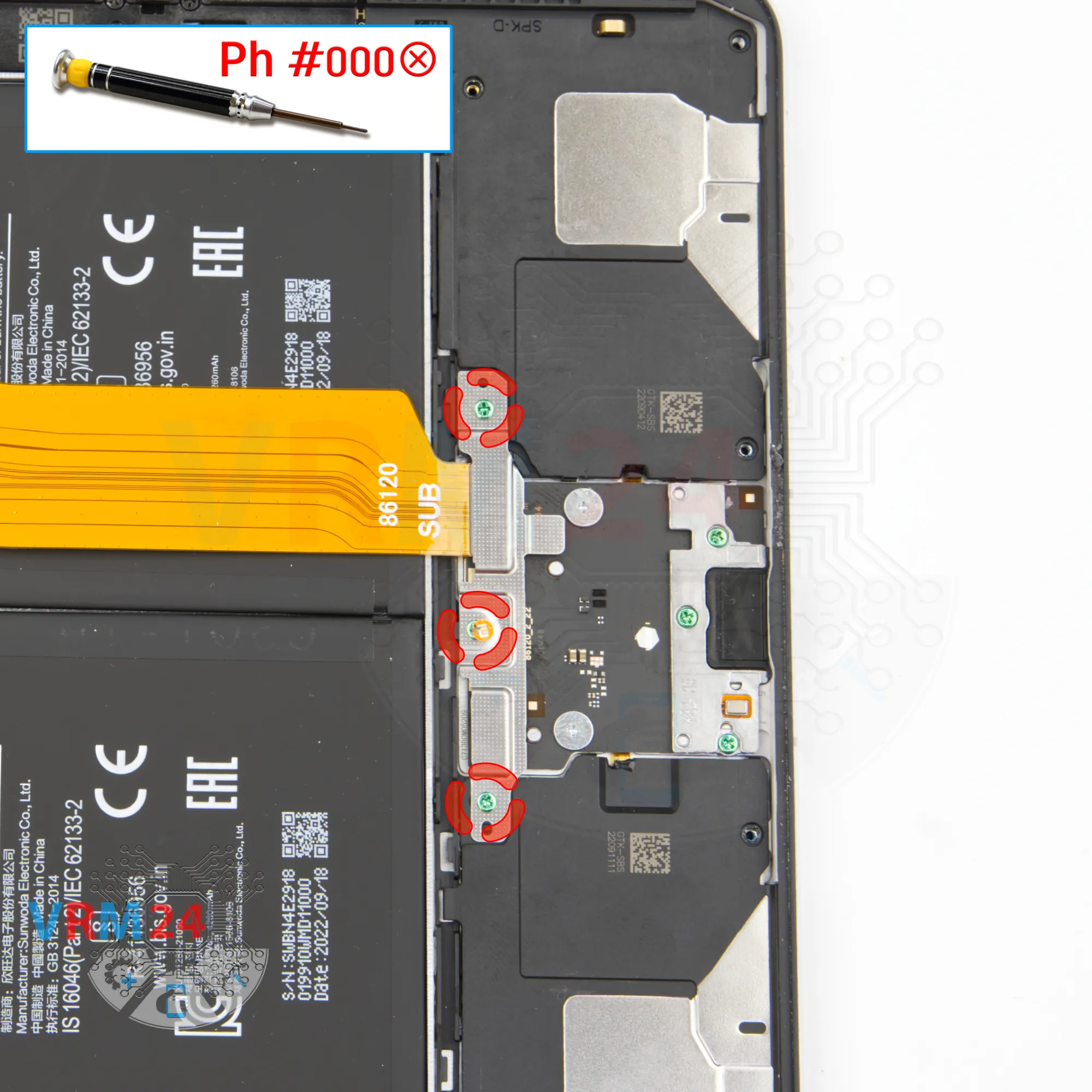
Unscrew the screws
Using a screwdriver Phillips 1.5 mm (PH #000), unscrew the three screws securing the bracket.
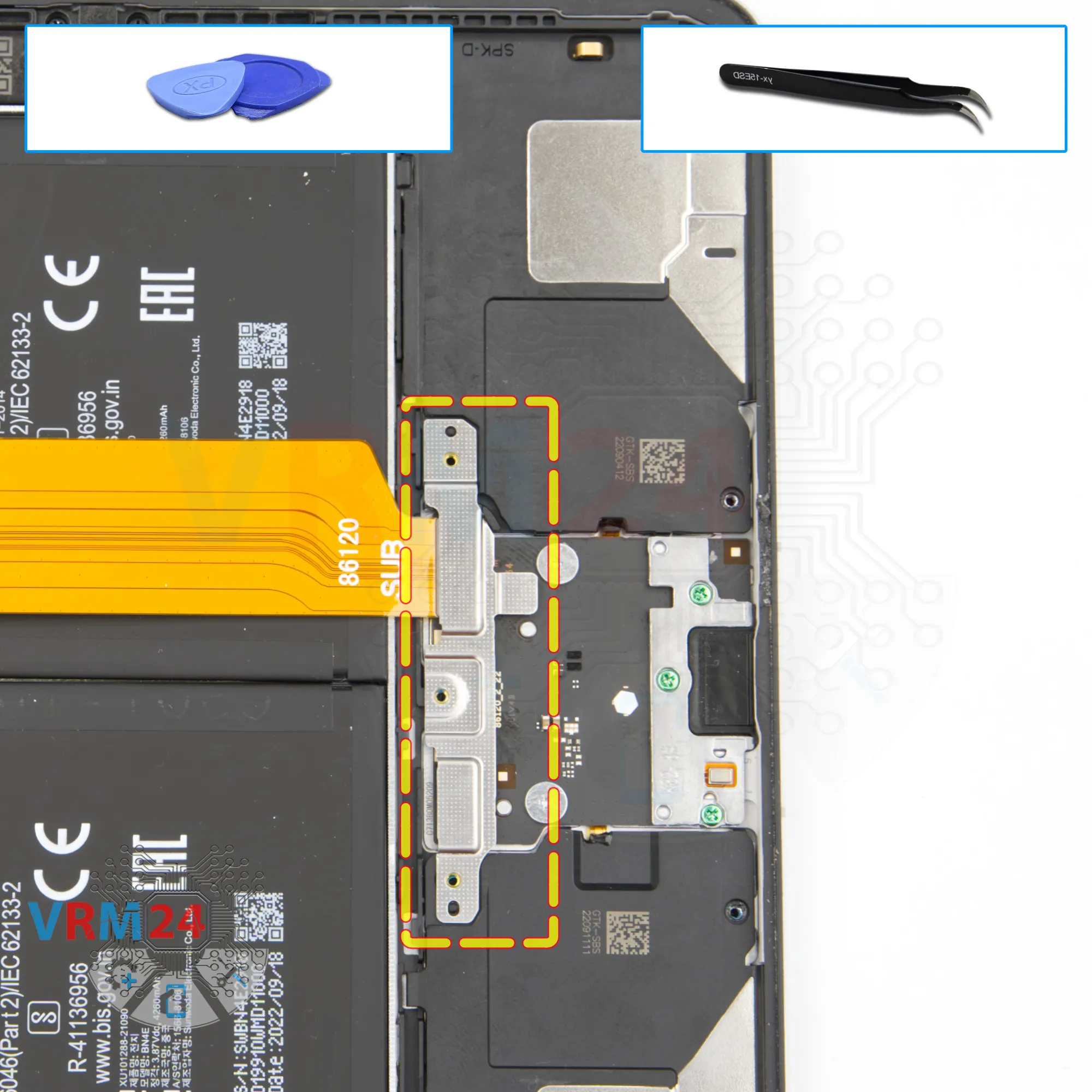
Step 15.
Remove the bracket
We remove the bracket that holds the inter-board cable connector.
Step 16.
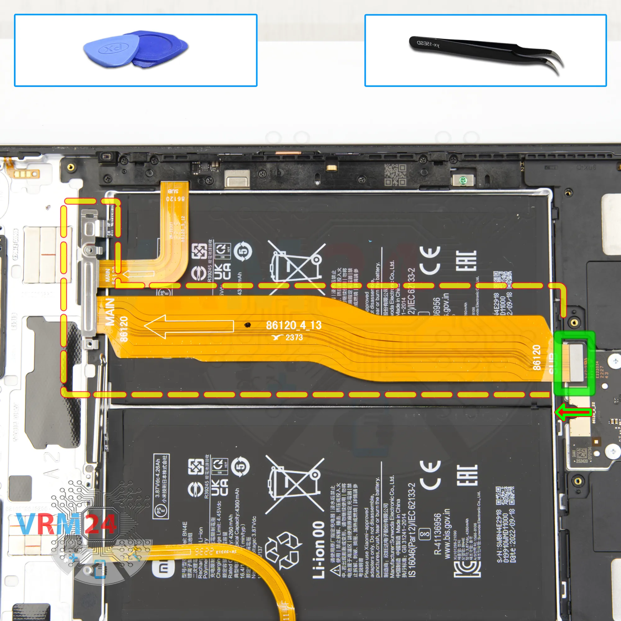
Remove the interconnect cable
We disconnect the connector and remove the inter-board flex.
Step 17.
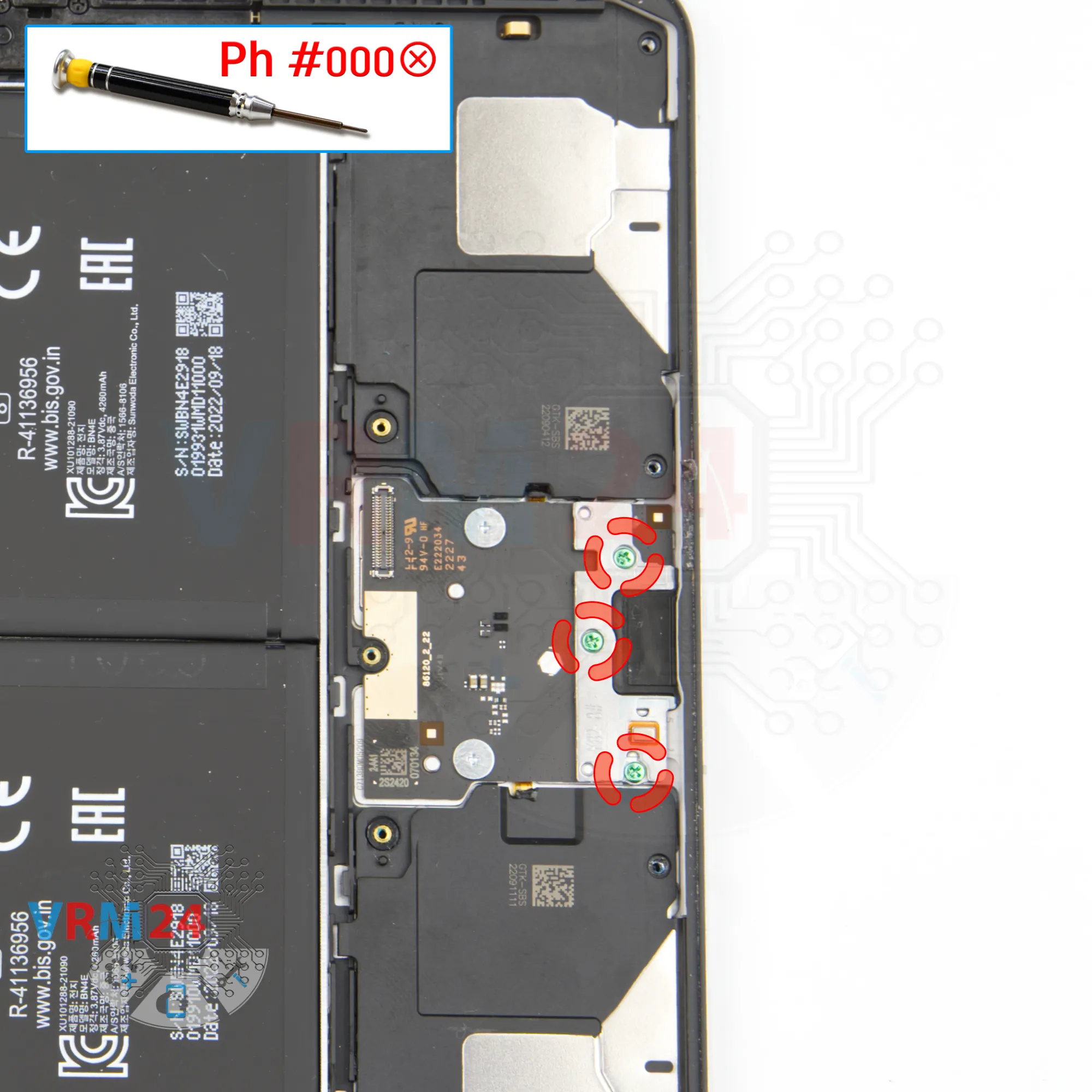
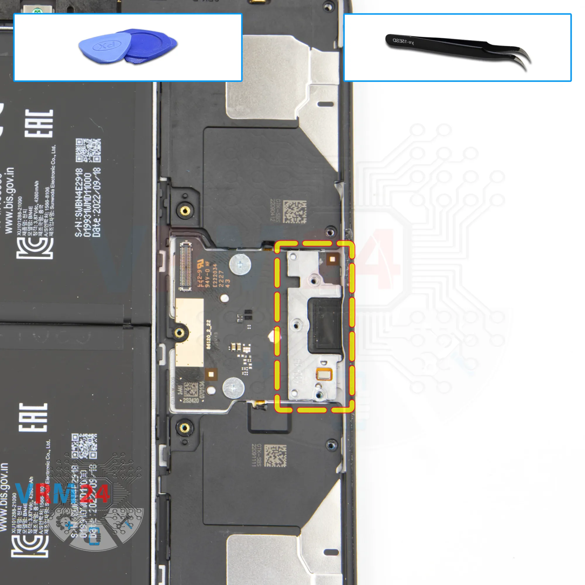
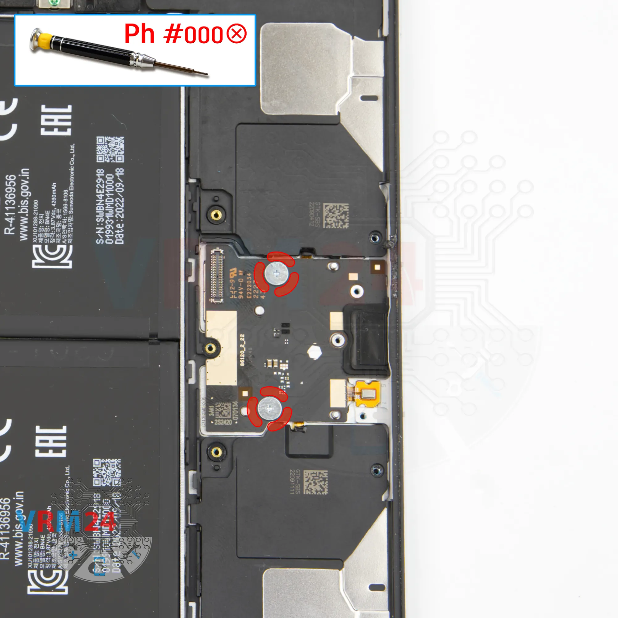
Unscrew the screws
Using a screwdriver Phillips 1.5 mm (PH #000), unscrew the three screws securing the charging port.
Step 18.
Remove the bracket
We carefully remove the bracket holding the charging port and microphone.
Step 19.
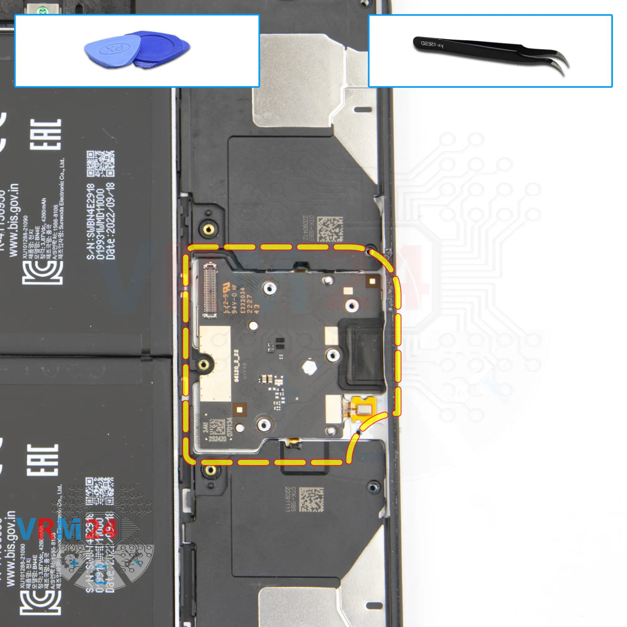
Unscrew the screws
Using a screwdriver Phillips 1.5 mm (PH #000), unscrew the two screws securing the sub-board.
Step 20.
Remove the sub-board
And we gently pry up the edge and remove the sub-board with the charging port, but the microphone remains in the housing.
Step 21.
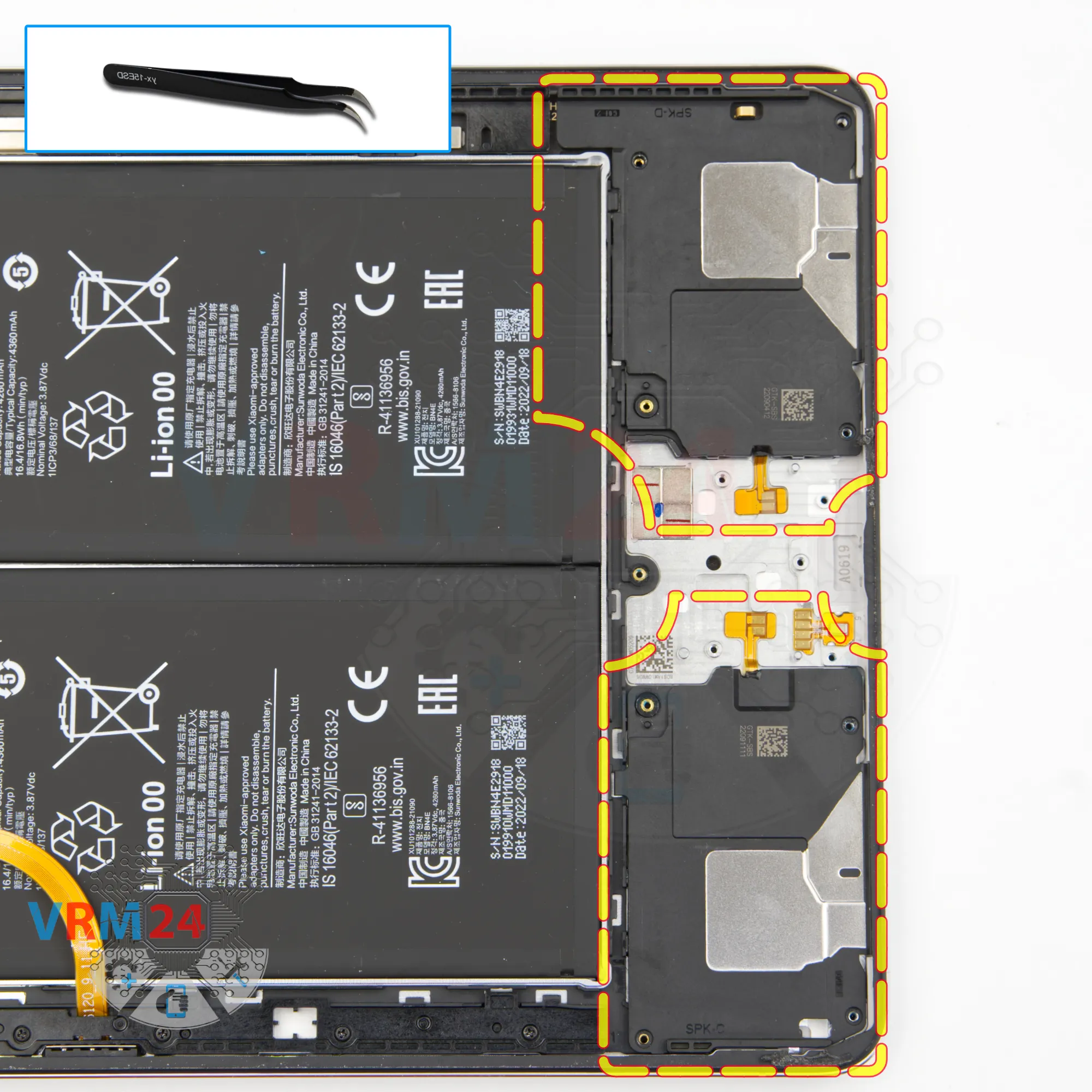
Remove the loudspeaker
And we need to detach the loudspeakers.
We also hook the speaker on the side, the far side from the contact pad and lift and detach the loudspeaker.
Step 22.
Unscrew the screws
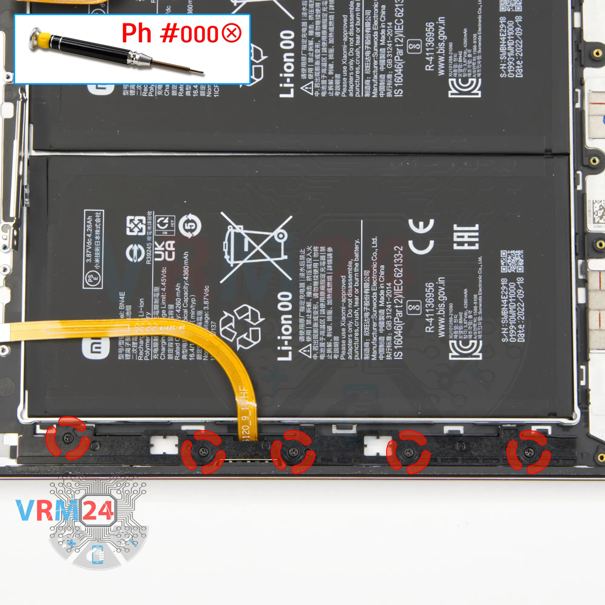
Using a screwdriver Phillips 1.5 mm (PH #000), unscrew the five screws on the side.
Step 23.
Open the cover
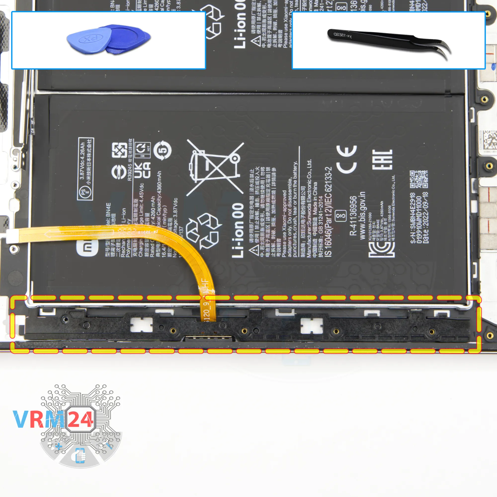
Carefully remove the cover on the side that holds the keyboard connector.
Step 24.
Unscrew the screws
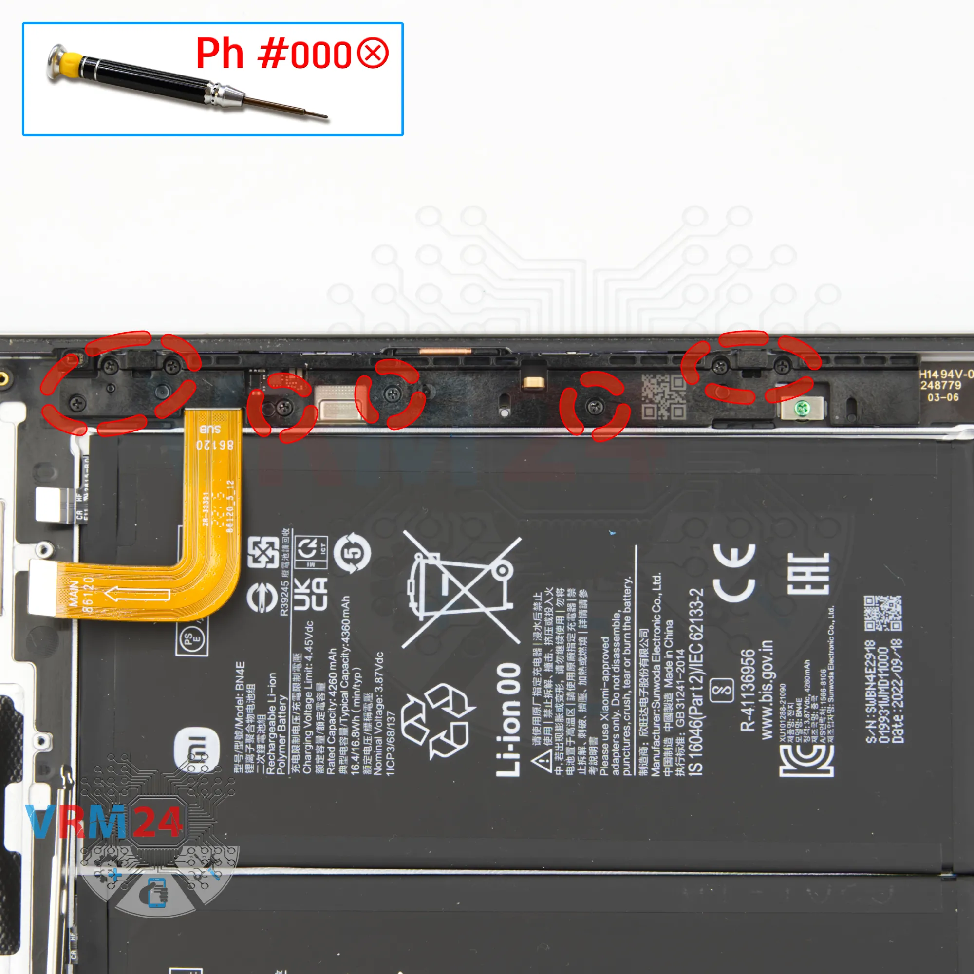
Using a screwdriver Phillips 1.5 mm (PH #000), unscrew the eight screws on the other side.
Step 25.
Open the cover
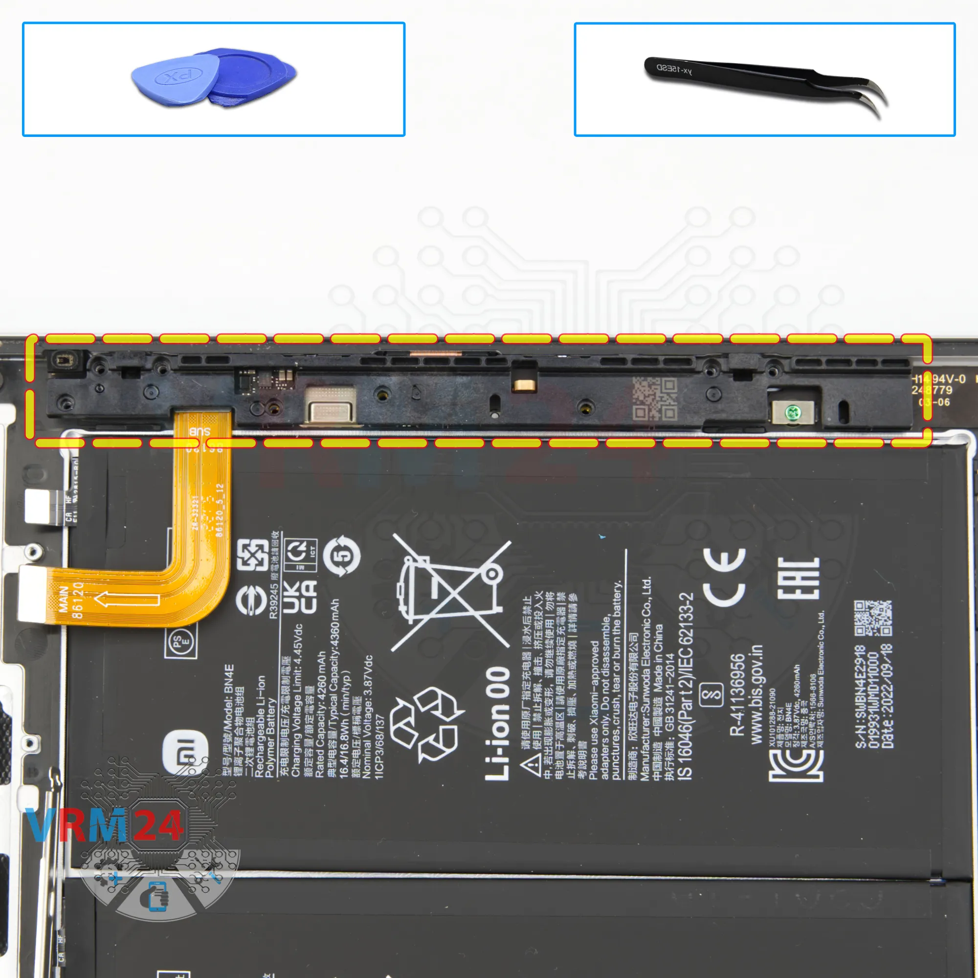
And we can remove the cover that hides long narrow board.
Step 26.
Remove the loudspeaker
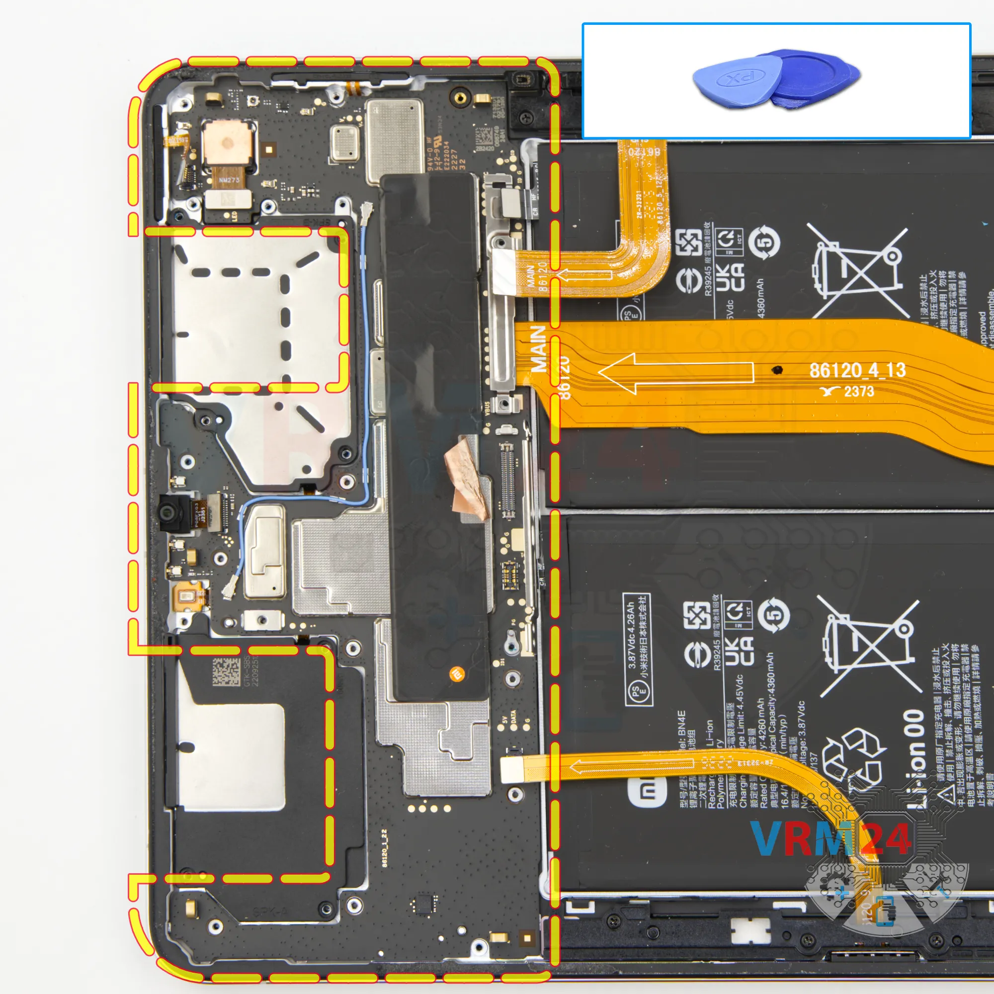
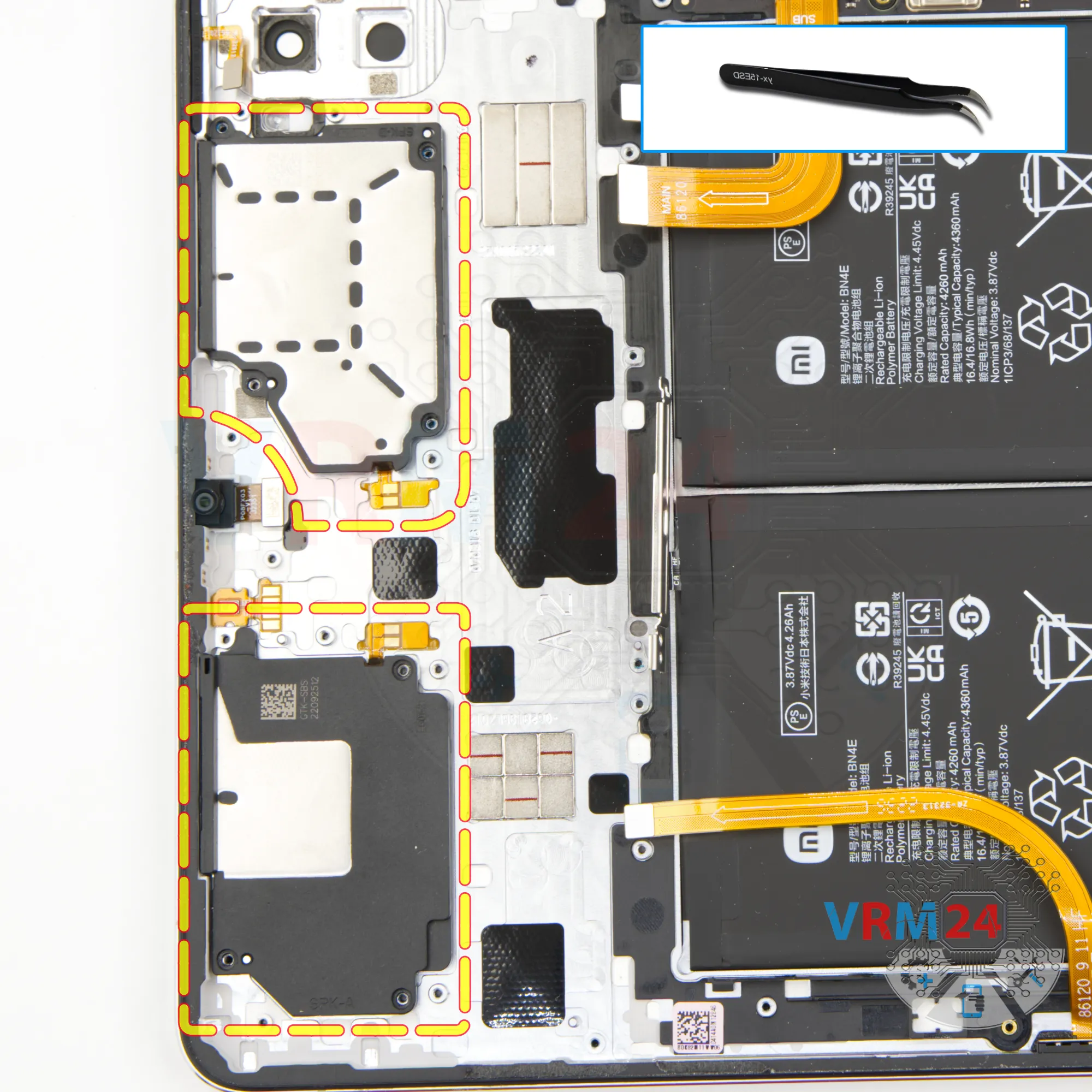
And we need to detach the third and fourth loudspeakers.
We pry the speaker on the side, the far side from the contact pad and lift and detach the loudspeaker.
Step 27.
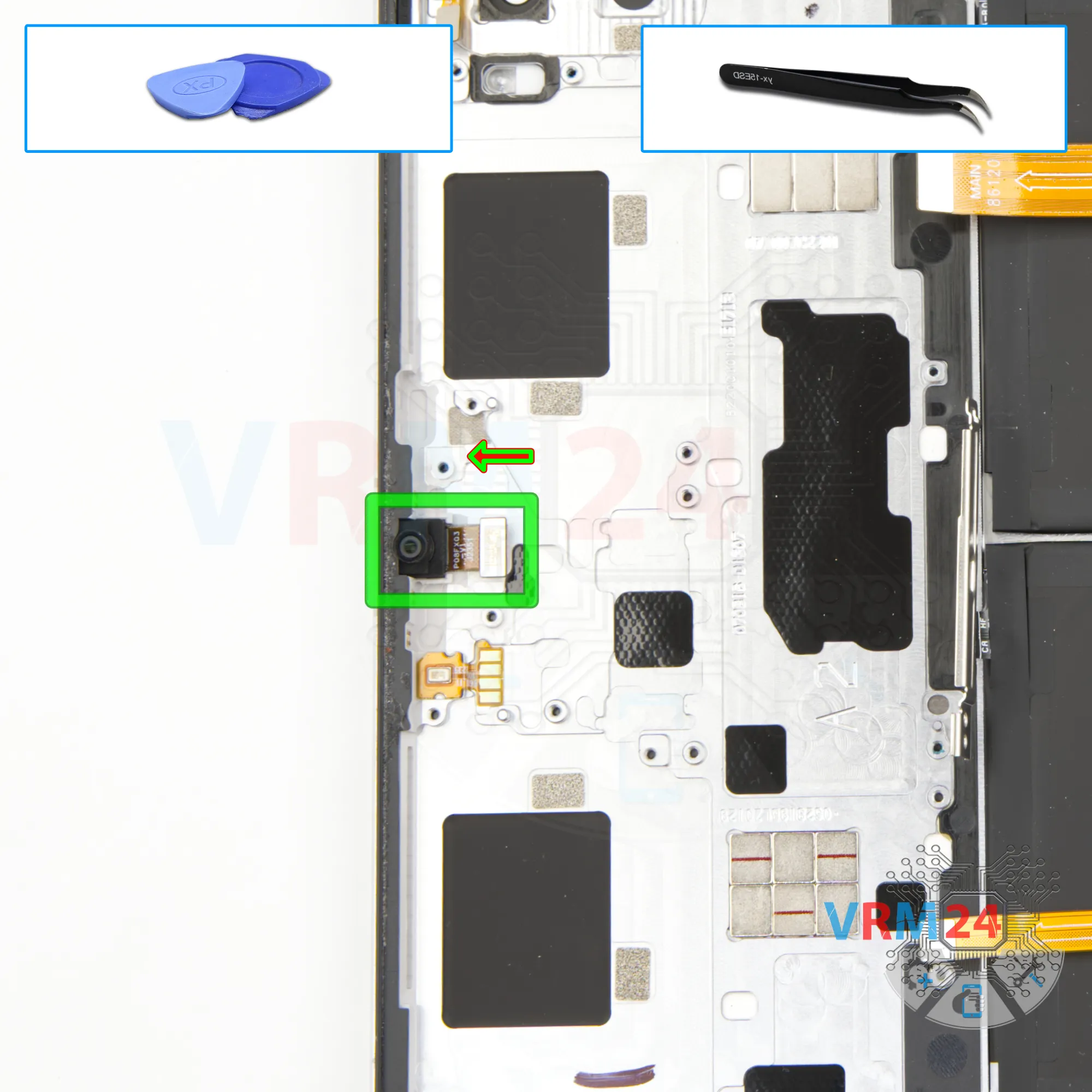
Remove the front camera
We can remove the front camera. The camera is taped a little to the housing so be careful.
Step 28.
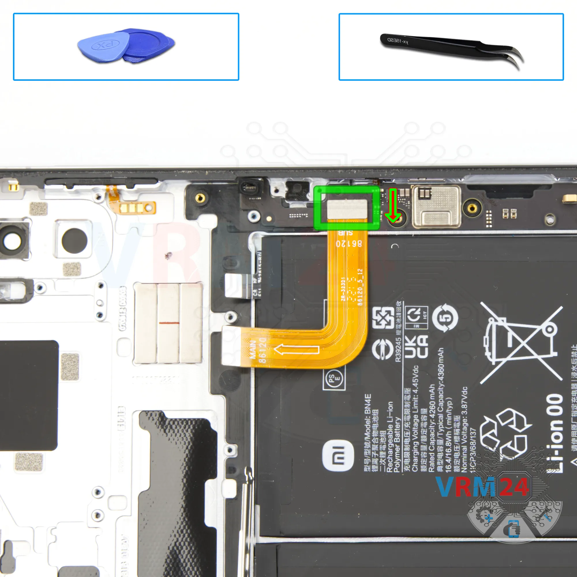
Remove the interconnect cable
We disconnect the connector and remove the inter-board flex.
Step 29.
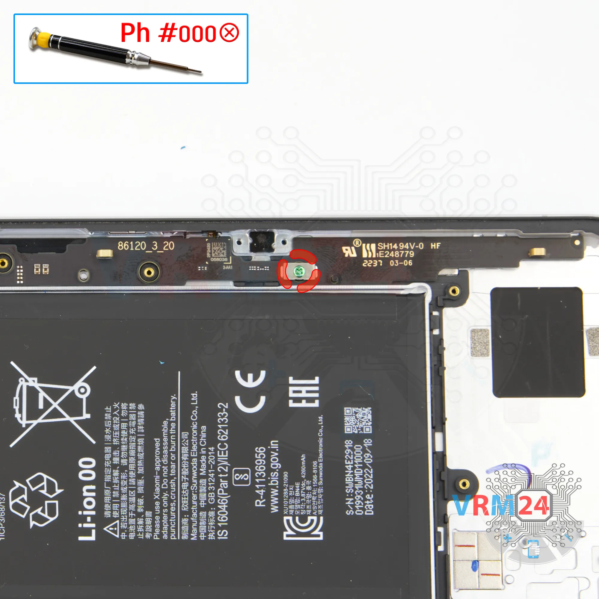
Unscrew one screw
We use the same 1.5mm Phillips screwdriver to unscrew one screws that holds the long narrow board.
Step 30.
Remove the sub-board
We can try to remove the circuit board. Carefully lift it and take it out.
⚠️ Be careful because the printed circuit board is slightly taped to the housing on one side.
⚠️ Do not force it or try to bend the board to remove it.
Step 31.
In the housing remained
In the housing remained: battery.

If you have a question, ask us, and we will try to answer in as much detail as possible. If this article was helpful for you, please rate it.

10483
Views
2
Likes
—
Share
0
Questions
Related Instructions
Related Reviews
Related Blog
Top instructions
Check our
Top Xiaomi instructions most liked by readers
New instructions
Check our
New Xiaomi brand instructions on vrm24.com