

Recommended tools
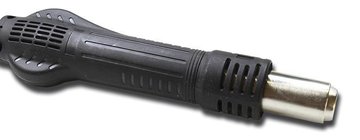
Heat gun
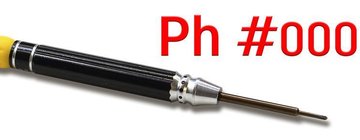
Screwdriver Phillips #000
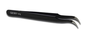
Tweezers
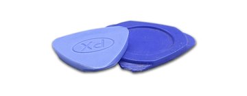
Non-metallic tool
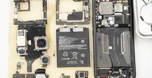
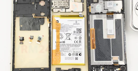
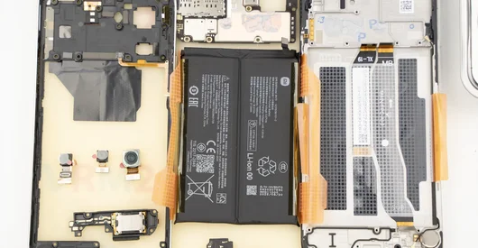
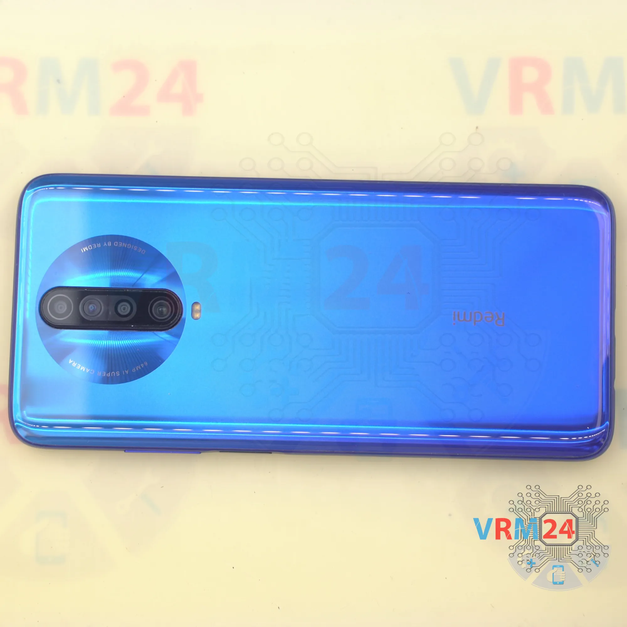
Disassembly/Repair of the mobile device Xiaomi RedMi K30 (Xiaomi RedMi K30 M1912G7BC) with each step description and the required set of tools.
3999
Views
1
Likes
—
Share
0
Questions

Step 1.
Before disassembling!
⚠️ Before disassembling, do not forget to turn your phone off.
Step 2.
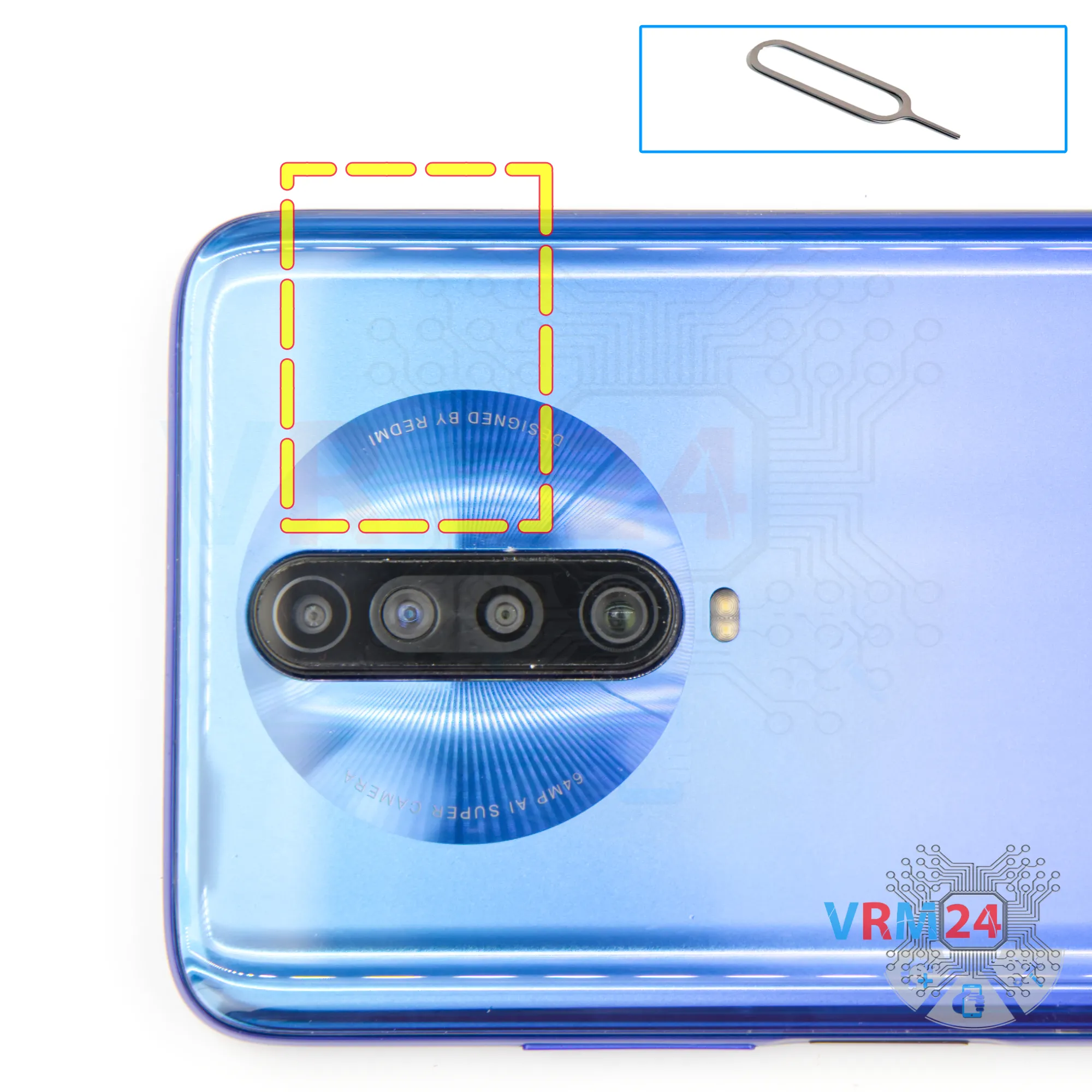
Remove the tray
At the very beginning we need to remove the card tray for this we use a special tool, insert it into the hole and push out the combined tray for sim and memory cards.
If the tray does not come out well, we can additionally use tweezers.
Step 3.
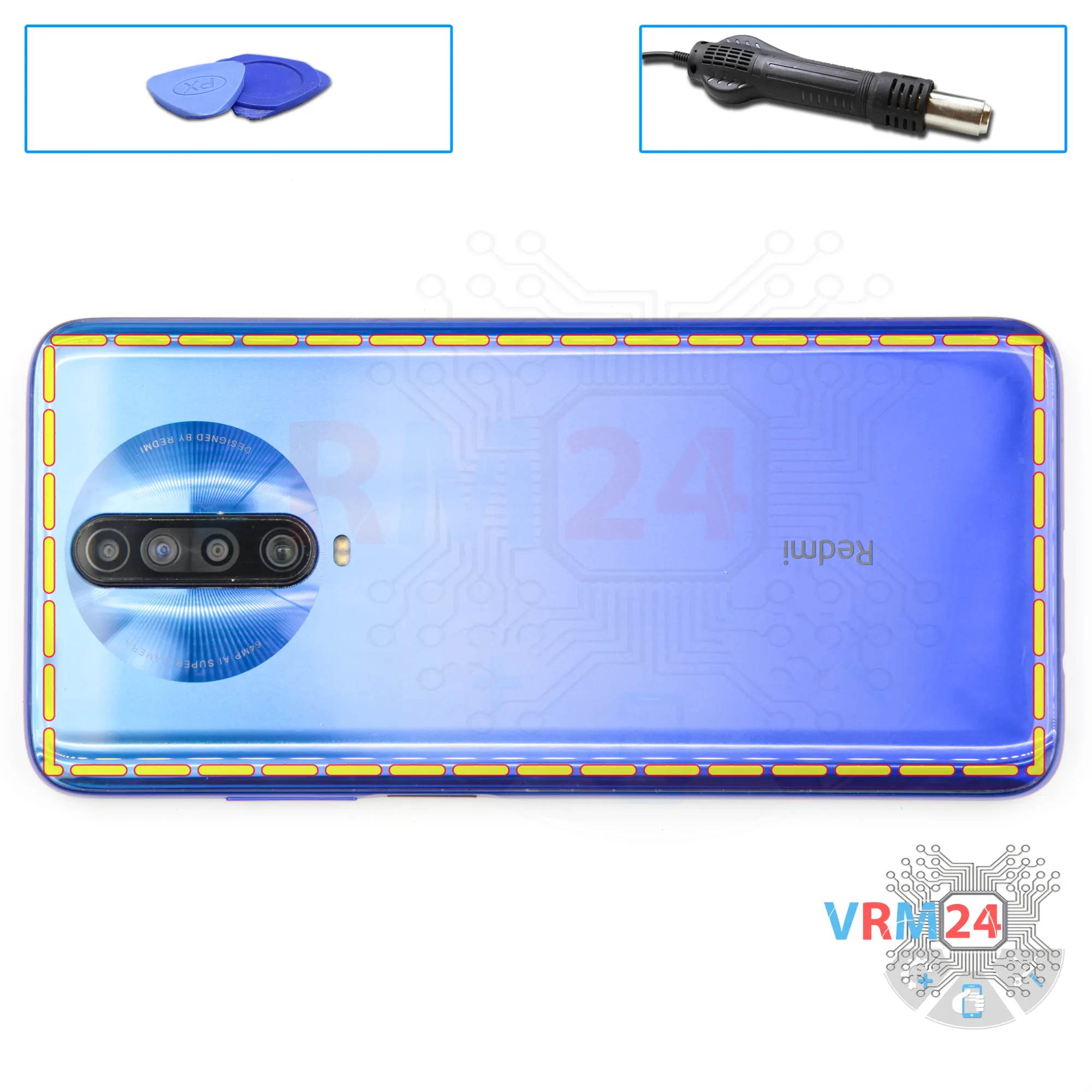
Open the back cover
After that we need to heat the surface of the back cover to a temperature of about 70 ° C or 160 ° F.
And after 5 to 7 minutes we can move on to disassembly.
To remove the back cover, we will use a plastic film, it is a protective film from a new display or a film from the stationery store.
We insert it into the gap between the middle cover and the back cover and run it along the edge cutting off the adhesive base.
Step 4.
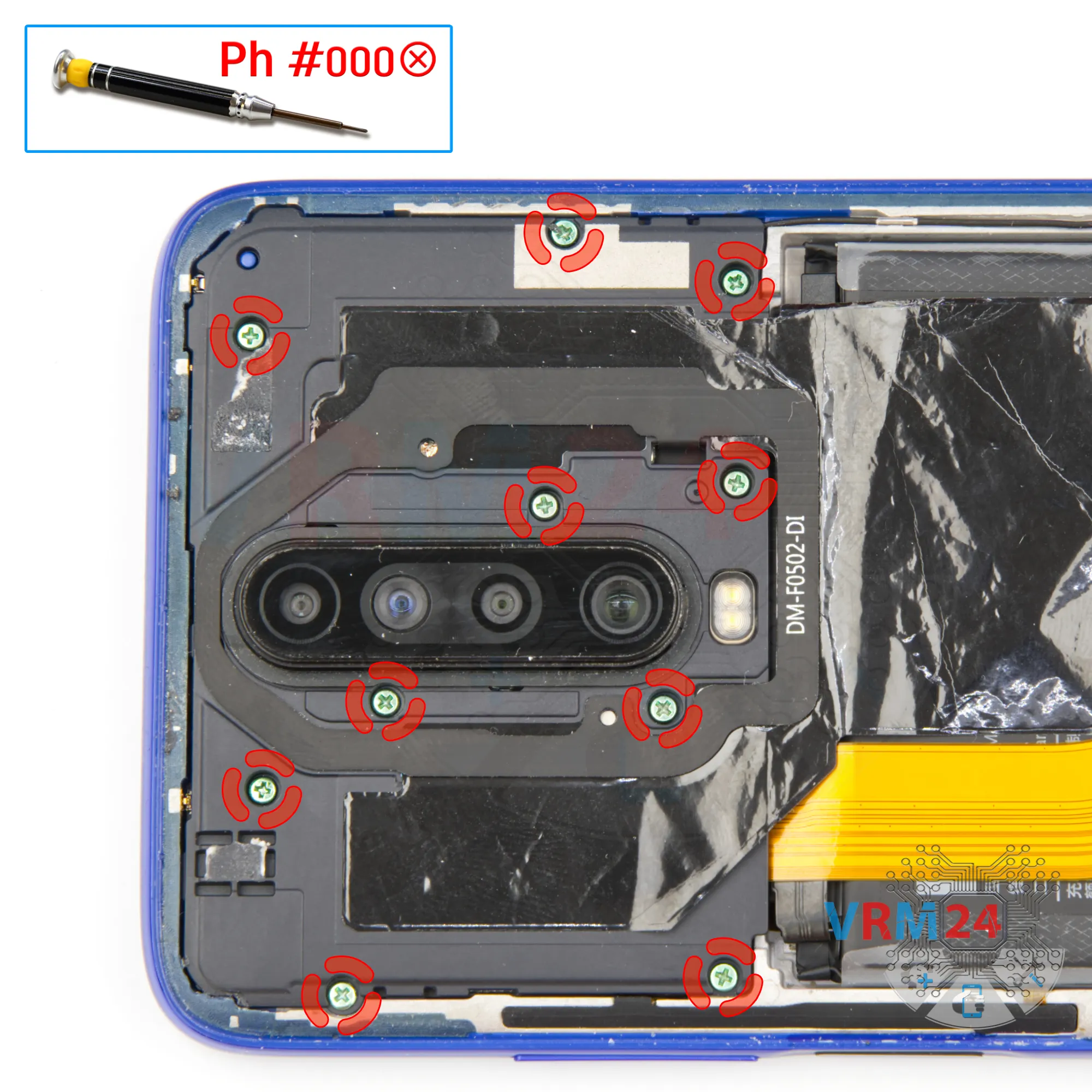
Unscrew the screws
Next, we move on to unscrewing the ten screws, we use a 1.5mm Phillips screwdriver or #000.
It looks like the screws are the same, but we still recommend placing them on a special surface in an easy-to-remember order just in case.
Step 5.
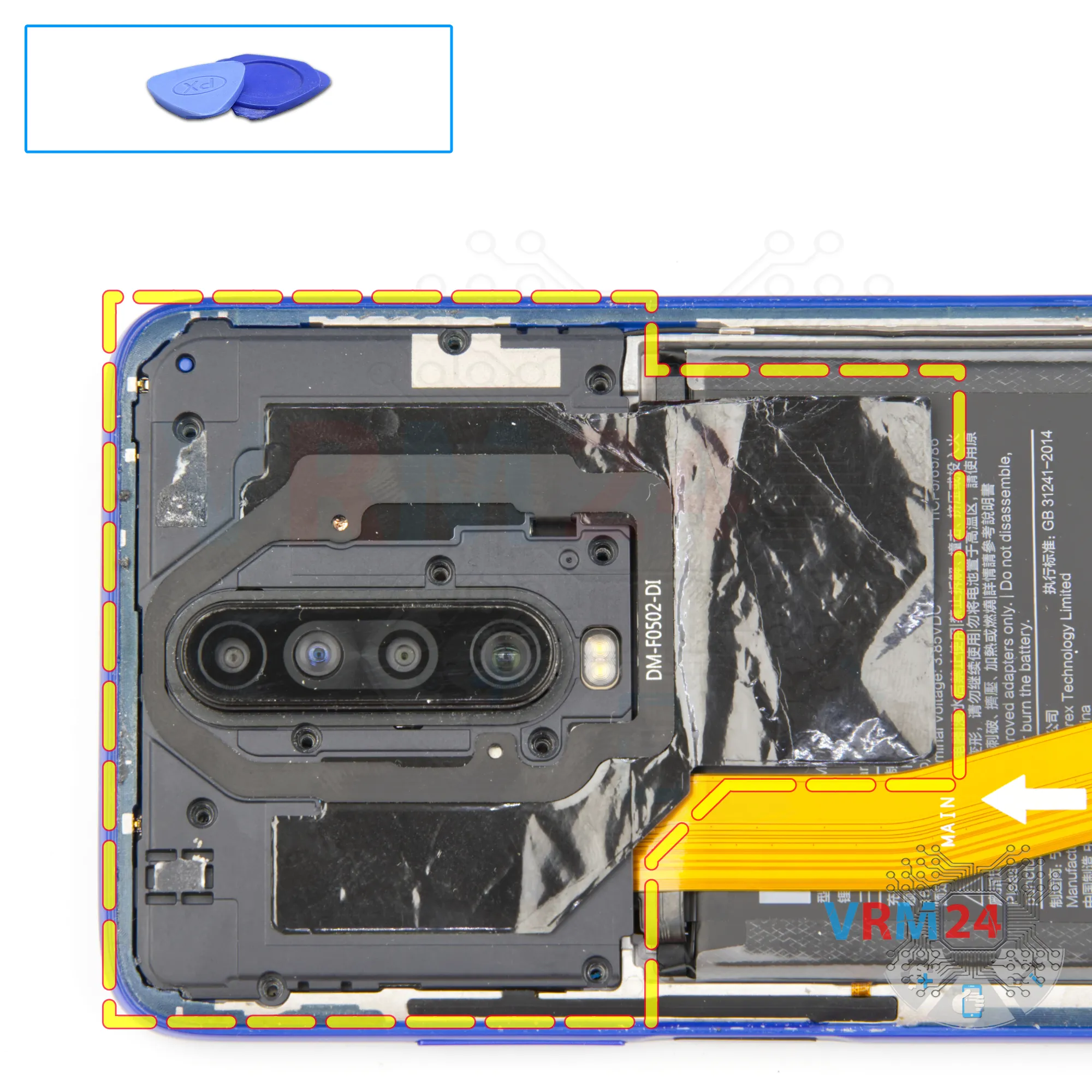
Open the cover
And using a non-metal tool, we detach the cover hiding the motherboard.
Step 6.
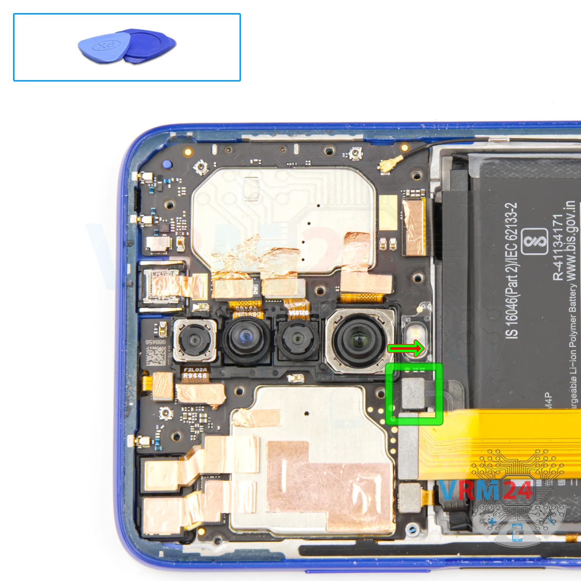
Disconnect the battery connector
Disconnect the battery connector as soon as you can. Use a non-metallic or plastic tool to avoid any damage.
ℹ️ The Xiaomi RedMi K30 M1912G7BC model has a battery BM4P with a capacity of 4500 mAh (also known as a rechargeable battery).
Step 7.
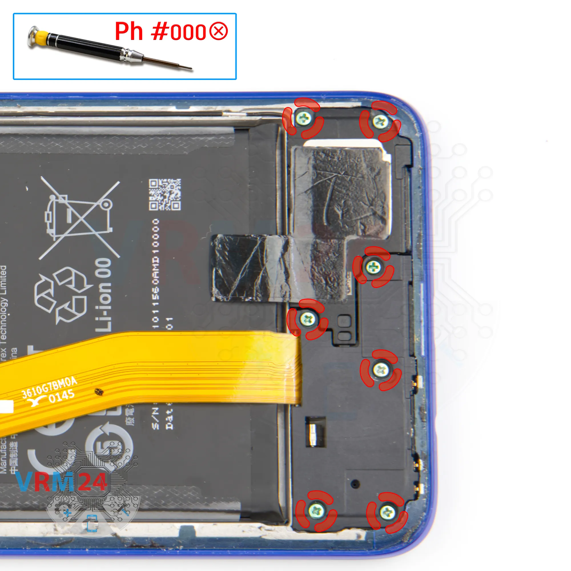
Unscrew the screws
And we move on to unscrewing the seven screws at the bottom.
The screwdriver is the same 1.5 mm Phillips screwdriver.
It looks like the screws are also the same, but we would still recommend placing them on a special surface in an easy to remember order for reassembly.
If a screw gets stuck, we can use tweezers to remove it.
Step 8.
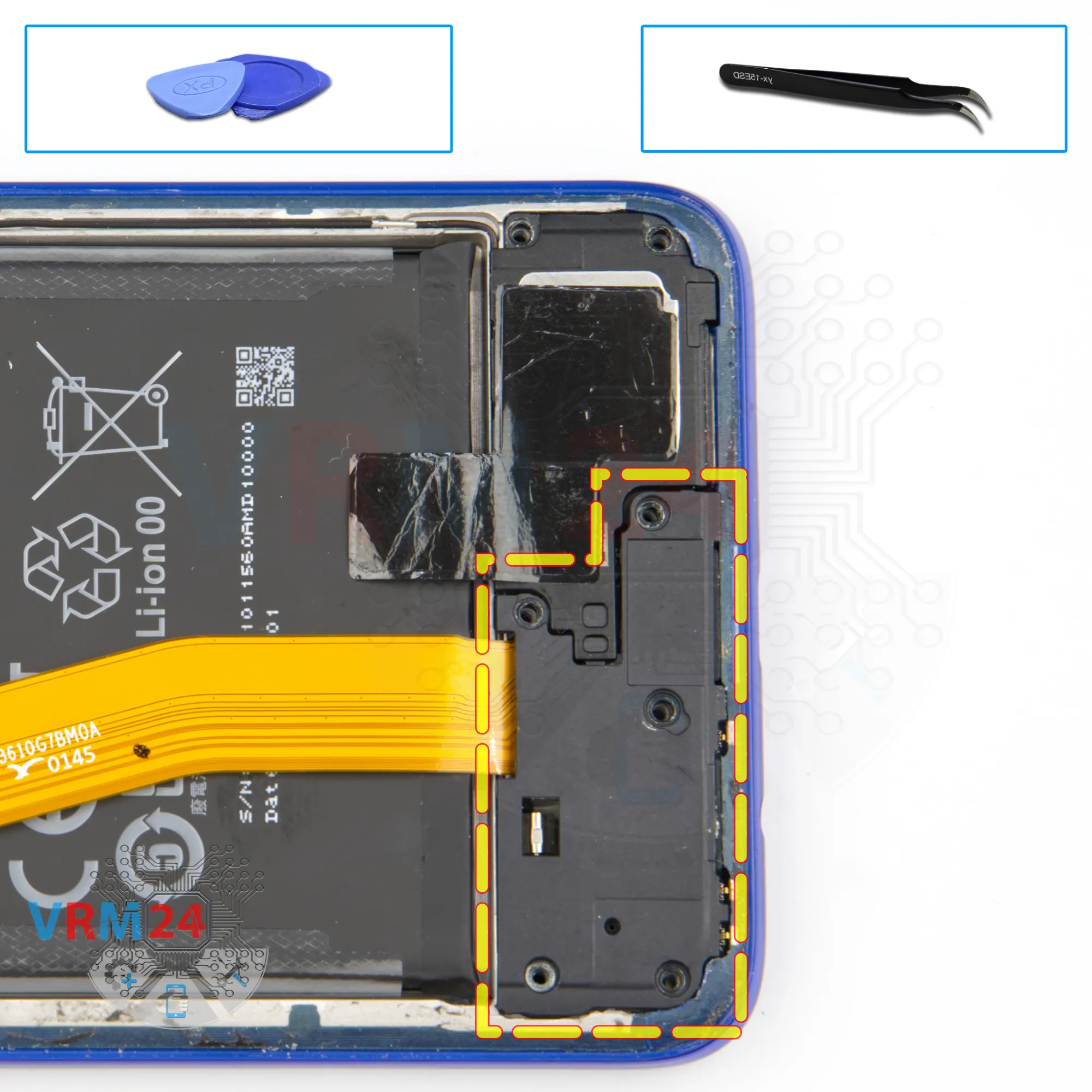
Open the cover
We can carefully detach the cover hiding the sub-board.
Step 9.
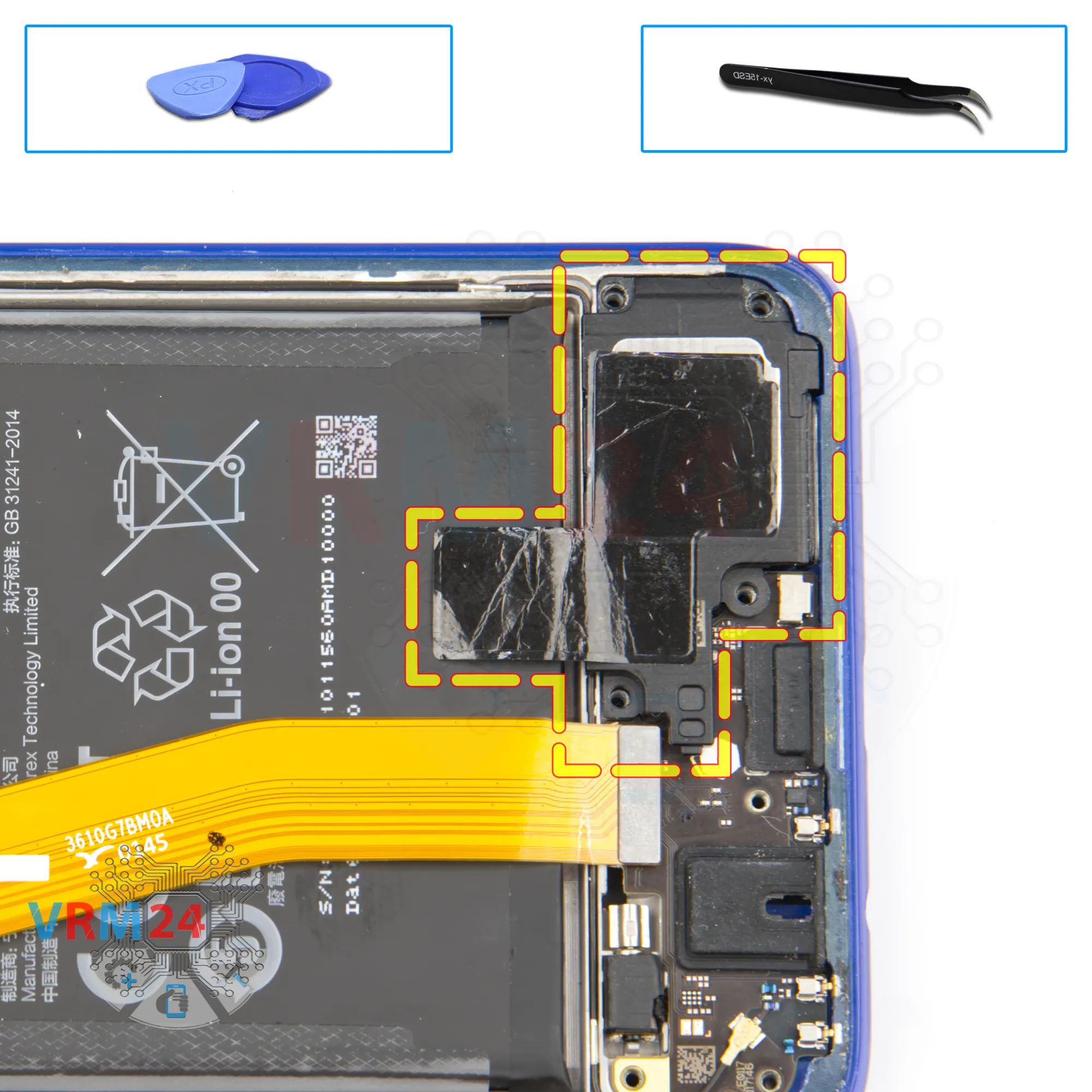
Remove the loudspeaker
We also detach the loudspeaker, gently hook it by the edge, lift it up and remove it.
Step 10.
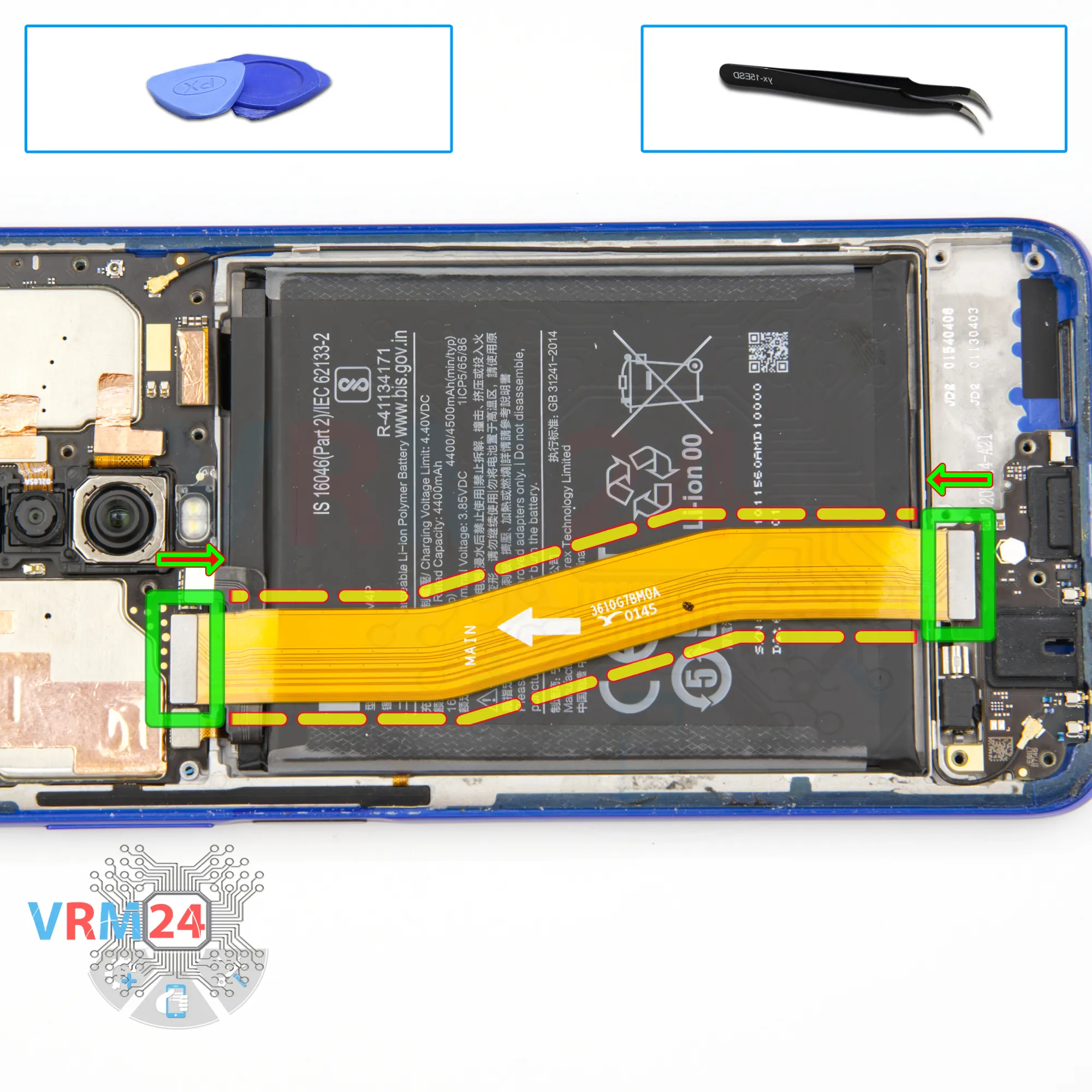
Remove the interconnect cable
Then we disconnect the connectors of the inter-board cable and put it aside.
The direction to the motherboard is indicated on the inter-board cable.
Step 11.
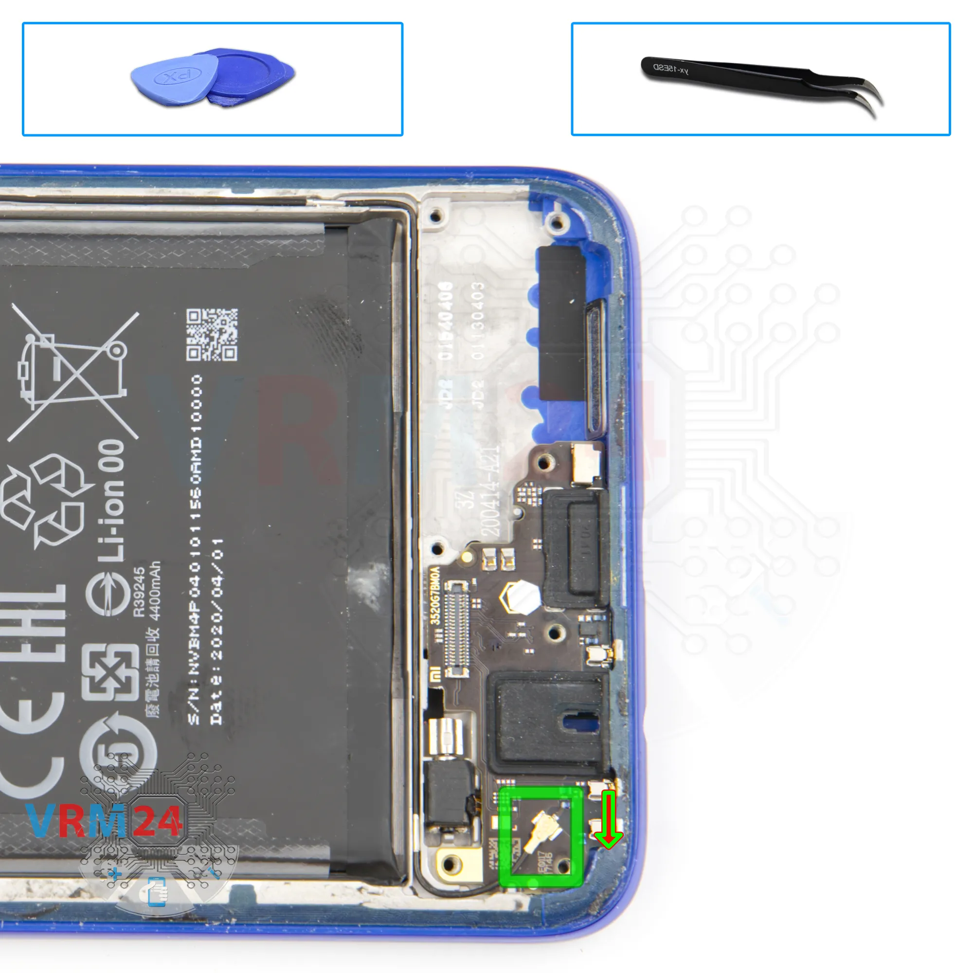
Disconnect the connector
We disconnect the coaxial cable connector and turn the cable aside so that it does not interfere with us.
Step 12.
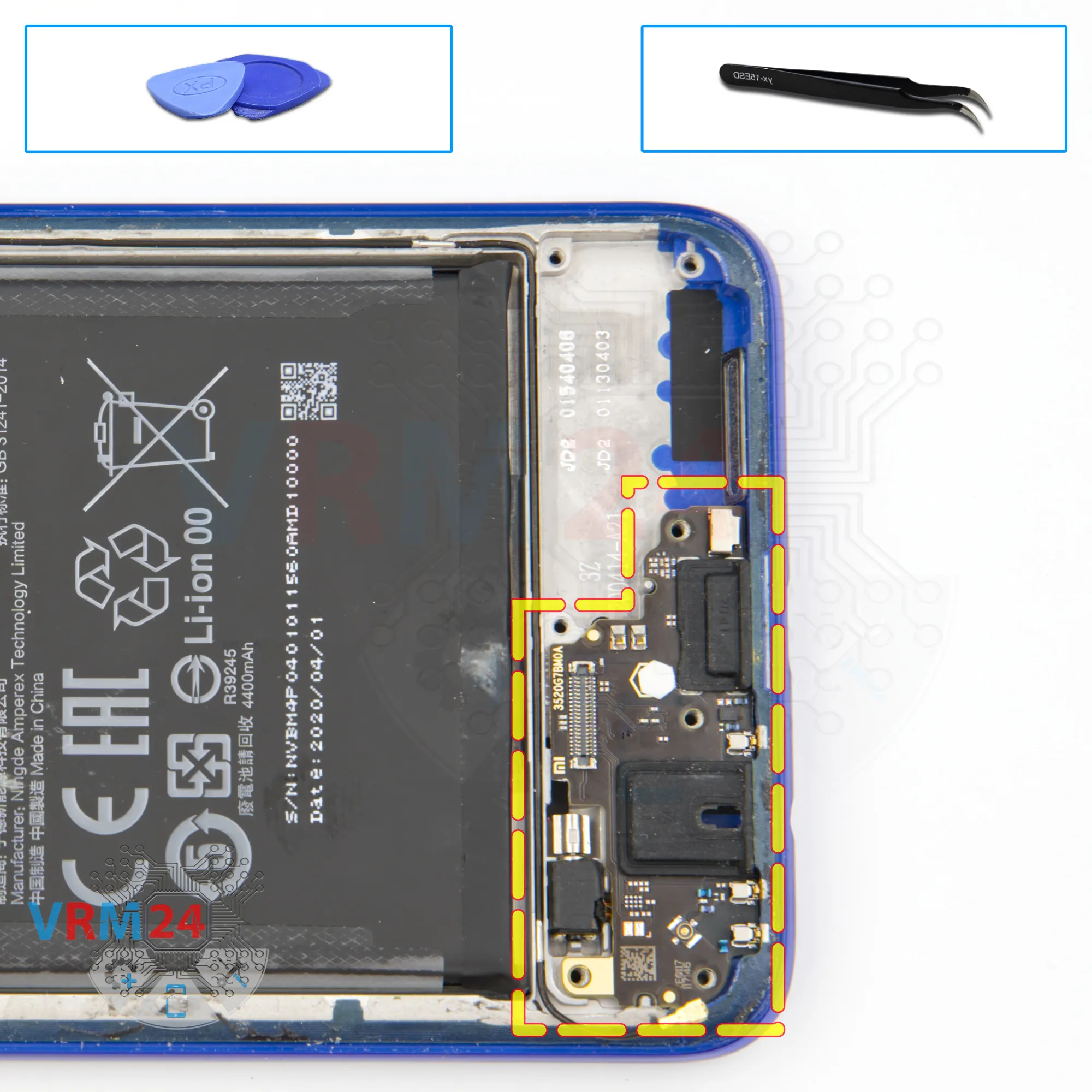
Remove the sub-board
We move on to detaching the sub-board.
We find the right and convenient place for us to hook the sub-board.
The sub-board is recessed into the display frame and is also held on clips or hooks. So it is really important to find the right place where we will lift it to avoid damaging anything.
On the sub-board we have the headset jack port, charging port, microphone and other elements on the inside.
Step 13.
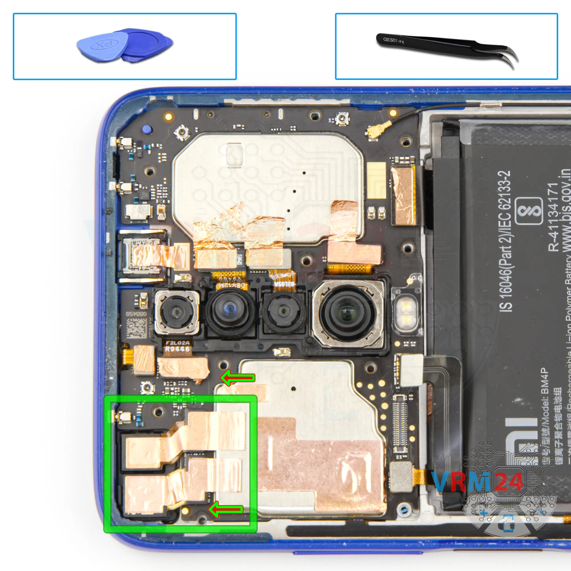
Remove the cameras
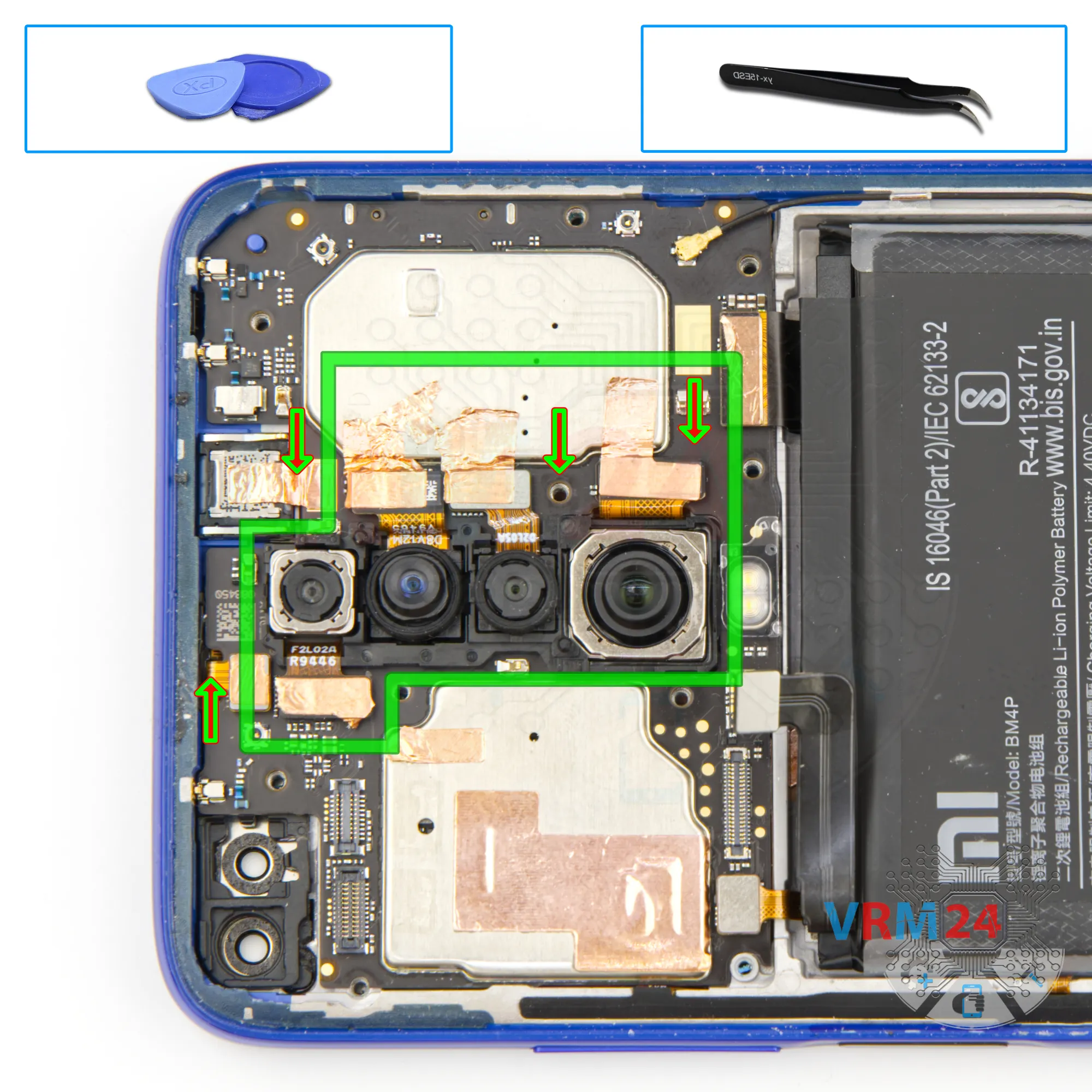
We move on to detaching the front cameras.
The cameras are glued to the shields on the motherboard with a copper heat-dissipating foil.
Step 14.
Remove the cameras
And we can detach the rear cameras, where we also try to keep the heat dissipation foil, because it dissipates heat from the cameras and at the same time not to damage the camera cables when detaching them.
Step 15.
Disconnect the connectors
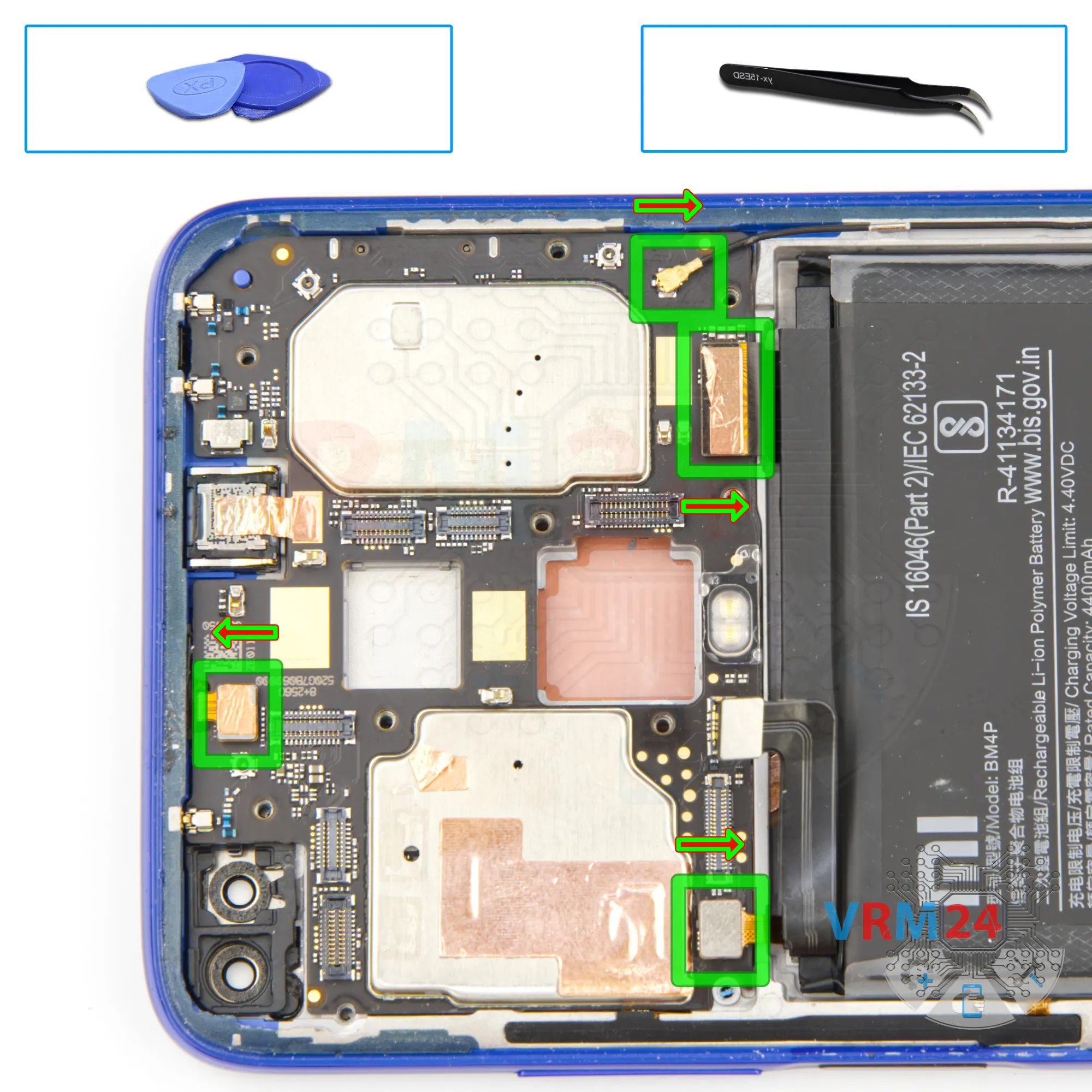
Let's move on to disconnecting the connectors.
We disconnect the display connector, coaxial cable connector, connector to the fingerprint sensor, and the connector to the sensors.
Step 16.
Remove the motherboard
And we can detach the circuit board.
We gently hook the edge, lift and remove the motherboard.
On the back side of the motherboard is located the card connector.
Step 17.
In the display frame remained
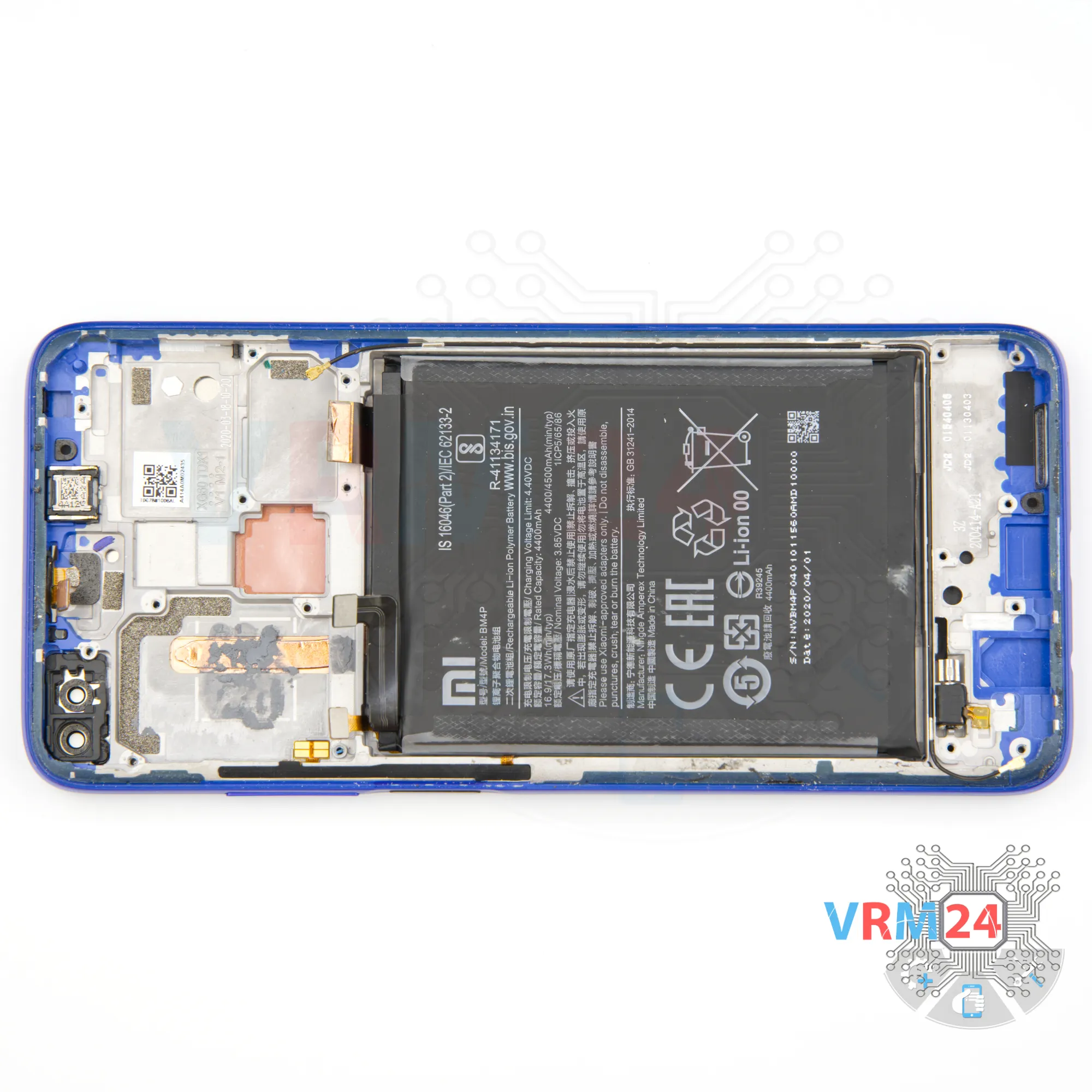
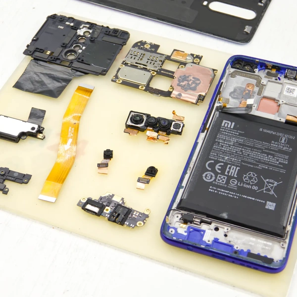
ℹ️ In the display frame remained: the earpiece speaker, battery, and vibration motor.

If you have a question, ask us, and we will try to answer in as much detail as possible. If this article was helpful for you, please rate it.

3999
Views
1
Likes
—
Share
0
Questions
Related Instructions
Related Reviews
Related Blog
Top instructions
Check our
Top Xiaomi instructions most liked by readers
New instructions
Check our
New Xiaomi brand instructions on vrm24.com